Shift from base-load to cycling duty requires mods to protect HRSG, reduce ‘standby’ costs
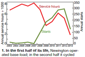 Essential Power Newington LLC, a 525-MW, 2 ×1 F-class dual-fuel combined cycle was designed to operate base-load—and did for about the first six years of its existence following commercial start in 2002. The plant averaged approximately 7500 hr/yr and 13 starts annually during that time.
A tolling agreement and cyclic operation began in June 2008, when Newington was acquired by Essential Power LLC. For the next five years, the facility averaged about 4800 service hours and 200 starts annually (Fig 1). However, hours/starts declined dramatically in 2013 to 1800/125. Among the reasons: The tolling agreement ended in June 2013 and gas supply in the Northeast became challenging.
Nitrogen mitigates HRSG corrosion, inerts gas lines during maintenance
Best of the Best Award
Challenge. During the shoulder months, Newington now can be offline for several days in a row, allowing the heat-recovery steam generators (HRSGs) to depressurize and permit the entry of air into the units.
Problems associated with improper layup include general corrosion, which contributes to elevated iron levels in boiler water, and pitting corrosion conducive to the cracking of pressure parts and waterside leaks. Improper layup also can force operators to extend startups to satisfy chemistry specifications.
For a few years the site relied on tube trailers for bulk nitrogen supply to the HRSGs, but that became costly as demurrage charges compounded and the uncertainty of needing a trailer became relevant.
In addition to HRSG wet-layup protection, there were many occasions where pipe purging of the fuel headers was necessary for routine and corrective maintenance. Previously, several 230-liter liquid-nitrogen dewars were used for this purpose. But they proved problematic because of product off-gassing, limited capacity, and difficulties associated with maneuvering the dewars into positions required for pipe inerting.
 Solution. In 2013, a nitrogen generator using state-of-the-art dual-bed pressure swing adsorption (PSA) technology was installed. The adsorption bed converts compressed air, readily available from plant supply, into a concentrated nitrogen output stream. Proper use of the integrated PLC-based control system assures the plant of nitrogen having a purity of 95.00% to 99.95%; the purity setting depends on the purge requirement.
The stationary generator provides a nitrogen blanket capable of preventing oxygen ingress and for improving the overall cycle chemistry of the plant’s two HRSGs. EPRI recommends a minimum of 99.6% nitrogen purity for wet layup of an HRSG. This easily accomplished by the system installed at the flow rate required.
During periods of fuel-pipe inerting, the generator can easily be set to purge any pipe in the plant, eliminating the need for several liquid nitrogen dewars. A quick connection to the nitrogen-generator outlet with a standard hose is used to reach any fuel-pipe tap necessary to inert the entire system prior to maintenance.
Results. The nitrogen generator has improved overall cycle chemistry by reducing iron deposition in the HRSG caused by surface corrosion. Plus, startup chemistry specifications are achieved much faster following a boiler layup with a nitrogen cap than without. Other benefits achieved include the following:
- Reduced nitrogen commodity costs with onsite production.
- No demurrage charges are incurred for rented bulk-nitrogen trailers or cylinders.
- No rental charges are incurred for liquid nitrogen dewars formerly used in pipe-inerting activities.
- The potential for employee injuries associated with handling cylinders and dewars has been eliminated.
Project participants:
Joshua Leighton, operations manager
Ted Karabinas, maintenance technician
Mod to auxiliary cooling system reduces station back-feed
Best of the Best Award
Challenge. With the change in Newington’s operating profile, a challenge surfaced with regard to adequate cooling of essential services with minimum electrical back-feed charges. The plant was constructed with a 10-cell induced-draft saltwater cooling tower. Cooling water (CW) for steam condensing and other plant uses is circulated by two 50% centrifugal pumps, each driven by a 2450-hp (4160 V) motor.
The plant also was equipped with a closed-loop cooling water (CCW) system to remove sensible heat from essential systems—including the steam- and gas-turbine lube-oil systems and generator hydrogen coolers. CCW, a blend of demineralized water and polypropylene glycol, is circulated by a 500-hp centrifugal pump. A full-size backup pump is in reserve.
Plant designers did not provide for auxiliary off-line cooling with either the CW or CCW systems. Thus, during periods where the plant is not dispatched, or during maintenance outages, the only method of cooling available is continued use of the main CW and CCW pumps (total of 2950 hp)—far and above that required for removing sensible heat generated by lube-oil systems under off-line conditions. Use of these systems when the plant isn’t dispatched results in excessive electrical back-feed charges from the local utility.
Solution. Newington personnel approached the retrofit of auxiliary cooling capability in two phases. The first phase involved installation of an auxiliary CCW pump. Calculations revealed that the amount of sensible heat to be removed from the CCW system when the plant was offline was only about 500,000 Btu/hr. As a frame of reference, the two CCW plate-and-frame heat exchangers each are sized for 100 times this amount of heat-transfer duty.
Even though the heat-removal requirements were quite small, plant staff recognized the importance of ensuring that CCW flowed where required and in sufficient quantity to remove heat from the system (Fig 2). During design of the auxiliary system, plant personnel identified an unused 10-hp demineralized-water transfer pump.
After reviewing its capability and construction, they decided to design the piping system to accommodate the surplus pump, rated 700 gpm at 40 ft TDH, for CCW duty. However, during warm ambient conditions, the auxiliary CCW circulation was insufficient to cool the turbine lube-oil systems—this despite uninsulated CCW piping.

The second phase of the auxiliary cooling project involved evaluation of other possible ways to provide the additional cooling required. First thought was to install a fin/fan cooler for the auxiliary CCW system, but this idea was abandoned because of high construction costs and the large footprint needed for the cooler. Next, plant personnel evaluated installation of an auxiliary CW pump.
Here’s what they learned: The CCW plate-and-frame heat exchangers were located so close to the steam turbine’s condenser that the overall head requirement for an auxiliary CW pump would be less than 10 ft TDH. A proof-of-concept test conducted during a plant outage confirmed that a low-head auxiliary pump would provide sufficient cooling flow to the CCW heat exchangers to eliminate the issue (Fig 3).
Based upon this successful test, plant personnel designed and installed an auxiliary CW system—including a self-priming fiberglass-reinforced-plastic (FRP) centrifugal pump capable of 1050 gpm at 20 ft TDH. The new pump is driven by a 20-hp (480 V) motor.
Results. Installation of the two auxiliary pumps produced immediate benefits for the facility. The original estimate of payback period for the auxiliary CCW pump was approximately three years. But because of the low plant capacity factor in 2013, the actual payback was less than one year.
The auxiliary CW pump was not installed until 4Q/2013 so the actual payback period still is not known. However, the replacement of approximately 3000 hp of pumping power with 30 hp is dramatic.
In addition, there are several additional economic benefits to having the new auxiliary pumps beyond electrical back-feed charges. These include:
- Eliminates the rental of a diesel-powered pump when maintenance is required for one of the two 100% CCW pumps.
- Eliminates rental of temporary CW pump and hose during planned maintenance outages. This has the added benefit of eliminating potential spills from the temporary system, as well as eliminating potential trip hazards by removal of temporary hoses.
- During periods when the plant is not dispatched, the new auxiliary CW pump can be used to circulate and blow down cooling-tower water while maintaining compliance with the plant’s NPDES permit minimum-flow requirement.
Project participants:
Eric Pigman, plant engineer
Ted Karabinas, maintenance technician
Scott Courtois, instrumentation technician
16-kV switchgear IR scanning windows
Best Practices Award
Challenge. When the plant was constructed, the installed Siemens 4.16-kV switchgear had no means of performing infrared scans for the electrical connections on the bus to identify hotspots or electrical issues.
During subsequent budget planning processes, this identified deficiency was always put to a lower priority since much larger and higher impact projects were in need of completion. For several outages, plant personnel attempted to get this work completed but the switchgear was never completely isolated in lieu of other workscopes.
Due to the critical nature of the 4.16-kV switchgear feeding the 4.16-kV motor control centers (Fig 4) and 4.16-kV-480-V station service transformers, this project was given a higher priority in 2013 and the switchgear was isolated.

Solution. Plant personnel purchased IR scanning windows through a local IRISS Inc rep and had it install them during a plant outage in October 2013. The two products chosen for Newington were the IRISS Platinum Series CAP-CT-12 rectangular and IRISS Platinum Series VPT-100 round windows. The rectangular windows (Fig 5) were chosen because they allow multiple processes to be conducted as part of the site PdM program—such as visual, traditional infrared (IR), and the added functionality of ultraviolet (UV) that some other windows do not allow.
Configuration of the switchgear internals required installation of some round windows to assure full visibility. While windows were being installed and access covers were removed, site performed a full cleaning and connection inspection of the 4.16-kV switchgear; no issues were identified.
Results. Site has a contract with a local ASNT certified IR/UV technician to perform semi-annual thermography of the entire site electrical layout as well as HRSG and steam-turbine valves, GT compressor bleed valves, etc. These windows have been added to that list. The first scan using these windows will serve as a baseline for future comparison.
Project participant:
Chad Harrison, maintenance manager
CEMS shelter oxygen analyzer keeps operators safe
Challenge. The plant was constructed with two independent continuous emissions monitoring systems (CEMS). They are located inside separate shelters near the base of the stack. The CEMS are considered critical equipment and continuously sample stack gas to ensure compliance with the various emission limits listed in the facility’s Title V Air Permit.
The CEMS systems are required to be calibrated each operating day using specific protocol gases, some of which can cause an atmospheric 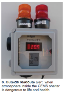 hazard if released inside tight quarters. The protocol gases used for CEMS calibration include NH3, CO, O2, and N2 and are stored outside the shelter. However, there are several potential failure points inside each CEMS shelter which may cause protocol gases to be released inside the shelter.
In addition, the plant installed its nitrogen generator for HRSG wet layup and pipe inerting inside one of the shelters. A leaking connection from either the nitrogen generator or CEMS could result in an oxygen-deficient or oxygen-enriched atmosphere.
Solution. The plant worked with a local vendor to identify an industrial- grade instrument capable of continuously monitoring the O2 concentration within each CEMS shelter. The analyzer displays the oxygen reading to a local readout just outside the shelter door, allowing plant personnel to verify oxygen concentration prior to entering the shelter (Fig 6). The analyzer is also equipped with an audible alarm and flashing beacons for both a low oxygen content and high oxygen content.
Results. While the CEMS shelters are not continuously occupied, the shelters are entered during operator rounds, routine PM checks, and for troubleshooting. The new analyzers are a good continuous improvement, ensuring that plant personnel do not enter or work in an atmosphere dangerous to life and health.
Project participants:
Joshua Leighton, operations manager
Patrick Torra, I&C technician
David Cribbie, EH&S manager