
CONTENTS
Industry Issues: prognostics
High-Energy Piping concerns
Cold-weather operational impacts
GE F-class engines
GE E- and Legacy-class GTs
P&W Roundtable
7F compressor inspections
CTOTF’s 39th year of service to the electric power industry concludes with the organization’s 2014 Fall Conference & Trade Show, September 7-11, at the Rancho Bernardo Inn, San Diego. The program is fluid, with updates posted at www.ctotf.org as they are received. You can register for the meeting and reserve a room at the conference hotel on the same web page. As this issue went to press, early in the program development process, meeting highlights included the following:
- Full-day sessions dedicated to GE F-class gas turbines (GTs), Siemens F- and G-class engines, Aero GTs (GE, P&W, and Solar), and Generators/HV Electrical/I&C.
- Half-day sessions addressing Industry Issues, O&M and Business Practices, Regulatory & Compliance, GE E- and EA-class engines, Combined Cycles, Siemens V- and H-class machines, and Legacy GTs.
- Half of the Combined Cycle Roundtable (“session” in CTOTF lingo) will be dedicated to fleet issues with GE D-11 steam turbines. Speakers from the OEM and EthosEnergy will offer their thoughts on possible resolutions prior to an open discussion session. The second half of the roundtable will focus on cold-weather preparations and best practices suggested by a user from Alaska, and a supplier of electric heat-trace systems.
- The Wednesday morning segment of the GE F-class program features presentations by, and discussion with, the OEM’s engineers. Three presentations are scheduled for the afternoon: A user’s experience upgrading a 7FB.01 to .04, Allied Power Group’s Aaron Frost on poor repair practices to watch for, and Mistras Group on acoustic monitoring for compressor blade cracking.
CTOTF Fall 2013
Last fall’s conference (Coeur d’Alene, Idaho) opened with several industry leaders sharing their expertise on new tools for plant-performance improvement during the Industry Issues and O&M and Business Practices Roundtables. There were quality presentations on fleet-wide monitoring and diagnostic (M&D) centers, new automation and knowledge management techniques, and a relatively new field—lately called prognostics.
Many large fleet owner/operators have installed remote M&D centers, also called performance optimization or plant operations centers. NV Energy is one of the latest to commission one. A presentation by the utility’s Brian Paetzold and Andy Gaither focused on pattern-recognition technology, one form of prognostics.
Tom Burger, plant manager of Entegra Power Group’s Union Power Station in El Dorado, Ark, narrowed in on a successful application of Emerson Process Management’s AMS Suite to reduce maintenance and expenses associated with I&C. Entegra turned a reactive valve maintenance program into a predictive one.
Robert Yeager, president of Emerson’s Power & Water Solutions business unit, focused his remarks on prognostic control, how sophisticated data analytics and big-data algorithms can be combined with super-fast simulation to inform real-time decisions. In this way, monitored variables are tracked and compared using multi-variate techniques and the control system is run, in effect, in fast forward to predict how the plant will respond. The latter is performed using a virtual model of the control system that runs in parallel with the real plant control system. Much of this capability can now be embedded in the controllers, avoiding separate systems pulling from an independent data historian.
Chad Stoecker, GE Intelligent Platforms (formerly SmartSignal Corp), tackled the industrial Internet. Echoing GE’s last big marketing push, Ecomagination, Stoecker defined the forces driving the industrial Internet as pervasive connectivity, intelligent machines, big (industrial) data, and advanced analytics.
In the afternoon session, Stoecker drilled down to Proficy, GE’s predictive analytics solution, as applied for gas-turbine-based systems. He offered many examples of how issues were detected before they became big problems or failures. These included: nozzle issues after hot-gas-path overhaul, broken variable bleed valve ahead of a unit trip, faulty burner tips, and turbine blade rub. Stoecker pushed GE’s corporate Industrial Performance and Reliability Center as a key part of the company’s offering.
Jason Makansi, Pearl Street Inc, started off the morning session, after an introduction from Session Chair Ozzie Lomax, Ameren Missouri’s Manager of Gas Turbine and Renewable Generation, by revisiting some history in the development of prognostics for power stations. He defined prognostics as software, technologies, techniques, and algorithms which analyze real-time and historical data to make judgments about the future with respect to operations, maintenance, and asset/plant management. In a simpler vein, prognostics provide operator alerts well before the control system sounds an alarm. He also explained how prognostics are integrated into the balance of the “digital plant” complex.
One analogy is that diagnostics tell you when the machine has a life-threatening issue, prognostics can tell you how long the machine has to live—at least from a probabilistic risk perspective.
The panelists mentioned myriad challenges associated with successfully applying prognostics over the long haul, especially from the perspective of the plant staff. Cybersecurity clearly is a big challenge, but a discussion on that topic could have taken all the oxygen out of the room. All agreed that such technologies need a “champion” at the plant for a successful implementation.
Ray DeBerge, a member of CTOTF’s Executive Committee and Lomax’ lieutenant for technical services, kept the discussion grounded in practicalities by asking rhetorically, does the technology drive the “dumbing down” of operators? He also noted that M&D centers may not offer much value for GT peakers. Lomax grounded the discussion further, identifying a specific catastrophic failure of a torque converter, then asking the panelists, in effect, “what solutions do you guys have for me?”
A user in the audience, who claimed to be one of the first owner/operators to apply CycleWatch, a GE/Smart Signal product specifically developed for the variable, non-steady-state nature of startups and shutdowns, cautioned others to understand which indicators are really relevant and which are not. Another attendee asked how can you do a better job with knowledge engineering when you aren’t well-instrumented? One of the NV Energy speakers observed that, in their early experience, over half of the advisories from the center involve instrumentation.

Plant operations personnel expressed a healthy skepticism over prognostics. All of the presenters, in one way or another, addressed what perhaps is the greatest challenge: the disruption to traditional plant processes and organizations. Centralized M&D often is perceived, at least initially, by the plants as “big brother” and a nuisance because advisories generally are not well-vetted.
No one on the panel would argue that it is critical to pay as much, if not more, attention to communication within the organization as to the technology implementation. Yeager stressed at the top that “the human is an integral part of the control loop.” Even so, prognostic control can be run closed-loop, with the “system” simply alerting the human about what it is up to.
Makansi observed that prognostics advocates focus almost exclusively on the “catches,” alerts, and predictions which prevented failures. He suggested users measure and report non-catches as well, and develop metrics that capture value lost from poor predictions or poor communication relative to value gained from preventing failures and incidents.
Clearly, there is much value in these technologies. Entegra has cut in half the labor required for calibrations. All documentation for instrumentation is now managed with greater accuracy and consistency in the AMS digital system. In one instance, NV Energy received an alert that avoided close to $1-million in expenses associated with a potential attemperator failure (Fig 1). Whether they detect issues better or faster than properly trained and competent human operators remains a valid point of contention, but virtually everyone knows the real question is whether the new technologies can do as much, or more, for less money.
Tiger. One of the featured presentations at the Generators/HV Electrical/I&C Roundtable, “Techniques for Effective Monitoring and Diagnostics of Gas Turbines,” extended the diagnostics and predictive-analytics theme of the conference through the final day of the meeting. The presenter was Dr Charlie Nicol, diagnostic systems manager for Turbine Services Ltd, a wholly owned subsidiary of Chromalloy.
Nicol has been the chief architect for the Tiger turbine monitoring and diagnostic system since its birth more than 20 years ago. Background: Tiger began as a European funded project, involving a multinational consortium taking leading-edge research and applying it to the monitoring and diagnosis of GTs. The commercial product, developed by Intelligent Applications, was acquired by Sermatech and subsequently by Chromalloy.
Tiger is installed on 90 turbines today—including several models of gas-turbine frames and aeros, as well as steam turbines. The product generally has an excellent reputation among long-term users, but one has to wonder why there aren’t many more plants using this diagnostic system. Perhaps it was the prolonged period of development and too many participants in that process; it took 17 years to go from a prototype to 60 installations two years ago.
After listening to the presentations on the first day of the fall meeting, it may be that GE Intelligent Platforms (read SmartSignal) and others have passed Tiger by—at least in the US. Aggregating data from many like machines improves the predictive models and an aggressive OEM certainly has a leg up in this regard. Engines current Tiger users are operating include GE Frames 5 (two shaft), 6B, and 7EA; GE aeros LM2500 and LM6000; P&W FT4; 501F; GE steam turbine.
Nicol’s presentation began with the ABCs—the reasons for monitoring and diagnostics, the skill sets required by those interpreting and using the information collected from your engine, how an incident profile benefits the engine owner/operator (such as planning corrective action), etc. He then dissected the software and explained its structure and functionality, and how the company’s M&D center in Glasgow works.
Nicol noted that Tiger classifies diagnostics according to severity, turbine area, relevance to the main conclusion, and number of occurrences. It enables the user, he said, to easily replay the data, graph the information, access turbine manuals, link to user-specific notes, etc. Nicol then gave some examples of Tiger’s “finds,” such as sticking fuel and bleed valves, faulty controller cards, improperly operating speed ratio valve, faulty vibration sensor, etc. Digging into the details, he used bearings to illustrate how Tiger uses diagnostics (vibration data in this case) to detect bearing unbalance, misalignment, oil whip, oil whirl, rubs, and/or blade damage.
There were a few dozen more slides illustrating information displays in chart and table form, how to track startups and shutdowns and use aggregated data to guide future starts and stops, how different variables are displayed on-screen, etc. Find Nichol’s presentation, and others made at CTOTF meetings over the last 10 years, in the organization’s keyword-searchable library at forums.ctotf.org. The archive, which now contains more than 500 presentations on GT technology, operation, and maintenance, is available only to users. Sign up today if you are not already registered—no charge. Instructions are in the sidebar.
HEP concerns
The attemperator photo (Fig 1) was the perfect introduction to the Combined Cycle Roundtable, where this equipment is discussed. Ed Sundheim, CTOTF vice chair for program development and director of engineering for Essential Power LLC, made a short presentation summarizing common failures in “boom-era” high-energy piping (HEP) systems. It provided particularly valuable perspective for engineers new to the industry and those whose professional positions focus on the Brayton side of combined cycles.
It was not Sundheim’s intent to provide details, but rather to identify potential problem areas that bear watching. Background and current information on each of these topics can be accessed by using the search function in the top right corner of the CCJ ONline home page at www.ccj-online.com. He focused on three areas:
Attemperators, noting poor design, improper location in piping systems, leaking spray valves, thermal fatigue damage, etc.
P91 and material issues in pipe runs, valves, fittings, welds, etc, primarily related to deficient quality control during manufacture and installation.
Liberation of stellite hard-facing in main and reheat stop and non-return valves, and steam turbine stop and control valves as well.
Sundheim spoke to what he called a “daisy-chain” of HEP failures. His professional opinion, based on a 50-year association with powerplant equipment, is that many problems owner/operators face today can be traced to poor initial design, fabrication, and construction. He believes that some designers did not/may still not adequately understand high cycling stresses or the cures. Also, that some contractors did not/may still not fully appreciate the critical nature of P91 welding and heat-treatment requirements and the need for tight quality control. Finally, he questioned the origin of some Code documentation owner/operators have been given.
High cycling and part-load operation of combined-cycle units designed for base-load service have contributed to the issues noted. Sundheim mentioned the overuse of attemperators and the resulting failures caused by quenching, as well as nightly shutdowns that are conducive to condensation and slugs of water in steam systems and consequent quenching damage.
Stellite liberation is an issue Sundheim is following closely and he urged others to do the same. He said it has become a significant industry-wide problem with more than 50 cases already reported. Damage has been associated with the products of most all manufacturers of P91 stop and non-return valves for HEP systems; plus, the major steam-turbine OEMs have acknowledged problems with their valves. At the present time, Sundheim said, there’s no foolproof method for attaching stellite to P91—at least based on his research.
EPRI is leading a study on the problem but no concrete findings have been announced yet to the editors’ knowledge. In the meantime, at least one plant owner believes it’s time to consider alternatives to stellite hardfacing. It is taking a proactive approach in buying replacement valves from a supplier with little experience in the manufacture of steam valves for F-class combined cycles but with positive experience in the use of chromium-carbide-based proprietary material on wear faces. Stay tuned.
P91 valves. Next, Sundheim alerted attendees to a new problem associated with P91 steam valves: the incompatibility of Type 316 stainless steel seat rings with P91 bodies because of differential expansion issues. In wrapping up, he suggested that users consider starting an HEP health monitoring program, or upgrading the one they have, consistent with new industry findings. Here are his recommendations:
- Inspect all P91 welds and heat-affected zones for proper hardness.
- Establish a Code compliance program.
- Research your HEP Code documents.
- Establish strict standards for HEP repairs and monitor/inspect work carefully.
- Vet all HEP suppliers and services providers.
- Avoid field welding of P91 where possible.
Other recommendations:
- Regarding steam turbines, follow prescribed OEM guideline documents—such as GE’s Technical Information Letter 1629-R1, “Combined Stop and Control Valve Seat Stellite Liberation.”
- Monitor and inspect attemperators regularly.
- Monitor main steam and reheater drains for proper operation.
HRSG drains. Sundheim paused here to stress the importance of proper operation and maintenance of drain systems for preventing the formation of condensate and subsequent chill-shocking of valves and attemperators. In recent conversations with other combined-cycle operators he reported hearing this common theme: HRSG drain systems are maintenance hogs because of their (1) location at the bottom of the boiler where they are prone to attack by gas-path condensation /corrosion, (2) parsimonious allowance for thermal expansion, and (3) cycling beyond design assumptions.
“At our Newington plant,” he added, “we have gone through an extensive refit of the HRSG drain systems” and have done the following:
- Added insulation to prevent corrosion to the extent possible.
- Provided for thermal expansion.
- Installed redundant stop valves so that one valve throttles and the other only sees full-open/closed service. “By eliminating the fears of operators that they might cause a valve or line failure, plant personnel are now less reluctant to operate the drains and we have much better control over condensation/slugs,” Sundheim said.
- Planned to add drain pots in each line when the maintenance budget permits. The drain pots will be equipped with thermocouples so the control-room operator will know when the line is blowing liquid or wasting steam.
Cold-weather operational impacts
Personnel at plants in cold climes generally are adept at dealing with winter weather events and prepare accordingly. However, facilities to the south often are caught “napping.” The consequences can be severe. During the Regulatory and Compliance Roundtable, a user reported on lessons learned from cold-weather incidents. The information was compiled by NERC. The following case histories were excerpted from that presentation.
Case History 1. During a severe winter weather event, human performance errors caused generating units to trip, requiring rolling load sheds.
Lessons learned: To maximize human performance during adverse conditions consider doing the following:
- Train personnel on the plant’s plans for freeze protection and emergency cold weather operation to provide them better insight into the challenges presented by winter events and how to deal with them.
- Develop and practice procedures to manually receive critical operating data in case instruments and transmitters malfunction or freeze.
- Assign to the plant for the duration of extreme weather events additional personnel who are trained to perform critical jobs.
Case History 2. Very low temperatures forced a plant offline. The balancing authority and reliability coordinator had not been informed that the plant was not designed to operate during such extreme conditions.
Lessons learned. The generator owner/operator is responsible for the following:
- Know the ambient-temperature limitations of the plant and inform grid management of the low-temperature limit.
- Establish procedures that stress identification of possible freeze areas after maintenance or design changes and upgrade protection as necessary.
- Enable operation at low ambient temperatures by identifying areas of the plant susceptible to freezing and adding insulation, heat tracing, and wind breaks to maintain water temperature at 40F or above.
- Document and institutionalize knowledge and experiences from previous severe winter weather events and apply this learning to winterization procedures.
Case History 3. During an extreme winter weather event, a five-unit combined cycle had engines fail to start, or trip, numerous times because of frozen instrument transmitters and sensing lines. The loss of generation forced the balancing authority and reliability coordinator to shed load.
Lessons learned included the following:
- Appropriate consideration should be given to the potential effects of wind in removing heat from equipment.
- Bypass the cooling water system, if possible, during very cold weather to prevent freeze-up.
- Purge transmitter sensing lines inside the GT package prior to winter weather events to prevent the build-up of condensation which could then freeze.
- Identify unit-specific critical freeze-protection areas and the work required to decrease the likelihood of long-duration freeze impacts.
- Develop emergency operating procedures to allow unit operation in freezing weather when critical instrumentation is lost.
- Where feasible, monitor heat-tracing circuits to verify circuit integrity. Also, check amperage and voltage periodically to assure that circuits are operating at their design output.
- Heat tracing doesn’t last forever; develop a replacement schedule in accordance with the manufacturer’s recommendations.
GE F-class engines
The GE F-Class Roundtable was intense, running virtually non-stop from 8 am to 5 pm. Session Chair Pierre Boehler, a senior engineer for NRG Energy Inc, and Vice Chair Mike Hartsig, plant manager for Star West Generation LLC’s 2 × 1 Griffith Energy, organized 11 prepared presentations and several open discussion sessions that more than filled the day.
The morning was dedicated to presentations by the OEM and open discussion between owner/operators and the GE team. Key presentation topics were an update on the compressor section, 7F design evolution and hot-section changes, new naming convention, compressor-blade monitoring system, hot-section hardware, and the OEM’s designs to address new market requirements—such as fast start/fast ramp capability.
An open discussion on getting more life from existing hardware was good segue for repair expert Hans van Esch’s (TEServices™, Houston) afternoon tutorial, “Extending 7FA Parts Life Beyond the OEM’s Recommendation.”
Several of the GE presentations were valuable for their ability to put everyone in the room on the same page, no matter what their level of experience. For example, the compressor presentation offered details on the company’s enhanced packages for both flared and unflared units. Unless this information is available on the screen, users can get lost in the storm of nomenclature and tune out.
Example: One slide describing the components of each of the several enhanced packages for the flared compressor allowed attendees to see what elements were included in the Package 3 that they might have and to compare those elements to what others in the room had with a Package 4 or 5.
Fleet experience with each of the packages—for both flared and unflared compressors—also was made available. This information included numbers of units equipped with, as well as planning to install, each package—plus starts and hours leaders for each option. Such perspective contributes to a user’s ability to make good decisions.
Other compressor design updates presented by the OEM’s engineers included the following:
- R0 retention issue addressed in TILs 1796 and 1870.
- Aft stator twist.
- Shrouded S17 distress.
Significant portions of GE’s compressor presentation were dedicated to airfoil blending and fleet corrosion experience. The OEM discussed its blending process, history, analyses done to confirm blending is within airfoil design limits, performance impact, etc. Corrosion of compressor components, which is influenced by the local environment, effectiveness of inlet filters, maintenance of the inlet filter house, and water washing, among other variables, was of considerable interest to the group.
New naming convention. A PowerPoint you’ll probably want to review in the CTOTF Presentations Library is “GE HDGT Naming,” which describes the new naming convention for GE frames. You may recall the OEM’s first series of descriptors: PG7221FA, PG7231FA, etc. Then came a simplification: 7FA, 7FA+, etc. The next change was to the not-so-intuitive, but logical: 7FA.01, 7FA.02, etc. Now there’s the 7F 3-series, 7F 5-series, etc. The latest code comes in long and short versions for both unit and model designations. It is too complex to describe in words. A “Berlitz” type course is available in the form of a table included in the presentation. It is easy to follow but has too much information to remember. Consider printing the table and taping it to the refrigerator in the break room for easy access.
Life extension of hot-section parts launched the afternoon session of the GE F-Class Roundtable at a high energy level with the polished Hans van Esch at the front of the room. His presentation was based on the experiences of EPRI, Duke, and TEServices, the company he founded, regarding engineering and assessments of 7FA buckets, nozzles, and shroud blocks.
The metallurgical authority, who spent the early part of his career in component engineering and repairs at industry leaders such as Hickham Industries and Elbar (both now part of Sulzer Turbo Services) and Chromalloy, opened by saying the OEMs are conservative about life expectations of their industrial gas turbine (IGT) parts—especially for advanced-technology components.
End users have three options, he said: follow the OEM’s low-risk/high-cost approach, extend service intervals without proper engineering and assessment (low cost/high risk), or opt for a qualified third party to perform the required engineering and assessments, with some cost and risk involved.
Van Esch believes that with 20 years of experience, F-class technology has reached a level of maturity that allows turbine owners to shift from a risk-mitigation to an O&M cost-reduction strategy. An in-depth understanding of the design evolution and superalloy materials provides the engineering basis for safely extending useful hot-section economic life.
The operating hours remaining in IGT hot-section components, van Esch continued, can be determined by analysis based on data gathered while monitoring parts through design, manufacturing, operation, and repairs. Traceability and meticulous tracking of each part are critical to success, he said. Knowing a given part’s history, metallurgical evaluations, mechanical testing, and modeling can be used to reliably assess its true condition.
Van Esch breezed through a mountain of material, captured in five-dozen or so slides, in the hour allotted for his tutorial. Attendees who were not knowledgeable about component manufacturing processes, repair techniques, methods of nondestructive examination, and metallurgical assessments would have had difficulty keeping up with the “professor.”
Those participants and others wanting to learn more, to possibly take advantage of the opportunity for extending parts’ lives, are referred to the series of articles van Esch wrote for CCJ several years ago. You can access them using the search function on the www.ccj-online.com home page.
While there have been improvements in materials and processes since those articles were written, the technical principles are sound and provide a good backgrounder for the novice. To build a solid foundation in the various technologies important to life-extension decision-making, the two-and-a-half-day workshop conducted by van Esch twice annually comes highly recommended by many in the industry. Write hvanesch@teservices.us for a schedule and course outline.
A couple of takeaways from the presentation included the following:
- OEMs provide little, if any, information on processes used in the manufacture of hot parts. This suggests the need for a thorough engineering and metallurgical assessment of critical parts to guide life-extension decisions, if you opt for the third-party approach.
- First-stage buckets typically are the “weak link” in the hot gas path (HGP). Redesign of under-performing buckets often is possible and may include the addition of cooling holes to reduce hot spots on the airfoil. However, simply drilling a few more holes is not the answer; fine-tuning of air flows is critical, van Esch warned.
- The casting method, and its execution, are critical to bucket lifetime. It’s important to audit the casting house, the speaker said; some are better than others. Grain structures of the castings demand close metallurgical examination. They can vary widely among suppliers, with some significantly more susceptible to cracking than others.
- Regarding bucket-cap repairs, be sure to verify full-penetration welds.
- The operational impacts on component life can be significant. Temperature is particularly critical, van Esch said. Example: A firing temperature increase of 100 deg F can reduce component life by a factor of six.
- Detailed records of a unit’s operating history are critical to the analysis of remaining life. He reminded the attendees that an emergency start is equivalent to 20 normal stars, operation at peak load consumes six times the life as operation at the OEM-specified “full” load, etc.
- Contaminants in fuel, NOx water or steam if used, and air also can significantly impact parts life.
- Internal coatings can extend bucket life, but van Esch cautioned that not many companies are adept at stripping and/or applying internal coatings during the repair process.
A user sharing his experience on 7F parts inspection and repair was next to the podium. He offered commentary on disassembly inspection, parts inspection prior to and during repair, and final inspection of components. Check parts as soon as they come out of machine, the user suggested, to get an overall impression of machine condition. For the engine discussed in the presentation, tip burning of the first-stage buckets was in evidence (Fig 2), as was loss of the thermal barrier coating (TBC) from the DLN combustion liner and associated cracking of that component (Fig 3).

The checklist provided by the speaker for pre-repair inspection of first-stage nozzles is useful for many engine models, not just the 7F. The user urged his colleagues to visit the service shop both before and after repairs are made: You’re always going to find something, he said. The checklist follows:
- Look for cracking of first-stage nozzles on the leading and trailing edges, on both the pressure and suction sides, on both the inner and outer side walls, and at fillets and cooling holes. Don’t forget to check for bowing of the trailing edge.
- Verify TBC condition on the leading and trailing edges, on the pressure and suction sides, and on the inner and outer side walls. Look for deposits, burning, corrosion, and erosion as well.
- Check for foreign and domestic object damage on all airfoils in the flow path, especially at the leading and trailing edges, pressure and suction sides, and inner and outer side walls.
- Be sure cooling holes in both stationary and rotating airfoils are not plugged on the leading and trailing edges, pressure and suction sides, and inner and outer side walls. Verification of open cooling holes also is important after repairs are made. Figs 4 and 5 reveal plugged cooling holes on both the leading and trailing edges of a first-stage bucket.

The need to be on hand for the final parts inspection is reinforced by the contaminated TBC found on a first-stage nozzle that had passed the repair shop’s inspection (Fig 6).
64K major. A user profiled the 2012 major for a 7FA.03 (7F 3-series .03 in the new long-form engine convention described during the morning session by GE) engine at 64,000 actual fired hours. The dual-fuel, DLN2.6 machine serves an inner-city cogeneration system and had been in commercial operation for 10 years when the major was conducted. Hot-section parts are designed for 24K. Combustion inspection is at 16K, HGP at 32K.
The first-stage nozzles take a beating, the speaker noted, with significant twisting reported (Fig 7). But the component that wears out fastest, he said, is the snap ring that connects the flow sleeve to the transition piece. It was replaced. This elicited the comment that the LTSA on this machine makes money for the OEM.

The user next put up a series of photos that revealed very little tip wear and tear on first-stage buckets, only moderate effusion-plate cracking, relatively clean second-stage nozzles, heavy vane rock in stages S14, S15, and S16, and hook-fit damage in row S15 of the compressor discharge case. Weld repairs were made to the 2.25Cr-1Mo CDC. The so-called Big Foot mod was made to vane rows 14, 15, and 16.
OpFlex and auto re-ignition was the subject of another user presentation. The speaker showed photos of damage found during an interval inspection. It included both sight and igniter tip wear, inner bushing migration on inlet guide vanes, and bulging of the liner cap.
Exhaust-frame/diffuser upgrades and refurbishments was the final presentation on the day’s agenda. David Clarida, president of Integrity Power Solutions LLC, a GE licensee, addressed the inspection and repair or replacement of exhaust-end components within O&M budget constraints. He offered advice on what to check/monitor when the unit is in service to guide repair/replace decisions in advance of the next outage. Four things to consider:
- Trend turbine compartment temperatures.
- Verify that lube-oil temperature is within the manufacturer’s recommended range.
- Inspect periodically the exterior of diffuser flex seals using a thermal camera.
- Determine the vintage of the exhaust-frame assembly installed on your unit.
When your unit is out of service for a few days in advance of the planned outage, take advantage of the cool back end to inspect the following:
- Exhaust-frame flex and “L” seals, and strut airfoils, for cracking and/or leakage.
- Diffuser flex seals (interior and exterior) for loss of studs and gasket material.
- Diffuser internal liner for stud loss.
- Exhaust frame for flange deformation.
- Instrumentation (thermocouples, vibration detectors, etc) for proper operation.
- Finally, factor the findings of these inspections into the work plan for your next outage.
GE E- and Legacy-class GTs
Roundtable Chair Pierre Boehler and Vice Chair Ed Wong, both of NRG Energy, proved magicians once again, cramming about a day’s worth of solid presentations and discussion into the four hours allocated for their session. The meeting room for this session was packed as usual because of the large number of users served—all those with Frames 5, 6B, and 7B-EA engines. Together, the session leaders bring about 60 years of relevant experience to the front of the room.
The following were the presenters:
- Lori Jenks, president and founder, Combustion Parts Inc, “Transition Pieces and Combustion Liners: What to Consider When Buying New Parts.”
- Steve Glasgow, VP operations and technology, Nexgen Advanced Fuel Systems, “Fuel Nozzle Repair Fundamentals.”
- Paul Boeckerman, sales engineer, Young & Franklin, “The Gas Supply/Control Electric Actuator: Where It Is and Where It’s Going.”
- Aaron Frost, technical director, Allied Power Group, “Hot Section Repairs and Services: What to Expect and How It’s Done.”
- Jack Bartoszek, strategic accounts manager, Gexpro DC Solutions, “Station Battery Monitoring.”
All the presenters were excellent and the PowerPoints equally so, as you would expect at a Boehler/Wong session. Access the presentations of interest in CTOTF’s™ Presentations Library.
Jenks’s company, often called by its acronym, CPI, specializes in the manufacture of transition pieces (TPs), combustion liners, and caps for GE frames. It has delivered more than 2600 assemblies since opening for business 13 years ago. The speaker discussed the value proposition of third-party suppliers—especially their ability to reverse-engineer OEM parts and make design improvements to better suit a customer’s specific requirements. These needs might include longer cycle life, longer service interval, combustion-dynamics improvements, etc.
Jenks presented several upgrades for transition pieces and liners—including better materials and coatings, more cooling holes, wear guards, etc—and showed by illustration using the 7EA aft bracket for TPs as an example, how parts can be improved over time to bring more value to the user. When it comes time to order replacement parts, she warned against simply extracting parts numbers from instruction books and inventory systems without review. Many TPs and liners have been upgraded with features since their original purchase, Jenks told the group.
Even if parts have been refurbished to the original standards over the years and the serial numbers are correct, she suggested another step before ordering: An operations review that might suggest a change in component specifications. Examples: Is the current firing temperature the same as when the unit began commercial operation, or is it higher? Is the operating regime—base load, peaking, cycling, intermediate load, partial load, etc—the same, or has that changed?
More than a dozen slides were dedicated to parts manufacturing, assembly, inspection, coating, etc. It was the equivalent of a shop tour and particularly valuable for those who had never seen these components fabricated. Even those who were familiar with shop practices benefitted; they learned how things might be done better and how to improve their specifications. Slides on documentation quality and how to qualify vendors were equally helpful.
Finally, Jenks had some comments regarding transaction structure to suit particular business needs. She said a spectrum of options are now available to owner/operators based on their financial position, appetite for risk, future cash-flow objectives, desired interval warranty, operational flexibility, etc. The transaction, Jenks continued, can extend from the simple parts-only purchase with standard warranty to a long-term parts and service agreement.
Some of the things the owner might consider at the contract stage:
- Include first repair in the purchase price? All repairs?
- Do you want guaranteed urgent replacements for fall-out?
- Is parts exchange at repair for less downtime beneficial?
- Does a trade-in value for old spares make sense?
- Do you need an extended warranty?
Glasgow, who has years of experience in fuel-nozzle testing and repair with multiple OEMs, first talked about fuel nozzles and their repairs for standard combustors, then multi-nozzle fuel nozzles and their repairs. He covered nozzles for gas-only and dual-fuel combustion systems from inspection through repair and offered upgrades to consider during refurbishment, much as Jenks had done for TPs and liners. Also like Jenks, Glasgow presented a methodology for reviewing vendor qualifications—including experience, equipment processes, documentation, tolerances, and the requirement (or not) for subcontractor involvement.
“Nuggets” that Glasgow offered users in the meeting room are not included in the sanitized presentation posted in the CTOTF Presentations Library. Perhaps including Nexgen on your list of bidders for fuel-nozzle work will get you a personal presentation. One nugget from editorial notes: The incoming flow test is very important. If the data are good, it may indicate the problem that shut you down is in another part of the combustion system.
Since this session was dedicated to GE frames, Glasgow focused on that OEM’s nozzles which are assembled from threaded parts. Siemens nozzles are all-welded, he said. For GE nozzles, the speaker stressed proper cleaning of threads and torqueing. He also noted that great care in parts tracking is required in multi-nozzle repairs, advising that users be present for the final flow test.
Glasgow spent a substantial amount of time on flow testing equipment and test procedures. It seemed obvious that users without flow-testing experience should hire an outside advisor. Example: If you have a DLN-1 combustion system and your vendor is not conducting the flow test with a sonic nozzle machine, you can’t meet the GE spec.
Next, Glasgow discussed some idiosyncrasies of the sonic nozzle testing machine. Its accuracy and repeatability (in particular) depend a great deal on the quality of ambient air. Air temperature should be between 60F and 80F; driers often are necessary to meet air moisture specs. The drier the air, the more accurate the results, he said, adding that you’re not able to conduct an accurate flow test in Houston in summer unless the equipment is in a climate-controlled room. Qualify the shop by having it run tests on parts with a known result.
For those owner/operators with dual-fuel systems who have removed their oil tanks or converted them for non-fuel use, Glasgow suggested removing the liquid-fuel system. Oil tips still have to be maintained, he said.
Boeckerman reported that in the last five years, about 100 industrial gas turbines—including Frame 5s and 6s and LM2500, FT4, and RB211 aeros—have been upgraded to gas supply/control valves with electric actuators. He presented case histories on several of these projects. Changing from hydraulic to electric actuators generally is done to eliminate one or more of the following:
- Fire, pollution, or slip hazard.
- Sticking of hydraulic trip relays.
- Servo maintenance/replacement.
- Filter changes at actuators.
- LVDT calibrations and replacements.
- Piston and rod seals.
- Leaking of control-oil fittings.
- Exposure to control-oil varnish-based trips.
There are other benefits for converting to electric as well, including these:
- Time-zero overhaul cycles to 96.000 hours for electric actuators.
- Startups are more reliable.
- Faster, more accurate control (less hysteresis than with hydraulic actuators).
- Smooth turndowns and shutdowns.
- Slightly better life-cycle costs.
Bartoszek was on hand to tell users about a battery management system from MTI Systems of Vancouver, BC, that could help them meet the inspection and unintentional dc grounds requirements of NERC PRC-005-02. The system essentially consists of a series of sensor modules which are electrically and mechanically attached to the battery terminal posts, and a controller. The latter monitors the health of up to 240 individual cells and logs up to a year’s worth of data, which can be accessed remotely.
The battery monitoring system is capable of what MTI Systems calls “intelligent equalization,” which brings charge balance quickly and significantly extends the number of cycles for each battery.
P&W Roundtable
CTOTF and Pratt & Whitney (P&W) engines for power-generation service have been closely linked since the user group was formed in 1975 by Charles (Charlie) L Knauf Jr, PE, of Long Island Lighting Co and a few other proactive engineers. Back then, most of the gas turbines in utility asset portfolios were either FT4s or Frame 5s and the respected Knauf, known throughout the industry as “Mr Gas Turbine,” had responsibility for both at Lilco.
 Knauf was the first chairman of CTOTF, a position he held until 1984 when Lilco “loaned” him to the Electric Power Research Institute to manage projects focused on GT reliability improvement and maintenance. His “contributions made to improve gas turbine operation and maintenance” earned Knauf a special recognition award from Frank Bruno, GM of Turbo Power & Marine Systems Inc (TP&M), the United Technologies subsidiary that, at the time, packaged GG4 gas generators into FT4 generating units.
CTOTF continues to support the FT4, which was developed from P&W’s J75/JT4 turbojet line, as well as the Frame 5. In fact, it is the only independent user group known by the editors to serve owner/operators of these engines. Shortly after Knauf transitioned to EPRI, the FT8 was introduced for power generation service, based on the proven JT8D aircraft engine.
CTOTF’s Pratt & Whitney Roundtable added the FT8 to its agenda shortly thereafter. Later the FT8-1, as the first release came to be known, was equipped with a DLN combustion system and called the FT8-2. More recently, the FT8-1 was upgraded to increase power output on hot days (90F ambient and above) by about 15%. It is called the FT8-3.
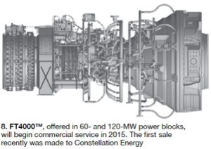
The evolution continues with the recent announcement of the 42%-efficient FT4000™ (Fig 8). The new offering is derived from the P&W PW4000 turbofan engine, more than 850 units strong, which has recorded more than 26 million hours on the Airbus A330 and Boeing 777. The FT4000 is designed for simple-cycle, combined-cycle, and cogen service in 60- and 120-MW power blocks. Full-scale development and testing will be completed this year and commercial service is to begin in 2015. The first FT4000 was sold to Constellation Energy.
PWPS VP Charles Levey was the principal speaker in a special joint session of the P&W and Mitsubishi Roundtables at the CTOTF conference to bring owner/operators up to date on what the Mitsubishi purchase means to the industry. Points made by Levey included the following:
- Global expansion of the aero GT business using MHI resources. The PWPS fleet already counts more than 2000 FT4s and FT8s installed worldwide, including 100 25-MW MobilePacs® for deployment anywhere in the world on short notice.
- Support for the FT4 through its lifecycle.
Details on the expanded Mitsubishi organization are available in Levey’s presentation, accessible to gas-turbine owner/operators through CTOTF’s Presentation Library. Included are slides covering the following topics:
- Field-service capabilities.
- GT vane and blade manufacturing.
- Parts inventory and customer support.
- Remote monitoring center.
- Component inspection and refurbishment services.
- Shop capabilities for rotor repairs and inspections—gas and steam.
- Long-term maintenance and service agreements.
The P&W Roundtable featured two presentations and an open discussion forum. The first speaker, Russ Bell of Vulture Engineering LLC, returned to CTOTF as a vendor after participating in the meeting for several years as a user (Constellation Energy). Bell has deep knowledge of the FT8, gained from 25 years of service at United Technologies—including controls development for the first FT8-1 and FT8-2 engines—and another decade at Constellation.

Bell formed Vulture in 2012 to pursue control system retrofits and automated borescope inspection and reporting. The latter was the subject of his presentation. Bell said Vulture’s “GT Inspect” reduces inspection time and cost, produces reports the same day as the inspection, and provides greater consistency in component inspection than alternative methods.
Inspection data are captured in a series of Excel data input sheets organized by engine module (Fig 9). Data sheets list the components to inspect with each portion of a given component requiring an evaluation identified. Example for the LP compressor module: IGV upper, lower, and root. Next column calls for a “Yes” or “No” for damage, followed by the part number.
Defect measurement is in the next column, followed by the allowable limit; borescope photo number and inspector’s comments round out the entries. Note that allowable limits are entered into the data sheet before the inspection begins. Access Bell’s slides in the CTOTF Presentation Library to see sample data entry sheets for the entire engine.
7F compressor inspections
Advanced Turbine Support LLC’s President Rod Shidler and Field Service Manager Mike Hoogsteden were not on the formal program for the CTOTF meeting last fall, but they did hold an impromptu workshop during the vendor fair on what to look for when inspecting 7F compressors. The duo could talk for hours on this subject but they focused this “class” on the recommendations made by the OEM in Technical Information Letters (TILs) 1509 and 1638; and, in a follow-up phone call, on 1907.
Shidler and Hoogsteden said the company’s technicians are finding that retirements of senior personnel and cutbacks in O&M staffing at many powerplants have significantly reduced the level of knowledge regarding technical information letters—both in terms of the TILs that apply to a given plant’s engines and the actions required by those documents. To be fair, the proliferation of TILs and their updates challenge the abilities of even the most conscientious plant employees to keep current on OEM recommendations.
Compounding the challenge, the two experts said, is that new hires often are unfamiliar with the idiosyncrasies of the engines installed at their plants and may not know, or have access to, all the applicable TILs. Shidler and Hoogsteden recommended that generating facilities experiencing personnel turnover consider reaching out to the OEM’s technical experts for a review of engine particulars and the TILs required.
TIL 1509, “F-class Front-End (R0, S0, and R1) Compressor Inspections,” is important to owner/operators because engine availability and reliability can be compromised by rubs conducive to metal liberation and downstream damage. The inspection experts think some 7F users may be overlooking the finer points of 1509—particularly the recommendation for annual non-destructive inspections of S0 vanes in non-enhanced compressors and in Package 1 and 2 enhanced compressors. These owner/operators believe, incorrectly, that if their engines are not experiencing compressor rubs at R0 and R1 they do not have to inspect S0.

However, trailing-edge cracks in S0 vanes (Figs 10-13) are thought linked to airfoil “lock-up,” which is independent of rubbing. These cracks could result in stator-vane liberation and significant collateral damage to forward and aft compressor stages. Were S0 trailing-edge cracks not considered a priority, the duo asked rhetorically, why would the OEM warn against restarting the machine and recommend replacing the entire stage when cracking is confirmed?

Two more points to ponder when planning the next borescope inspection for your 7F 3-series gas turbine:
TIL 1509 recommends red dye-penetrant for identifying cracks in S0 vanes, but Advanced Turbine Support’s experience suggests upgrading to eddy-current inspection. The reason: It can identify cracks in the initiation phase, before red dye will find them. This allows more time for scheduling the replacement of the vane row.
An S0 inspection is not required by 1509 for unflared F-class compressors. However, Shidler and company have found S0 leading-edge and radial tip cracks in several of these machines.
Regarding the second bullet point, the lesson learned is that simply following the OEM’s recommendations does not assure a healthy machine. Participation in user-group meetings and accepting responsibility for the wellbeing of gas turbines in your plant are critical to success. It’s important to be proactive, not reactive, Hoogsteden stressed, “The more we look, the more we learn.”

The evidence: Fig 14 shows a crack just above the platform of an S0 lower-half vane in an unflared 7F compressor with the stereo measurement tip image in Fig 15. Fig 16 is the eddy-current signal that verified the crack. Fig 17 is the upper-half S0 crack found the week before the CTOTF meeting, with its measurement in Fig 18 and verification signal in Fig 19.

The inspection should be performed only by qualified and skilled technicians. This was recently highlighted by at least one owner who reported that the OEM had given false positives on R0 and R1 rotor blades during two separate inspections. The absence of cracking was confirmed by two third-party inspection firms. Consider getting a second opinion if you question the results. The leading independent inspection firms typically can be onsite within 24 hours.
Hoogsteden said Advanced Turbine Support technicians recently have found cracks below where the OEM suggested inspectors look. Follow a TIL’s recommendations, of course, he said, but go beyond its inspection requirements where appropriate.

TIL 1638 warns owner/operators of F-class engines equipped with standard R0 and R1 compressor blades that the possibility of dovetail distress exists below the platform in the areas highlighted in Fig 20. Users told the editors that fretting at the edge of the contact area in the dovetail is conducive to high local stresses with the possibility of crack initiation. Were cracks to grow to a critical depth, blade liberation might occur. Ultrasonic testing is recommended for identifying root distress.
The inspection should be performed only by qualified and skilled technicians. This was recently highlighted by at least one owner who reported that the OEM had given false positives on R0 and R1 rotor blades during two separate inspections. The absence of cracking was confirmed by two third-party inspection firms. Consider get-ting a second opinion if you question the results. The leading independent inspection firms typically can be onsite within 24 hours.
Hoogsteden said Advanced Turbine Support technicians recently have found cracks below where the OEM suggested inspectors look. Follow a TIL’s recommendations, of course, he said, but go beyond its inspection requirements where appropriate.
TIL 1907, “Rotor Forward Shaft Dovetail Crack,” issued by GE about a month after the CTOTF meeting, concerns cracking of dovetails in the R0 disc at the edge of contact between the blades and the wheel. Shidler and Hoogsteden called to say it was important for users to review the document as soon as possible, adding that it is not easy describe in a few words which of the many variations of 7FAs are affected, so the first thing to do is to get the TIL and figure out if you should be concerned. Photos within the advisory provide encouragement to be proactive, they said.
One owner/operator mentioned R0 dovetail cracking during the GE F-class Roundtable at the spring 2013 CTOTF meeting in Myrtle Beach, SC. There wasn’t much discussion on the topic because no one other than the affected user had heard about this type of failure. Turns out, it was the first such incident reported publicly. By the time the fall conference took place, another failure of this type had been reported and there was a high level of interest among attendees.
Relatively little was said about the issue during the OEM/owner session of last fall’s GE F-class Roundtable, but the subject got more air time in the user-only portion of the program. Serendipitous was how the owner described the original finding in the fall of 2012: The upper half of the compressor was exposed to accommodate other work when someone looked down and noticed a crack in one dovetail. Actually, there were cracks in several of the 32 dovetails, on the suction side of the wheel. Chilling. The rotor was pulled from the unit and shipped to a GE shop where the forward shaft was replaced. There is no procedure for repairing disc cracks at this time.
The affected machine had been re-equipped with the latest OEM R0 blades—stronger airfoils, beefed-up platforms, etc, to address fleet issues and improve durability. The blades were fine. Informal discussion among users pointed at the following possibility: Stresses in the new blades when passing through critical speeds during engine starts are transferred to the dovetail region of a wheel that might have benefitted from more conservative design.
It would appear that the OEM believes units in peaking or cycling service are more susceptible to R0 dovetail cracking than base-load machines, users told the editors, given the inspection intervals specified in TIL 1907. An ultrasonic inspection is recommended every 900 factored fired starts for starts-based machines; 48,000 factored fired hours for hours-based gas turbines.
Inspections can be conducted in-situ, according to Shidler, and in one shift using the phased-array ultrasonic inspection technique. CCJ