
Recognized for Best Practices in O&M, Safety, Workforce Development, Outage Management
 Foam inserts prevent air flow through offline gas turbines
When gas turbines (GT) are shut down for extended periods in Georgia, the high humidity and natural draft through the HRSGs creates problematic condensation on tube fins. Rusting occurs, especially when water is still present in the tubes. Ultimately, excessive tube fin rust creates a resistance to exhaust flow through the HRSG and GT back pressure increases, reducing turbine output.
The staff at Effingham County Power, a 2 × 1 F-class combined cycle managed by Nick Bohl, investigated adding stack dampers, duct balloons, and compressor inlet foam inserts to minimize air flow through the HRSGs. The most effective option would have been stack dampers, but their upfront and ongoing maintenance costs were significantly higher than those for the alternatives. The duct balloon was an interesting and feasible option; however, the time and manpower required for balloon deployment and removal militated against its selection here.
The most economical and effective solution for Effingham, which is owned by The Carlyle Group and operated by Cogentrix: High-density, custom-fitted foam inserts (photo), which prevent air flow through the compressors and HRSGs. Cost of the inserts for both turbines was under $9000; no maintenance is associated with this application.
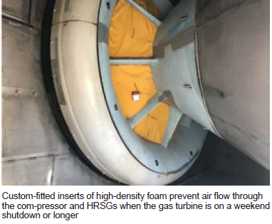
The inserts were labelled for each unit for inventory purposes. A LOTO is placed on the unit when the inserts are installed to ensure accountability. Once the inserts are removed and counted, a shift supervisor performs a close-out inspection of the GT inlet.
Results from using the inserts are impressive: GT wheel-space temperatures remain above 150F 90% longer using the inserts versus not installing them for a weekend shutdown. Also, HRSG internal temperatures remain above 100F 40% longer with the inserts.
The trapped heat helps minimize condensation on HRSG piping and components. Once the HRSG temperatures are low enough and a dispatch is not expected, the HRSGs are drained. This practice is expected to help reduce corrosion and minimize performance issues.
Installing inserts on Friday following a shutdown saves fuel and increases revenue by allowing faster ramping when the units are restarted on Monday. This is based on less time needed to warm components and quicker steam formation because HRSG drums and piping retain heat longer.
Streamlining I&C learning
Effingham’s web-based I&C training program is supported both by a training bench with various plant instruments for hands-on experience and a supervising subject-matter expert. The plant SME is responsible for training technicians on the software and the test and monitoring equipment they will use on a daily basis.
The existing web-based training program was considered inadequate because it included outdated monitoring and test equipment which was not plant-specific, delaying the qualification process because of a lack of reference material and available training lessons.
Without reading the actual O&M manuals there was nothing in place to prepare technicians for hands-on training or instrumentation calibrations. And without actual test equipment and monitoring-device training there was limited reference material. Once the technicians were qualified they had to rely on their notes and read the O&M manuals to complete the required proficiency training.
Aiming at a solution, the I&C SME developed a list of things technicians need to know to become proficient in calibrating Effingham’s instrumentation. This information in hand, the web-based training courses were evaluated for their applicability to the plant’s mission. The most pertinent courses were grouped into eight modules.
Fourteen PowerPoint presentations then were created to train individuals on plant-specific instrumentation, calibration equipment, calibration software, and proper calibration techniques. These presentations were reviewed by qualified I&C techs for content and effectiveness and then added to the eight web-based training modules to form a structured plant-specific I&C fundamentals training program.
Exams were created to help reinforce the knowledge learned. Job performance measures (JPM) also were developed to evaluate the technician’s ability to perform calibrations on various monitoring devices. Since the SME uses these JPMs to certify the technician’s abilities, each individual is evaluated using the same standard.
The streamlined, updated program is highly regarded for the following reasons:
-
- Covers more areas of I&C than previously, producing better-trained technicians.
- Provides self-guided reference materials, which allow the technician to build confidence and education to ask the right questions. This helps both the SME and the qualifying technician.
- Has a training bench that allows technicians to practice calibration techniques online or offline rather than in the plant, minimizing the possibility of lost generation.
Finally, as new test equipment is purchased, training presentations and exams are developed and implemented. The training program is continually evaluated for its content and ability to train plant personnel. Since Effingham owns the training program it can be revised as needed at minimal cost.
Outage management improves with delegation of job leads
In the past, contractors interacted only with the maintenance supervisor and/or shift supervisor when onsite for outages. This created bottlenecks because each contractor needed to meet with the same one or two individuals to receive plant support—such as having LOTOs in place, preparing hot-work permits, inspecting work areas, retrieving parts and materials for the job, etc.
Significant man-hours were wasted while each contractor waited its turn to speak with the one or two management personnel conducting the outage. Since Effingham’s outages are necessarily brief, staff discussed ways to streamline the process and maximize contractor productivity.
Once the maintenance supervisor has awarded the job to the contractor, a technician is assigned as the contractor’s job lead. The technician typically is selected based on his or her subject-matter expertise. It is important for this individual to adequately support the contractor and to understand the basic job scope.
The expectation is for the two parties to communicate by phone or email prior to the outage to discuss the job and how it will be completed. Once the job lead understands the scope of the job, the plant can prepare for the contractor’s arrival.
Onsite, the job lead and contractors meet and the job lead ensures the safety orientation has been completed. The job lead is responsible for ensuring the LOTO is walked down with the contractor and if there are any discrepancies, they are resolved prior to the workers signing onto the LOTO. If any confined-space or hot-work permits are required, the job lead makes sure they are in place each day the contractor is onsite.
The contractor and job lead meet daily onsite to discuss the day’s plan and job status. If the contractor needs any parts or materials, the job lead is contacted and those items are delivered to the appropriate location. The contractor doesn’t lose man-hours searching for help, it just contacts the job lead to get the needed support to complete the job on schedule.
This process proved valuable while conducting a major outage in 2016, in which Effingham had over 350 contractors onsite. When the contractors arrived, they exchanged phone numbers with their job leads (if they had not done so already), and when assistance was needed, it was necessary to make only one call and never leave the worksite.
Proper greasing protects bearings, reduces maintenance cost
To reduce motor repair costs and avoid possible lost generation, plant had to improve its method for greasing large frame motors. Effingham’s local motor repair shop reported that several motors sent for repair had little to no grease in their bearings. Typically, all bearings were receiving the same amount of lubricant; however, lubrication should be based on bearing size and the manufacturer’s recommendations. A system of greasing bearings that took into account these differences was necessary.
The proper amount of grease for any given motor or bearing was found by using the motor and bearing manufacturers’ data sheets, in addition to information available on the motor data plate. Nameplate data on most motors include bearing identification numbers which can be cross-referenced to reveal bearing size, configuration, and lubrication requirements.
Personnel also measured the output of the plant’s grease guns by weighing the grams per pump to determine how many pumps per gun it would take to achieve the recommended amount of grease per application. Once they knew how much grease the gun applied per pump, staff calculated how many pumps it would take to provide the required amount of grease in a given application. Labels then were affixed to the grease guns to provide the information required by technicians performing the lubrication PMs.
Next, technicians stamped stainless-steel tags—they resemble dog tags—with the lubrication information and attached them to the motors with stainless-steel chains. Having this information right on the equipment saves time and ensures the proper type and amount of grease is used.
Proof of success: When performing operator rounds, a technician discovered that a cooling-tower fan motor had some bearing noise. He added grease based on the old method of one to two pumps from a grease gun. Several technicians then researched the amount of grease recommended by the bearing manufacturer. As a result of their investigation, more grease was applied and the problem was resolved. Since program implementation, technicians have performed several successful greasing PMs.
Standardizing data on fire extinguishers benefits recordkeeping, compliance
The date of manufacture is required on fire extinguishers, but there is no standard format or location on the bottle for this information. Some extinguishers are labeled on the bottom, some have the information mixed with other data in code on the bottle, and some have the date on the printed label, which fades and peels in outdoor applications. The manufacture date is required to establish requirements for six-year inspections and periodic hydro testing mandated in NFPA regulations.
Personnel contacted various manufacturers to identify the location and format of the manufacture date on their extinguishers. Embossed metal tags were added to each fire extinguisher on the hose or neck, identifying the later of the date of manufacture, date of last six-year inspection, or date of last hydro test. Date information also was added to the fire-extinguisher inspection checklist for annual inspections, to aid in identifying periodic maintenance requirements.
Benefits are ease of inspection and recordkeeping, simplified maintenance procedure, and assured compliance with applicable NFPA requirements. Labor cost also is reduced because it’s now easy to find this information when performing monthly and annual fire-extinguisher inspections. Plus, budgeting is more accurate knowing when the fire extinguishers will be serviced.
Color coding helps identify proper oil for a given piece of equipment
Plant was having difficulty maintaining labels on secondary oil containers. The markings were fading or the labels would come loose and fall off because of contact with the oil. Proper fluid identification is important to avoid contaminating oil used in other equipment. Cross-contamination can lead to premature wear or even catastrophic failure.
Because several different oils are used in the plant, a procedure was needed to ensure the correct oil was added to each piece of equipment. In the past, the auxiliary operator would look up which oil was required when finding a low oil level during rounds. Plant needed a way to ensure the correct oil was added; also, to expedite the process to ensure bearings were lubricated properly.
The optimal solution was to assign each type of oil a specific color code. This color then was painted on the storage container used by operators to replenish oil lost during operation as well as on the fill ports of the equipment requiring that particular oil. Since these containers were used for only one type of oil, a durable laminated tag was attached to the handles so the oil could be stored and used as needed.
Today technicians do not have to clean containers prior to use because the labels are securely attached, and the contents properly identified, minimizing waste. Cross-contamination of oils is avoided by verifying that oil is added to the proper secondary containers by reviewing the labels.
Technicians use the preventive-maintenance work order and lubrication chart to verify the proper oil needed for a given piece of equipment. Having the ability to verify the same color on the container and the fill port is a good back-up check.