
Presentations by Shuman, Tucker get meeting moving on a fast track
Knowledgeable opening-day speakers passionate about the technologies in their fields of expertise are critical to the success of user-group conferences. They stimulate thinking and discussion that can keep participants energized until the closing bell. The steering committee (sidebar) for the Frame 6 Users Group invited two of the industry’s best—Alfred Shuman and Paul Tucker—to participate in its 2012 Conference at the Hyatt Regency in Greenville, SC, June 25-28.
Shuman, a senior consulting engineer for PAL Turbine Services LLC, Clifton Park, NY (near Albany), and Tucker, the founder/president of First Independent Rotor Services of Texas (FIRST), Humble, Tex, are experts on GE legacy frame gas turbines with decades of hands-on experience each.
Both presenters had their challenges and both handled them well. Shuman’s presentation, “When Bad Things Happen to Good Turbines,” focused on damage suffered by machines primarily because of carelessness and a poor grounding in fundamentals. With half the audience first-timers and the other half hard-nosed senior O&M personnel, you can see Shuman’s dilemma: How to hold the attention of attendees with deep experience during a “basics” presentation that left some others with a “wow” look.
But the consulting engineer is a teaching pro who moved quickly through the material and kept the users engaged with a steady stream of questions that piqued the interest of the experienced, some concluding they didn’t have all the answers.
Tucker’s primary challenge was being the first speaker after a relaxing lunch. Tough to recapture the morning’s energy, but he is one of the industry’s top rotor experts and this group has many high-hours engines. So attendees representing units in cogeneration service, in particular, wanted to learn about turbine-rotor end-of-life evaluations.
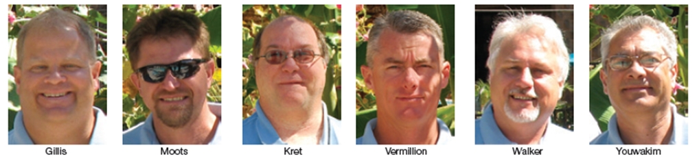
2012 Steering Committee
Co-chairs:
- Jeff Gillis, ExxonMobil Chemical
- Sam Moots, Colorado Energy
Members:
- Geoffrey Kret, Total Petrochemicals USA
- JC Rawls, BASF (Gelsmar)
- John Vermillion, Atlantic Power Corp
- Brian Walker, Foster Wheeler Martinez Inc
- Zahi Youwakim, Huntsman Corp
Note that the Frame 6 Users attracts more O&M personnel from the energy-intensive process industries than any other gas-turbine user group. For example, participants at this year’s meeting included representatives of Total Petroleum, Chevron, Shell, Foster Wheeler Martinez, Huntsman, BASF, Formosa Plastics, ExxonMobil, LyondellBasell, Berry Petroleum, etc.
Good turbines, bad happenings
Shuman began by reminding the owner/operators that no one is immune to making mistakes and that review of past errors helps keep you on your toes. Perhaps no one in the room knew this better than the speaker, who started his career as a machinist’s mate on the USS Nautilus (SSN-571), the world’s first nuclear submarine, more than four decades ago.
Shuman can talk “mistakes” for hours on end from personal experience and because he has access both to PAL Turbine Services’ extensive files on equipment dos and don’ts dating back half a century and to its silver-domed staff of 15, only two of whom have fewer than 30 years of industry experience. Judging from the employee resumes at www.pondlucier.com, many knowledgeable retirees build rewarding second careers at PAL. If you get to the site, visit “Turbine Tips” for a catalog of best practices and “The Turbine Cowboy” to share field engineering experiences.
Bolting. The retired sailor’s fourth slide had the headline “WWII Liberty and Victory Ships.” Everyone realized at that point, Shuman wasn’t your typical industry speaker. By show of hands, about half the attendees said they had no familiarity with Liberty and Victory ships (too young, obviously), the first all-welded merchant vessels to serve in the war effort. The takeaway from the ship experience was the failure of many welds attributed to embrittlement—caused, in large part, by contaminants and excess hydrogen in welds.
The combustion-can cover, complete with fuel nozzle and pigtails, launched when bolts failed because of embrittlement. The missile blew off the combustion compartment door, and the large pressure differential created when the cover went airborne caused the liner and flow sleeve to collapse.Shuman’s message had nothing to do with ships or welding, but rather to the use of cadmium- and zinc-plated bolting. Don’t use cadmium-plated bolts in the combustion, turbine, or exhaust sections of your gas turbine, he said. Above 450F, the cadmium melts and attacks the grain structure of the bolts and they fail. The failure mode is called “liquid-metal embrittlement,” which is similar in nature to hydrogen embrittlement.
Rusted bolting in turbine air-inlet ductwork can harm compressor components. Shuman couldn’t figure out how to get his favorite photos of ships at sea in this segment of the presentation, just several pictures of compressor damage from failed ductwork bolts. The ex-sailor stressed the need for first-class hardware and its proper installation to prevent bolts from going downstream into the compressor.
Ductwork must be inspected and maintained regularly, Shuman said. Holes in the rusting metal allow water and foreign material to enter the inlet house and get sucked into the compressor. Bolts holding sections of ductwork in place are inserted from the outside, he continued, with nuts on the inside tack-welded to their respective bolts. Any water leaking along a bolt, which is virtually impossible to see, eventually eats through that bolt allowing the nut and part of the bolt to enter the air stream. Your maintenance plan should include sealing of bolt penetrations as well as repair/repainting of rusting ductwork.
Shuman pointed to the inlet bellmouth in a cutaway slide and told the group that the pressure drop in that area increases air velocity to Mach 0.5, so any material entrained in the air stream goes into the compressor with conviction. He also mentioned that the delta P across the inlet throat produces a 23-deg-F drop in air temperature. This is why you can have icing and associated compressor-blade damage when the ambient temperature is above freezing.
Cautions with open casings. Ask labor to tell supervisors when tools, parts, or other foreign objects fall into open casings.Everyone knows this, but the message must be reinforced daily during outage reviews, Shuman said. “Stress that no one will be fired or censured, as long as the incident is reported promptly.” He then offered two case histories of when bad things happened because of the failure to remove tools from inside the engine after an outage.
Shuman said that the high compressor discharge pressure was caused by a tightening of the nozzle throat area because of FOD. He pointed out that the nozzle throat is the tightest orifice in the HGP and that even small deviations from its critical dimensions can upset engine behavior. The speaker offered a diagram of the nozzle throat area with dimensions that should be verified by owner/operators or their contractors.In the first incident, the output of a 7EA following a hot-gas-path (HGP) inspection was significantly less than before the outage. Compressor discharge pressure was higher than expected. Testing indicated a problem in the turbine section. Note that a portion of the trailing edge of one first-stage nozzle partition was missing. The damage looking upstream from behind the first-stage buckets. Another view of the missing section of trailing edge and shows how the trailing edges of other vane partitions have been pushed upstream by the foreign object.
The control system, reminded Shuman, relies on readings of several variables—including ambient-air and exhaust temperatures, exhaust spreads, and compressor discharge pressure and temperature—to tweak unit operation. When the data imported don’t match what the control system expects, it makes adjustments. In this case, the control system reduced fuel flow because the damage had restricted air flow through the unit.
The missing bullnose and the denting of the leading edge of the first-stage bucket highlighted Fig 5B were caused by FOD. Examination revealed that one or more foreign objects tore through the nozzle partition and then banged up some first- and second-stage buckets.
“Splatter” created by the thermal and physical destruction of FOD and liberated HGP components deposited on first- and second-stage buckets. Metallurgical analysis revealed multiple materials in the splatter; one was tool steel which had no business being in the engine. The “ah ha” moment came when the outage manager remembered that feather wedges used to align the combustion liners and transition pieces were made of tool steel. They had not been removed, as specified, before the engine was buttoned-up.
Second incident. A Frame 6B, restarted after a major overhaul that included replacement of all HGP parts along with a refurbished CDC (compressor discharge case) inner barrel, was expected to show a significant improvement in unit performance. Instead, plant personnel saw a reduction in power output of about 9%. Tuning and other adjustments did not help.
Performance tests were conducted and a borescope inspection ordered. Results of the latter were disturbing. Splatter was found on the pressure side of some first-stage buckets, near their platforms. Melted metal also had been sprayed on the leading edge of the second-stage bucket shroud. The engine was opened immediately.
Severe gouging was found on the inside of the inner barrel and the rotor was banged up.
Splatter on the first-stage buckets was easy to see with the machine open. Analysis of the splatter revealed material from the inner barrel and an unknown foreign object. Best guess as to what the foreign object was: A hammer!
Accurate clearance measurements are critical to avoiding bucket rubs and consequential damage caused by rubbing. The effects of out-of-round turbine casings and too-tight turbine clearances are the root causes of rubs, which typically occur at slow speeds during the first start after an outage.
As the heat of friction causes metal to melt, globules high in carbides are formed. The hard carbides contribute to more rubbing with the rails on some bucket shrouds being completely worn off. When this occurs two things happen: (1) The shroud structure is weakened, and (2) sealing is compromised and gas bypasses the buckets, reducing performance.
Shuman suggested that some owner/operators may not fully understand the true costs of tradeoffs made during reassembly. “To measure is to know,” he said emphatically. Even if you are going to change out turbine nozzle partitions and buckets during an outage, it’s important to check all internal clearances after opening the unit and again before closing it.
Turbine, compressor, and bearing clearances are where the “rubber meets the road,” he added. The OEM’s design engineers view clearance diagrams with their specific tolerances as the bible for establishing performance and reliability parameters. Shuman stressed that the person taking the clearances must have a good understanding of how and where to take accurate measurements, recognizing that this task is one of the most important of the outage.
One of his shocker topics was the Frame 6B bucket shroud-lift phenomenon. Some attendees were not aware that legacy second-stage buckets, in particular, are prone to creep and if operated unchecked might grow to a destructive length. Ignore the OEM’s recommendations at your own risk. Experienced speakers, especially ones working their way through multiple technical topics, know their audiences begin to tire after a half hour or so of “lecture,” despite repeated attempts at humor. How to recapture the attention of listeners can be challenging. Shuman used the “shock” technique—few words and lots of pictures of damage no one wants to see when they open their unit.
Terse lead-in to this topic: Unit was open for an HGP inspection; owner chose not to the follow the OEM’s TIL (Technical Information Letter) recommendation to change to new buckets because of potential cracking on airfoils. Instead, the user repurposed a set of buckets from another unit at the site which had marginal shroud-lift readings.
The unit looked like at the first outage, after saving money by not buying new turbine parts. Note that R1 buckets are only lightly damaged, but the second and third stages were chewed up badly. Plus there was collateral damage to the exhaust-frame outer barrel. There were more photos as well, most close-ups of ugly metal. Attention regained.
Reconsider eliminating the plant chemist position. Everyone is under pressure in the highly competitive power generation business: Cut people, reduce expenses, produce more kilowatt-hours. Plant chemists are an easy target for elimination: They can’t operate the plant from the control room, they never have a wrench in hand. What do they do, anyway? Now ask yourself, “What does a fireman do when not putting out fires? Please read the article in this issue, “Minimize operational risk with an onsite chemist.”
Corrosion was Shuman’s next topic. He told that group that contaminating reagents can enter the hot gas path via ambient air, fuel (both oil and gas), evaporative cooling, etc, stressing that contaminants from all sources are additive in concentration and impact. The contamination example he presented illustrated the importance of water chemistry in maintaining a healthy GT environment.
Simply put, steam injected for NOx control was attemperated before it entered the turbine to reduce combustion-zone temperature. Water for attemperation was provided from the condensate/feedwater system which contained the oxygen scavenger hydrazine.
A “hydrazine event” allowed an excessive amount of the chemical to enter the gas turbine where it leached out cobalt in the airfoils and turned first-stage buckets and nozzle partitions to scrap. The characteristic blue color of cobalt oxide. A seasoned chemist might have avoided use of oxygen scavengers altogether, as recommended by many experts in the field, or at the least had the appropriate instrumentation in place to warn of such an event.
Haste makes waste. This phrase can be traced to biblical times, so it’s apparent that the human species is a slow learner. Shuman’s last “lesson” concerned an overhaul team that thought it wise to rush the back end of a 6B major “to meet the schedule.”
Repair of the resulting damage took 10 times the hours it would have taken to do the job properly the first time. Cost of the extra field labor hours and outage time were in addition to the cost of repaired and replaced compressor components. Photos revealed where retaining keys should have been locked in place, rubbing damage was experienced in the dovetail slot—caused by rotation of blade rings in service. Rubs and dings also were found on blades and vanes—a cornucopia of issues.
Wrapping up, the overhaul expert advised that if schedule is causing an inordinate rush, stop to think, review the situation, and act accordingly. Don’t make mistakes that are avoidable; work safely, work smart. Following good engineering practices always trumps false economy, he stressed. Finally, account for every single tool and every part before closing up the GT. Then, before starting the engine, conduct a borescope inspection “to be sure.”
End-of-life inspection
For readers unfamiliar with the Frame 6, the fleet was launched in 1978 by General Electric Co with the 31-MW MS6001A. To date, the 1200-plus units shipped worldwide by the OEM and its manufacturing associates for either 50- or 60-Hz power generation service have accumulated more than 60-million operating hours. Most engines serve in simple- and combined-cycle configurations, but a significant number also underpin cogeneration systems. OEMs tell users their gas turbines have critical parts with finite lifetimes and that replacement of these parts may be necessary to assure reliability and safety moving forward. Rotors are a primary target of this initiative. Today, the only way to determine if an ageing rotor is in sufficiently good condition to continue operating is to disassemble it and to nondestructively examine (NDE) individual wheels, bolts, etc.
Industry shorthand refers to the engine as the “6B,” only nine “A” models having been built. The first “B” that went into operation 31 years ago reflected a 5.7-MW increase in output over the first “A” and a 170-deg-F increase in firing temperature to 2020F. After four model upgrades, the PG5681B offered today is rated 41 MW at a firing temperature of 2084F. This design is now 12 years old. From the beginning, the single-shaft, two-bearing unit has employed a 17-stage compressor and three-stage turbine.
A focal point of the 2012 Conference was rotor lifetime assessment, a subject that has been on the Frame 6 Users’ program for the last couple of years. Several owner/operators active in the group have engines north of 150,000 hours and wanted to know what they should be doing to meet the intent of the OEM’s TIL 1576, issued in 2007.
The document requires rotors with 200,000 equivalent operating hours or 5000 equivalent starts (whichever comes first) to undergo a comprehensive inspection. Hours-limited rotors that pass inspection, with or without rehabilitation or replacement of critical parts, can be certified for extended service (50,000 or more hours). The OEM’s current position reportedly is that rotors having accumulated 5000 starts are at end of life no matter how good they might look.
The steering committee, co-chaired by Jeff Gillis of ExxonMobil Chemical and Sam Moots of Colorado Energy, incorporated into this year’s program a comprehensive and balanced look at rotor life management. It included the following:
- A formal presentation by the OEM on the subject.
- A special GE roundtable on compressor and gas-turbine life management.
- A user’s experience with the OEM’s rotor lifetime assessment process.
- A third-party service provider’s methodology for, and experience in, conducting rotor end-of-life inspections.
The user speaking on his company’s experience with GE’s lifetime inspection service began with a backgrounder on the equipment inspected and the scope of the inspection. His plant’s three 6Bs were commissioned in 1989 and had accumulated 180,000 fired hours in base-load service on natural gas using steam injection for NOx control.
First step in the inspection process was complete rotor disassembly. Next came nondestructive examination (NDE) of CrMoV steel wheels installed in the turbine and aft compressor (rows 14-17), and the distance piece. Inspection efforts focused on dovetail slots, rabbets, wheel bores, and bolt holes. Ground rules specified that all indications found had to be evaluated by the OEM’s engineers. Those evaluations might allow continued use as-is or require blending, repair, or component replacement.
The user purchased a new rotor and installed it in Unit 1. The original Unit 1 rotor was installed in Unit 2 after inspection and refurbishment. The Unit 2 rotor, in turn, was installed in Unit 3 after it was inspected and refurbished. A decision regarding the disposition of the original Unit 3 rotor is pending. The speaker said the OEM’s schedule for the end-of-life (EOL) assessment typically is nine weeks, broken down as follows: two to three weeks for de-stack and clean-up; two weeks for the EOL inspection; three to four weeks for reassembly, assuming only minimal machining is required to correct any minor deficiencies identified.
The user next presented inspection results for one unit to give his colleagues a view of the types of NDE techniques employed and the level of detail sought. Here’s what he said:
- Visual inspection and replication. Pitting was found in the bore from the compressor 16th stage through the second-stage turbine wheel, but it was not life-limiting. No microcracking or variations in grain structure were identified. Corrective action: Bore surfaces were reconditioned/honed to eliminate stress concentrations and bore fatigue damage.
- Magnetic particle inspection of each component produced no findings.
- Hardness readings all were within the OEM’s serviceable tolerance ranges; no concerns.
- Ultrasonic testing of bore surfaces of all components covered in the scope of work produced no limiting findings. Some indications were found imbedded into the distance piece. They were considered “birth defects.” Fracture assessments determined no anticipated propagations to failure within 750 starts—decades of useful life for a base-load unit.
The bottom line: The OEM certified this rotor for 750 total starts and 300,000 equivalent operating hours.
FIRST’s Tucker. The third-party view on EOL inspections was provided by Paul Tucker and Gary Hensley, an NDE expert affiliated with Veracity Technology Solutions, Tulsa. Both were principals in the first third-party consortium to conduct EOL inspections of GE frames following the release of TIL 1576. Some believe Tucker, who worked in GE rotor shops for more than two decades before striking out on his own, and Hensley may have done their first Frame 7 EOL inspection before the OEM. Results of this inspection are profiled in the Frame 5 report, p 78.
The pair discussed ongoing work in EOL inspections, which at the moment, focuses on several Frame 5s. Tucker pointed out that while he and Hensley had not yet conducted a lifetime assessment of a Frame 6 engine, this machine is similar in many respects to the Frame 5s and 7s they have done.
Inspections conducted by FIRST/Veracity to determine if an engine is fit for duty include the following:
- 100% three-dimensional boresonic inspection for internal flaws.
- Eddy-current inspection for creep.
- Hardness and replication for grain structure.
- Critical diameters measured for bore shrinkage.
- Finite element analysis (FEA) when flaws are identified.
Regarding the last point, FIRST and associates have developed rotor-component fracture models to perform FEA analyses when needed. Tucker said that FIRST’s critical flaw size and fatigue life estimations enable the company to analyze flaws with its models to see if flaw characteristics are detrimental to machine operation. He said the models can determine if specific flaws will fail, and if so, when in terms of hours and/or starts.
Inspections conducted by FIRST/Veracity nominally take five days; however, analysis of any flaw that might be found can add a couple of weeks or more to the schedule. It was at this point that Tucker suggested to the Frame 6 owner/operators that they do an EOL inspection earlier rather than later—during a major or when you’re going to replace compressor blades, he said.
Having a baseline condition assessment enables users to better manage the lives of their rotors. Plus, if it appears that one or more components will have to be replaced in the future, knowing earlier allows owner/operators to plan for that eventuality and to order refurbished or new parts on a standard delivery schedule.
A question from the floor: If you do not find defects during an EOL inspection, how long will the rotor last? Tucker responded by saying that creep life is the user’s greatest concern and asked rhetorically, “What margin of safety is built into the hours and starts numbers specified in TIL 1576? A factor of two, perhaps?”
The robust coverage of EOL inspections at the 2012 Conference reflected the group’s interest in the subject at the previous meeting in Scottsdale, Ariz. There Greg Snyder, director of engineering for Dresser-Rand Turbine Technology Services (D-R TTS), Houston, and Rich Curtis, VP engineering for Eta Technologies LLC, Coventry, Ct, outlined a rotor life evaluation program that their companies had developed jointly.
Of course, some owners will just accept the OEM’s hours and starts EOL limits and purchase a new rotor. Snyder acknowledged that a new rotor is the path of lowest risk, but it is the highest- cost option and the commitment lead time is considerable.Perhaps the greatest value of the Snyder/Curtis presentation was the checklists it provided users responsible for managing rotor evaluation programs. The checklists can assist in evaluations of the various service providers—including the OEM and third-party shops like D-R TTS. They also can help in writing specifications: You don’t want to forget something important because you “didn’t know.”
He next described the process the D-R TTS/Eta Tech team uses to enable retire/restore/replace decisions. It begins with customer inputs, critical for evaluating the impacts of prior and projected future operation. Here’s some of the information you will be asked to provide:
- Operating hours: base load, part load.
- Starts: number and type (slow, normal, fast).
- Trips/load rejections.
- Shutdown time between restarts.
- Ambient environment data—for example, temperature, air cleanliness, location downstream of cooling tower plume, close proximity to saltwater, etc.
- Operating paradigm—for example, seasonal.
- Design configuration.
Assuming you have the requisite experience to have the turbine rotor removed from your gas turbine and shipped to a qualified repair shop with the capability for proper disassembly, you should come up to speed on the various inspections (and reasons for them) and engineering assessments necessary for decision-making.
Many detailed parts inspections were recommended by Snyder and Curtis, some requiring special skills in nondestructive examination (NDE) and metallography. They next reviewed the key considerations for the rotor-lifetime-extension inspections, including:
- Rotor construction.
- Original manufacturing and inspection processes and accept/reject criteria for the latter.
- Alloys of construction and original heat treatments.
- Failure/damage history for your turbine model (fleet) and your unit.
The inspection team you engage will “worry” about residual subsurface flaws from the manufacturing process, small subsurface defects linking to critical flaw size under low-cycle-fatigue (LCF) loading, creep damage, metallurgical changes over time, and the effects of prior “events” experienced by your unit.
Inspection tools include state-of-the-art volumetric ultrasonic testing using phased-array probe technology, advanced three-dimensional signal processing, and digital data archiving; plus, eddy current, fluorescent magnetic particle, visual, dimensional, metallurgical, and hardness measurements.
Critical areas to inspect include:
- Wheel bore regions.
- Bucket dovetail fits.
- Bolt holes.
- Bolt-circle contact faces.
- Rabbet fits.
The engineering phase of the rotor evaluation effort uses established analytical processes and methods for life assessment. Probabilistic evaluation also is part of this effort to assess sources of variation and the risk of a missed defect during the next interval. Engineering capabilities of the firm you select should include reverse engineering, finite element analysis (thermal and mechanical), materials testing and characterization, and analysis of LCF, creep, and crack propagation.
An assessment of in-shop repair capabilities—weld processes in particular—also should be part of your due diligence effort.
Optimal tip clearance
The segment of Alfred Shuman’s presentation on damage caused by bucket rubs was a fast-moving alert for attendees (refer back to Fig 9), more than half of whom had not attended Lloyd Cooke’s presentation on subject of tip clearance at the 2011 meeting. Cooke, an expert on hot-parts repairs at Liburdi Turbine Services Inc, Dundas, Ont, Canada, told the group that excessive turbine-bucket tip clearance raises your fuel bill because of lost performance, while insufficient clearance increases the cost of maintenance. The goal, he said, is optimal clearance.
Cooke noted that a gap of 40 mils between bucket tips and shroud blocks decreases power output by 1%—or about 400 kW for a typical 40-MW Frame 6B. This could penalize a base-load engine $100,000 annually, possibly more, depending on the cost of power.
Perhaps the best way to optimize tip clearance, Cooke continued, is to specify a high-strength casting (single crystal or directionally solidified alloy) for first-stage turbine buckets and apply an “engineered blade tip” of different material during airfoil manufacture. The latter is designed for superior oxidation resistance and sometimes contains embedded abrasive particles to grind into abradable coatings on shroud blocks, thereby creating the optimal clearance. The tip is applied as a powder metallurgy or sintered pre-form material and fused to the tip in a vacuum furnace.
It’s not uncommon for a turbine bucket to suffer rub wear and high-temperature oxidation at the tip, Cooke told the group. Original alloys and conventional coatings are unable to prevent oxidation in high-performance engines. To compensate for metal loss—which can open tip clearances by as much as 30 to 60 mils—application of an oxidation-resistant weld alloy was recommended by the metallurgist.
He suggested a nickel-based alloy with higher aluminum content than the original casting—specifically Liburdi’s L3667, which is applied using an automated welding process. More than 15 years of experience with this material, Cooke said, shows repaired buckets can achieve a full 24,000-hr service interval with no metal loss. Buckets then are repairable for additional service—possibly up to more than 100,000 hours.
To minimize second- and third-stage clearances, he presented the details on the company’s honeycomb seal mod for outer shroud blocks and the advanced cutter teeth it welds to buckets. These solutions have been used by Liburdi on 7EA and 7FA engines.
Cooke pointed out some of the deficiencies of the OEM’s original cutter-tooth design, which was conducive to friction heating of the rail and transfer of rail material to the honeycomb seal. He showed how the Liburdi pre-grooving solution with a Stellite cutter installed on one quarter of the buckets provided sufficient clearance between honeycomb and rail on both sides and top surfaces to prevent overheating.
Next topic: Shroud blocks.Mature engines suffer turbine-casing distortion over time, Cooke said, and Shuman reiterated. Casing radial dimensions, and tip clearances, are tighter at split lines because of the rigidity of bolting flanges. Inspections reveal that shroud blocks at top and bottom dead center usually are not rubbed because there is excessive tip clearance at these points and close to them.
Thus, the strategy of simply restoring bucket tip heights is defeated by shroud rubs incurred because of out-of-round casings. The Liburdi solution here is to tailor shroud-block thicknesses to accommodate casing distortion by forming a close-to-cylindrical arc for the turbines blades. Cooke explained how casing measurements are taken to determine shroud-block radial adjustments.
The composition of shroud coatings was the final subject of the presentation, which had not been reported on previously by the CCJ editors. Early shroud-block coatings, Cooke said, were dense MCrAlY or ceramic thermal barrier coatings (TBCs). Both were not truly abradable and contributed to bucket-tip metal loss when there was contact between the airfoils and the shroud.
Today’s shroud coatings typically are abradable—that is, friable and sacrificial during a rub. But they must be oxidation resistant as well. High-porosity TBCs applied by air plasma spray can be used for internally cooled F-class blocks. But they are not appropriate for uncooled E-class blocks because of their high hardness.
A high-porosity MCrAlY top coat applied to uncooled E-Class blocks by air plasma spray is recommended because it is both abradable and oxidation resistant. The first part of the two-part coating consists of a MCrAlY bond coat for oxidation resistance and adhesion. The 25% to 35% porosity top coat is achieved with polyester sacrificial fill.
HRSGs, steam systems
Frame 6 meetings dig deeper into heat-recovery steam generators (HRSGs), and steam systems in general, than any of the other model-specific gas-turbine user groups—probably because of the engine’s widespread use in cogeneration systems at process plants. Recall “Re-engineering, new surface boost reliability, efficiency, operational flexibility,” published in the 2Q/2011 issue, which profiled the redesign/rebuild of a 20-yr-old HRSG at Huntsman Petrochemical Corp by Abilene-based Rentech Boiler Services Inc.
Turns out their plant suffered a catastrophic failure of a shop weld on a 16-in. flow element in a nominal 1500-psig/900F main steam line. Remarkably, no one was injured, but damage was extensive. It took approximately 45 days to restore the facility to an operable condition and allow for safe startup.A discussion on dissimilar-metal welds in steam lines and HRSGs that took place at the 2011 meeting after the Huntsman presentation and not covered in the CCJ until now is important from the standpoint of personnel safety. Two attendees from a Gulf Coast process plant began asking questions about HRSGs and steam systems—specifically about the experiences of others regarding flow elements supplied with stainless steel venturis shop-welded on both ends to P91 pipe using Inconel weld metal filler. No response, so the natural follow-up question was “Why do you ask?”
Root cause analysis (RCA) revealed that the P91 pipe was buttered with a deposit of 0.25 in. of Inconel 182 and then welded to the Type 316 stainless steel throat. The fracture occurred at the edge of the P91 pipe weld, at the interface with the buttering layer. Cracking in the heat-affected zone was identified as the failure mechanism. Also important: The line blew less than two hours after the leak was identified.
The editors recalled writing on this particular subject as part of their coverage in CCJ ONsite of a 501F Users Group meeting. However, the weld failure described at that conference was identified before any physical damage was done. Three of the four flow elements installed at the combined-cycle plant were found to have cracks of at least 11 in. (circumferential length) on the bottom side of the upstream shop welds. The plant’s assessment was that the different coefficients of thermal expansion caused weld cracking under cyclic operating conditions.
The user representing the affected plant urged attendees to inspect all welds joining dissimilar metals—at least by checking for hot spots in the insulation. He recommended that any multi-metal flowmeters found should be replaced with flow elements made entirely of P91. The prevailing wisdom during the construction boom of the late 1990s/early 2000s suggested that stainless venturis offered erosion resistance that P91 might not.
Wonder why so few people in the generation sector appeared unfamiliar with the dissimilar-metal weld issue regarding flow elements? Reason was no clear line of communication from the manufacturer of the flow elements to the end user. One supplier, Fluidic Techniques, Mansfield, Tex, a division of FTI Industries Inc, reportedly sent an advisory several years ago to OEMs and EPC contractors that purchased its product with dissimilar-metal welds. The manufacturer did not know the names of the plants where the flow elements were installed.
Alstom is one OEM that alerted its customers with Service Information Letter (SIL) 2008-01, “High-Pressure Steam Flow Meters with Stainless Steel Venturi in Heat Recovery Steam Generators.” It clearly states at the top of the two page bulletin, “Warning! Potential for Personal Injury and Equipment Damage.” The bulletin presented background on the issue, plus a technical discussion and recommended actions.
Recommendations of knowledgeable parties were generally similar. Specifically, the affected Gulf Coast process plant suggested the following corrective actions:
- Identify all dissimilar-metal welds in critical service for inspection and evaluation.
- Eliminate the use of dissimilar-metal welded joints where possible.
- Implement flowmeter design changes to allow radiographic examination of body welds. (The failed flow element was of a geometry that did not allow for radiographic inspection.)
- Implement site procedures for welding 9%-chrome (P91) material.
- For any dissimilar-metal applications remaining in service, monitor with periodic inspection and develop a replacement plan.
Alstom in its SIL recommended against making a repair to a cracked dissimilar-metal weld in a flow element. Also, that the replacement or temporary repair (installation of a temporary spool piece) should be performed in accordance with standard practices and approved weld procedures.
The company suggested limiting personnel access to the area around a suspect flow element until it can be replaced.
Finally, the Alstom advisory noted that based on its long-term experience with dissimilar metal transitions in the high-temperature circuits of conventional utility boilers, these welds are vulnerable when in cyclic service, but under base-load conditions can provide tens of years of trouble-free service.
Outage management
Outage management is a hot topic at most-user group meetings because it’s not easy to remember everything you should do to ensure a successful gas-turbine overhaul, and how you should do it. With about half the owner/operators attending the 2012 Conference first-timers, one of the veterans offered his experience in outage planning as a segue to an open discussion on the subject.
Start planning 12 to 18 months ahead of the outage, the speaker said. This may sound like an extraordinarily long lead time, but some parts have normal delivery times of one year. If you have little history at the plant, he continued, gather up all the knowledge you can on the GTs: operations and mechanical history, parts lives, parts upgrades from the original installation, etc. Establish your goals, your expectations after startup—including output (At what ambient temperature?), emissions, vibration, oil leaks, etc. What guarantees are you looking for? What terms and conditions?
Background information and goals in-hand, it’s time to begin planning the outage. Some of the things that must be done to move forward include:
- Select an outage team leader and identify team members and their specific responsibilities.
- Decide what equipment will be addressed during the outage: gas turbine, generator, HRSG, steam turbine (if installed), etc.
- Take a first cut at the scope of work: mechanical, instrumentation, electrical, inspections.
- Conduct an inventory of spare parts (mechanical, instrumentation, electrical), (1) verifying the condition of new/repaired parts in the warehouse, (2) identifying parts needed and ones that must be repaired, etc. Obtain quotes for needed parts, making sure they can be onsite before the outage starts. Assign a planner/scheduler to track all parts ordered and sent for repairs.
- Flesh out the workscopes outlined earlier, have team members review, incorporate changes, finalize. Develop bid packages incorporating the final workscopes.
- Decide which companies will be asked to bid, when the outage must start and when the plant is needed back in operation, what the work schedule will be (days only, two 10-hr shifts, work every day, etc).
- Schedule a day to meet with all bidders selected. Communicate expectations, review scope, conduct field walk-through, establish firm due dates for bids, stress the need for bidders to submit schedules for their work within the outage window and to provide labor rates for disciplines required.
- Select the successful bidders.
Have your gas turbine borescoped after you complete the outage work and before you restart to verify once more that there are no loose parts or tools inside the machine. Remember the examples Shuman presented above on the two units heavily damaged after multiple people signed off that the units were ready to operate.
There’s a temptation to “tune out” during some discussions, perhaps on borescope inspections, because they sound like the same thing you’ve heard a dozen times before. But there’s always something new brought to the floor and the challenge is to “remain engaged” to pick up on that material.
Example: One of the users alerted the group to the fact that there are two sizes of borescope holes in Frame 6s that he has—and the plug for one fits through the hole for the other. The user discovered this when the small plug fell through the larger hole into the machine and the upper casing half had to be removed to recover the “foreign object.” Plant best practice: Do not remove a borescope plug if one is already out.
Safety
Fire protection. Make sure package doors are closed and sealed, otherwise your fire protection will be compromised, a user told his colleagues. Another mentioned the need for operators to enter his plant’s package regularly to check gages. Doors remain open and are tied off as a safety precaution when operators enter, he added.
Someone else said that wouldn’t work at his plant: New machines are designed to trip when you open the package door—as a safety precaution. For units relying on CO2 as the extinguishing medium, package entry is prevented unless the CO2 system is temporarily disabled.
Jam-up and sticking of package louvers was reported by several attendees. Proper louver operation should be tested at least annually, one suggested. They must be able to close in the event of a fire. Liquid lubes can glob up and inhibit operation over time, he said. Experience with dry powder lubricants has been acceptable, reported several plant personnel. Lots of “helpful hints” were offered, such as how to prevent wasps from building nests in CO2 dispersion nozzles.
Fall protection received some air time. Discussion focused on poor footing in the neighborhood of the compressor inlet plenum as the cause of several injuries. Floor is curved there on some machines because of the nature of the inlet scroll installed, and it can be difficult to maintain balance to exit the air inlet area after adjusting inlet guide vanes, for example.
A couple of the long-term members of the group recalled that the purpose of the scroll—conceived by one of the founders of the Frame 6 Users and later adopted by the OEM as an upgrade—is to even out the flow stream entering the compressor and prevent failures of IGVs in the areas 45 deg from the vertical in the lower half of the unit. Not everyone agreed on the value of the scroll; a couple of attendees thought it inhibited maintenance access and felt they would be better off without it.
An arc flash discussion extinguished quickly. Not much mentioned other the proper attire and face protection. At one plant, operators wear Level 2 fire-retardant clothing all the time, so they always are protected. Safety precaution enforced at another plant: Only electricians are allowed to open breaker boxes.
Alternative fuels are pertinent to this group because many Frame 6 engines are installed in refineries and chemical plants. An attendee was investigating the use of a byproduct gas containing a high concentration of hydrogen.
Colleagues offered some suggestions and contact info for follow-up discussions. Another user discussed the two byproduct fuel trains at his plant—one containing hydrogen, the other CO. Neither fuel is available all the time, he said, and transitioning between the two can be challenging. Nitrogen purge was cited as critical to safe transfer.
One gleaned from the discussion that at least some systems for burning byproduct fuels, to accommodate availability and specific concentrations of combustibles, are unique and custom instruction in handling and combustion are necessary to assure a safe work environment. If burning alternative fuels in your gas turbine is a concern, consider burning them in the heat-recovery steam generator, rather than the gas turbine, assuming a boiler is installed.
Fiberoptic flame detector. Some users have reported that liquid-cooled flame scanners can cause nuisance trips because the sight tube turns into a condenser during startup and water droplets can form on the sensor lens and refract UV radiation. There also are concerns of potential damage to the turbine from leaking coolant. Conversion to a fiberoptic flame scanner eliminates such concerns and is relatively easy the group was told by one user.
Control of exhaust-end temperature motivated discussion. Too-high temperatures pose operational problems and a safety hazard, an attendee said. Varnishing of bearing oil and tunnel fires were cited. One incident reported: A fire was caused by spark ignition attributed to an overloaded fan wire. The spark set on fire lube-oil-soaked insulation (caused by a leak).
A major concern is instrumentation wiring in the exhaust end of the unit, which can have a thermal rating in the neighborhood of 300F—below the operating temperature in some overheated bearing tunnels. If sensor wiring is compromised, the fire protection system will not be activated and the fire will continue to burn.
LOTO. One takeaway was a pitfall of having too many lockboxes. At one plant with individual lockboxes for the gas turbine and HRSG, personnel identified a safety issue when GT tests were scheduled while maintenance was ongoing in the boiler. Fix was to consolidate lockboxes.
Black-start arrangements were a lively discussion topic. Attendees generally agreed there were many variations in circuitry among similar plants. Point was raised that the OEM has no standard black-start package and it often is left to the EPC contractor. Suggestion was to review this system if you change plants to make sure you know how it works; make changes as necessary to assure operational safety.
Confined space entry. In the past, one attendee said, if your head was out of the confined space your whole body was considered out; today, if any body part is in the confined space your whole body is considered in the confined space. Some plants do not require a permit for confined-space entry and this was said to be fine with OSHA.
There was general agreement that the inlet plenum is a confined space. Consensus view to assure safety was lock out of the IGV before entering the inlet plenum. Pulling of actuator pins might be the best way to do this.
Compressors
The compressors open discussion covered the “waterfront.” One user said his plant replaced its galvanized filter house with one of stainless steel to prevent more galvanized surface from peeling off and entering the compressor. In addition, the old trash screen from which bits of stainless-steel wire had been liberated was replaced by a Nimonic 50 screen, thereby eliminating unnecessary dings on compressor blades.
 When replacing a filter house, another user offered, do not replace in-kind—redesign it. In many cases, you’ll find the original filter house is one with marginal air-flow entry area and by opening-up the design you can reduce the pressure drop through the unit. If you go this route, a suggestion was to consider HEPA filters and size accordingly. Users with experience reflected a positive attitude toward HEPA filters.
Effectiveness of fogging, location of fogging nozzles, importance of droplet size, and plate-out of zinc on compressor blades were among the usual discussion points—and ones of greatest value to first-timers.
One user seemed concerned about the wear and tear on first-row compressor blades attributed to water droplets created by the fogging system installed at his plant. A colleague asked, “How much can you make by selling the excess power produced with foggers in service? He suggested conducting an economic analysis. His plant, he related, is on its fifth row of first-stage blades. The cost of new blades in his situation is relatively low compared to the revenue gain.
Compressor efficiency was another timeless discussion topic. Protruding shims pulled out/cut off/pinned were part of the initial exchange, as was take-up of IGV gear backlash. Lifetime of compressor blades then was debated. Several users in the room had more than 150,000 hours on their blades, none over 200,000. Others suggested that just because the blades were in one piece didn’t mean they shouldn’t be replaced.
Measuring of compressor efficiency was suggested. A couple of users contended that first-stage blades with long service hours tend to get flat spots and this costs you power. Replacing the row in such instances may squeeze another megawatt from a Frame 6.
On the subject of compressor washing, an attendee said his plant switched from one 30-min wash daily to two 15-min washes and that was beneficial. Someone else mentioned the OEM saying that 90% of the benefit of online washing was realized in the first 15 minutes. CCJ