
Consider CTOTF your ‘extended technical services department’
CTOTF™ is considered by many in the industry a must-attend forum for O&M, plant, and fleet managers responsible for multiple engine models as well as other equipment installed in peaking, cogeneration, and combined-cycle plants—including generators, control systems, transformers and switchgear, steam systems, emissions controls, etc.
 The nation’s oldest user group serving GT owner/operators is the only such organization offering hands-on experience and technical expertise for engines made by all major OEMs serving the electric power sector: GE and Siemens (frames and aeros), Pratt & Whitney, Alstom, and Mitsubishi.
TVA’s Bob Kirn, the CTOTF chairman, said the group’s paramount objective is to help its members achieve better plant performance at lower cost. Key to this elusive and dynamic goal, he continued, is the availability of high-quality technical expertise. However, with the continuing trend to flatter and leaner organizations, the in-house availability of expertise to support increasingly diverse technical needs has steadily diminished.
This is where CTOTF provides a huge value-add, Kirn told attendees at the organization’s Fall Turbine Forum and Trade Show. “We serve as your “‘extended technical services department’.” The four-day conference, held in mid September in Scottsdale, Ariz, included 18 interactive user sessions totaling 72 hours of presentation and discussion time. Many topics covered were of immediate value to attendees.
 Renegotiate your LTSA
Highlight of the first day was a compelling presentation before the O&M and Business Practices Roundtable by Bill Simko, director of generation engineering, and Brian Lawson, manager of combustion turbine maintenance, on NV Energy’s successful renegotiation of LTSAs for its nominal 6500-MW gas-turbine fleet (peakers and combined cycles).
The steps the utility took to significantly reduce costs and mitigate risk by renegotiating its long-term service agreements was a valuable lesson for many asset managers—in particular, those overseeing LTSAs that date back to “the bubble” (2000-2004).
Background. NV Energy added more than 3500 MW of gas-turbine assets in the last five years to meet exponential population growth in theLas Vegasarea. Some of this capacity was built by the company, some purchased. As the utility was completing its rapid build-out with construction of the Harry Allen Generating Station’s 2 x 1 7FA-powered combined cycle (commercial operation began in May) the eclectic bundle of service agreements, and the costs and risks associated with them, came under scrutiny.
Some gas turbines had OEM LTSAs, others third-party. Some steam turbines had service agreements, others didn’t. Some LTSAs were “inherited” as part of plant purchases, others were negotiated by persons no longer with the company.
In addition to these variables, the fleet’s operating profile has changed recently to accommodate the state’s challenging Renewables Portfolio Standard. Plus, there has been a significant reduction in peak demand because of the economic downturn and the success of the company’s demand-side management program.
Kevin Geraghty, VP generation, challenged an internal assessment team consisting of technical, legal, and financial experts to examine all existing LTSAs and re-bid them to assure that NV Energy was getting the lowest cost and best service for its customers. Simko and Lawson discussed how this team was formed, supported with some outside help, audited, etc.
The presentation also covered how the team assessed risk and put a dollar value on the various risk factors. This may be the first time an owner/operator has presented its methodology and conclusions on the subject at an industry meeting. Recall that most LTSA negotiation presentations at user-group meetings are made by independent specialists—typically lawyers looking for new business.
Many attendees surely found the outcome of the re-bidding initiative surprising. When the process began, NVEnergy had LTSAs with one OEM and one third-party services provider; Harry Allen, still in construction, had no long-term service or parts agreement in force.
Eight bidders were invited to the table and told they could bid an LTSA for the entire fleet or selected assets. Two of the bidders—one OEM, the other a third-party suppler (neither one involved previously)—were successful, offering a mixture of traditional LTSAs and parts/services agreements.
Parts quality was stressed in the evaluation. Particularly noteworthy, the successful contractors offered full-term warranty on parts and assumed liability for in/out costs in the unlikely event a failure occurs. For more detail, access the presentation at www.ctotf.org.
How to access CTOTF presentations
CTOTF has added the available presentations from its recent Fall Turbine Forum to the user group’s Presentation Library at www.ctotf.org, which is arranged in chronological order by meeting (most recent first). If you don’t already have a “library card” and you are a gas-turbine owner or operator, click on the “New Member” button on the horizontal toolbar at the top of the home page. Then complete and submit the online membership registration form.
Confirmation of your acceptance as a CTOTF member with full IBBCS (Internet Bulletin Board Communications Service) privileges generally will be e-mailed to you within 72 hours. As a member, return to www.ctotf.org and click the flashing link “Free Online Bulletin Board Service.” Next, scroll down the page to “Presentation Library” and click on that link.
Replace compressor blades in-situ
One of the exhibitors at the CTOTF trade show, First Independent Rotor Service of Texas (FIRST), demonstrated a unique procedure to remove and replace GE-type compressor blades inside the first and last rows without unstacking the rotor. Procedure can be accomplished onsite with the rotor in the casing, or in a repair shop.
 Until recently, the only blades that could be removed with the rotor in place were those in the first and last rows of the compressor section. Damage to any airfoils in rows between the first and last conducive to imminent failure required unstacking of the rotor to remove/replace them. This is an expensive and time-consuming task, especially when only one or two blades are affected.
The procedure developed by FIRST and its partners removes the damaged blade and the adjacent positioning spacers. A new blade and spacers are installed and secured using FIRST’s patented locking feature. Total time to remove and install one blade and its spacers is about eight hours (Fig 2). The technique generally is not recommended today if more than a few blades must be replaced.
Reporting GHG emissions?
Hopefully you’re well aware of the reporting requirements for greenhouse gases (GHG) mandated by Title 40 of the Code of Federal Regulations Part 98 (40CFR98). If not, it’s time to scramble, Charles Spell, project manager, Arizona Public Service Co (APS), told attendees at the Regulatory and Compliance Roundtable.
This session always seems to identify regulations plant managers should know more about and speaks to Kirn’s promise of CTOTF serving as your plant’s “extended technical services department.”
The roundtable is chaired by Scott Takinen, who manages APS’s West Phoenix Generating Station; vice chairs are Craig Courter of NAES Corp, who closely follows rules pertaining to grid operation enforced by the North American Electric Reliability Corp, and Matt Cochran, also of NAES, who tracks air and water regulations.
The GHG Reporting Program covers emissions of carbon dioxide (CO2), methane (CH4), nitrous oxide (N2O), sulfur hexafluoride (SF6), and other fluorinated gases. Over the last two decades, CO2 has accounted for more than 80% of all GHG emissions. Methane represents 10% of the total today. The largest source of CO2, and of overall GHG emissions, is the combustion of fossil fuels.
In general, Spell said, the threshold for reporting is 25,000 metric tons (t) of CO2 equivalent per year. Reporting most often is at the facility level. His research revealed that about 85% to 90% of US GHG emissions come from 13,000 facilities in 41 industrial categories.
Reports must be submitted annually and provide data collected during the previous calendar year. Although reports for 2010 were due September 30, those for future years are required by March 31. Information must be submitted to EPA electronically using the GHG reporting tool e-GGRT.
General requirements spelled out in Subpart A of 40CFR98 include the following:
- Maintain records for at least three years.
- Name a Designated Representative (the person at your plant who takes any blame).
- Prepare a GHG monitoring plan that (1) identifies responsibilities for data collection, (2) explains the methods used to collect data, and (3) describes procedures for maintenance and repair of CEMS and fuel flowmeters.
Spell next reviewed the requirements established by Subpart C of 40CFR98. Most CCJ subscribers are impacted by this section because it pertains to facilities with one or more stationary fuel combustion sources and is either an acid-rain affected facility or the combustion source is rated more than 30 million Btu/hr and produces more than 25,000 t/yr of CO2.

Monitoring and QA/QC requirements include fuel sampling and analysis and calibration of fuel flowmeters. The procedures used to ensure the accuracy of fuel usage, calibration, and fuel-sample analysis must be documented in the GHG monitoring plan. Unit-level reporting of emissions is required unless the facility contains two or more units, each with a maximum heat input of 250-million Btu/hr or less. In the latter case, aggregate reporting is acceptable.
Subpart D of 40CFR98 pertains to electric generating units subject to the requirements of the acid-rain program and those required to monitor and report to EPA CO2 emissions year-round in compliance with the provisions of 40CFR75.
Finally, all new facilities emitting GHGs in excess of 100,000 t/yr, and plants making changes that would increase GHG emissions by at least 75,000 t/yr of CO2, generally will be required to obtain permits that address GHG emissions.
NERC standards, audits
Distinguishing between what’s important and what’s not in the myriad regulations plant managers must deal with these days is particularly challenging given all the other things that must be done. Plant personnel can benefit from CTOTF’s “technical services department” to keep them current on regulations, as well as on changes to existing rules. They know that slip-ups in compliance—accidental or not—will be penalized, sometimes harshly.
Alan Bull, PE, NERC manager for NAES Corp, updated participants in the Regulatory and Compliance Roundtable on the following new/revised standards:
- PRC-005-2, Protection System Maintenance and Testing.
- CIP Revision 4, Critical Infrastructure Protection (CIP).
- IRO-004-2, Operations Planning.

Bull understands well the information needs of plant personnel and is expert in translating regulatory language into plain English so appropriate deck-plates action items can be implemented.
Revision 2 of PRC-005, the fifth draft of the standard, merges previous standards PRC-005-1, PRC-008-0, and PRC-017-0. It also addresses FERC comments from Order 693 and observations from the NERC System Protection and Control Task Force. Acronyms: FERC is the Federal Energy Regulatory Commission andNERCis the North American Electric Reliability Corp.
Bull told the group that drafts of PRC-005-2, which have not yet been approved by NERC or FERC, can be accessed at www.nerc.com in the “Standards Under Development” section as Project 2007-17, Protection System Maintenance and Testing.
The standard covers (1) protective relays, (2) communication systems necessary for correct operation of protective functions, (3) voltage and current sensing devices providing inputs to protective relays, (4) station dc supply associated with protective functions, and (5) control circuitry associated with protective functions through the trip coils of circuit breakers or other interrupting devices.
PRC-005 requires each transmission owner, generator owner, and distribution provider to establish a protection system maintenance program to protect critical bulk electric system (BES) components. The maintenance method (time- or performance-based) used for each type of component—for example, station batteries—must be identified as well.
CIP Revision 4. Bull next discussed the status of CIP Rev 4: (1) CIP-002-4 through CIP-009-4 are awaiting FERC approval; the Critical Asset Identification Method requirement was removed from CIP-002-4; CIP-003-4 through CIP-009-4 had no major changes. The effective date is the first day of the eighth calendar quarter after applicable regulatory approvals have been received.
Bull said that NERC is updating the CIP standards to Rev 4 because (1) the number of “self identified” critical assets is lower than expected and (2) authorities are questioning the validity of the methods used for identifying critical assets. He summarized the content of CIP-002-4 with the following bullet points:
- Eliminates subjectivity by entities over what is “critical.”
- Identifies critical assets in Attachment 1 to CIP-004-2. For generation owners, the following are considered critical assets:
- A generating plant with a real power capability of 1500 MW or more.
- Reactive power resources with a nameplate rating of 1000 MVAr or more.
- Generating facilities deemed by the transmission planner as necessary to avoid adverse reliability impacts on the BES.
- Black-start resources.
- Special protection systems, remedial action scheme, or automated switching systems that operate BES elements.
- Facilities that perform automatic load shedding of 300 MW or more.
- Control centers that perform the functional obligations of the reliability coordinator.
IRO-004-2 was developed to assure that applicable entities comply with directives from the reliability coordinator so the BES can be operated reliably in anticipated normal and contingency conditions. The Interconnection Reliability Operations and Coordination (IRO) standard that existed before IRO-004-2 was drafted was said to have had inaccurate language. NERC said that the retired parts of predecessor IRO-004-01 (requirements R1 through R6) are appropriately addressed in new reliability standards IRO-008-1, IRO-009-1, and IRO-010-1a.
Violations. The NERC standards enforcement team is out “writing tickets” and noncompliance can be costly. One of the charts Bull put up before the group showed that the average number of violations recorded monthly fromJan 1, 2011 throughJune 30, 2011 was 274. This number is trending upward. Between mid 2007 and mid 2011 nearly 7500 violations were identified.
He also had a chart of financial penalties that could be applied for [IT] each [RM] day that a violation continues, which range from $1000 for the lowest risk factor and severity level to $1 million for the highest risk factor and severity level.
The standards most often cited for noncompliance are these: PRC-005, over 750 violations; CIP-007, more than 600; CIP-004 and CIP-001, each over 470; CIP-006, more than 300.
FAC, desuperheaters, SCRs
 Solutions to pressing issues associated with heat-recovery steam generators (HRSGs), and with selective catalytic reduction systems for control of NOx emissions, were the focus of the Combined Cycle Roundtable chaired bySRP’s Mike Rutledge. Presentations delivered by speakers with a passion for the subjects they addressed provided both the foundation and enthusiasm for a productive discussion session.
FAC. Amy Sieben, PE, of HRST Inc,Eden Prairie,Minn, began by reviewing the causes and effects of, and cures for, flow-accelerated corrosion (FAC)—a subject regurgitated so often it makes many in the industry cringe when they hear the acronym. But the number of FAC incidents recorded annually indicates insufficient attention is being paid to a damage mechanism that can be mitigated by proper HRSGdesign and water treatment.

Many articles have been written on the subject, including several in the CCJ, as a keyword search at www.ccj-online.com will attest. Taking pressure-part wall-thickness measurements with a suitable ultrasonic probe is a sure-fire way to identify damage. But don’t jump in with both feet before doing your homework or hiring an experienced consultant. You can’t afford the time and the labor cost associated with checking all pressure parts.
A good first step might be to analyze drum water for iron. If the plant chemist confirms metal wastage definitely is occurring, identify areas were FAC is most likely to be found based on part geometry, temperature, materials, and velocity. Take your wall-thickness measurements in those places first and record the data for trending.
When thin walls dictate replacement of pressure parts, don’t blindly replace in kind. Hire a boiler designer to conduct a root cause analysis and suggest changes in circuitry, materials, etc, to prevent damage from recurring.
Desuperheaters. Sieben next discussed the impacts of cold-end corrosion and fatigue cracking before moving on to one of the industry’s major concerns today: Serious damage to HRSG heat-transfer sections, and main- and reheat-steam piping, caused by poorly designed, located, and/or operated desuperheaters (access “HRSG Clinic” in the 2011 Outage Handbook at www.ccj-online.com).
She showed how damage can occur in the HRSG by way of a circuit diagram with primary and secondary superheater surface split around the duct burner. For the arrangement illustrated, Sieben pointed to the need for the attemperator installed between the two heat-transfer sections to spray to saturation to meet the required main-steam temperature.
Did you know that by spraying to saturation you may be stressing the smooth surface of the pipe ID beyond its yield stress each time the desuperheater operates? Add an elbow, weld, or other inconsistency and cracking is likely to occur in fewer than 1000 cycles. Finally, because as much as 90% of the material’s fatigue life can be expended before a crack forms, you essentially could be facing replacement of piping as soon as you get visual (or NDE) evidence of a crack.
In addition, when desuperheating water flow exceeds 10% of the steam flow, you may be adding an unacceptable amount of solids to the steam. Sieben continued, citing several other possible effects of overspray, including the following:
- Cracked or broken attemperator probes.
- Cracked steam piping, tubing, and headers downstream of desuperheaters.
- Inability to control main-steam temperature (it can extend from the creep range to well below it).
- Low load limited by the amount of spray water available or the saturation point.
There are several ways to prevent overspray, including:
- Shielding of superheater and/or reheater surface or removing some surface. Bear in mind that such changes affect the entire operating envelope.
- Add one or more attemperators. This mod is expensive and can be difficult to control. Plus, addition of more water means more solids are injected into the steam, efficiency suffers, and steam turbine manufacturers and insurers may not allow the mod.
- Install steam bypasses. Very effective when it works, but seldom able to retrofit because of tube-metal temperature margins.
- Cooling of turbine exhaust gas with spray water. Sounds like a good idea, but it wastes water (upwards of 40,000 lb/hr), washes hematite off tubes, and can damage the transition-duct liner.
- Backfit an air attemperation system (access 1Q/2011 issue online).
SCR catalyst. A presentation on the testing, maintenance, replacement, and regeneration of SCR catalyst by Terry McTernan, PE, Cormetech Inc,Durham,NC, provided actionable information for everyone participating in the Combined Cycle Roundtable. With NOx emissions under the regulatory microscope in many areas of the country, achieving top performance from your SCR is a necessity.
 McTernan, a familiar face at user-group meetings, spends much of his time in the field working with owner/operators; his well-organized, succinct presentation reflected that involvement. McTernan knows that many attendees at user meetings are first-timers and may not be familiar with some of the subject matter presented, so he spent the first few minutes discussing the SCR system process. This provided the necessary background for everyone to participate.
Then he moved quickly into SCR performance and testing. McTernan stressed the importance of trending the following data at a repeatable exhaust-gas temperature and flow rate (at the SCR):
- Inlet NOx, ppm.
- Ammonia flow rate, lb/hr.
- Outlet NOx, ppm.
- Ammonia slip, ppm.
He then offered the following perspective: Ammonia flow will increase over time until the stack ammonia-slip, or NOx, limit is exceeded. Trending data allows plant personnel to plan an SCR catalyst system exam into an outage before this happens. Analysis of recorded data is critical to identifying the root cause for the shift in performance.
Catalyst testing—every other year typically is sufficient—is important to your evaluation. The information provided can be used to predict catalyst life and to assist in an effective replacement strategy. Important: Be sure that catalyst test conditions align with your current operating conditions.
Catalyst deactivation, McTernan continued, usually is caused by one or more impurities in the flue-gas stream. They are adsorbed chemically or physically in catalyst active sites and reduce SCR effectiveness—often irreversibly. There is a gradual reduction in pore structure, resulting in a permanent loss of catalyst surface area.
A thorough annual inspection is suggested to keep your SCR in top working order. For the ammonia injection system:
- Examine ammonia lances for signs of plugging.
- Check vaporizer heating elements, spray nozzles, and chamber for corrosion.
- Verify the integrity of piping supports.
- Replace filters in air blowers.
Proper evaluation of catalyst condition requires vacuuming of the catalyst face and blowing of clean air from the back of the catalyst to the front to dislodge particulates. McTernan told the group that you can tell when it’s time to clean the catalyst by measuring the pressure drop across the SCR or by simply looking at the floor in front of the catalyst face.
If the gas is dirty, he said, the large particulates will drop out ahead of the catalyst; the small particles will be inside the elements. How much dirt on the floor is too much? The SCR expert said a good rule of thumb is that if there’s enough dirt to write your initials in, it’s time to clean.
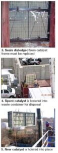
Verifying the integrity of catalyst seals, which can fatigue and fail over time, also is important. They prevent untreated exhaust gas from bypassing the SCR. Check catalyst element sealing within the SCR module, seals between the SCR module and reactor frame, and between the frame and the outside wall (Fig 3). Replace lost seals by adding gasket material. Also consider installation of a retention plate to hold seal packing in place.
Catalyst replacement will be necessary—sooner or later. High ammonia flow or a bad report from the test lab will tell you when the catalyst must be replaced. But it’s important to trend catalyst activity over time and to predict the optimal time for replacement. Reason: A typical SCR order lead time is nine months to a year. Removing spent catalyst and installing new generally can be accomplished for an F-class unit within five two-shift days (Figs 4, 5).
Don’t forget to characterize the spent catalyst to determine its waste characteristics. All spent catalyst is not accepted in all landfills. In some cases, it may be more economical to recycle the catalyst rather than send it to a landfill.
Catalyst regeneration for gas-fired plants may be a viable option in the future, but it’s unlikely it would be economical now judging from McTernan’s comments. He said there’s limited HRSG regeneration experience today, but noted that Cormetech has a partnership with a leading reprocessor of catalyst for coal-fired plants aimed at developing a solution for this market sector.
Catalyst for coal-fired plants gets plugged with ash and contaminated with arsenic and calcium, he said. So for that market, regeneration essentially consists of cleaning and restoration of active catalytic metals by re-impregnation. SCRs at natural-gas-fired plants typically lose performance from a gradual loss of catalytic surface area—a physical change in the microscopic structure of the material that is a permanent loss.
In development, McTernan said, is a regeneration process with the potential to benefit units that have lost performance because of excessive salting or accumulated contaminants requiring a liquid solution for removal. Coated SCR catalysts, he added, may deactivate from loss of the catalytic coating itself. In that case, recoating or full replacement is required, not cleaning.
Looking toward the future, keep in mind that prequalification trials of site samples will be necessary to determine the degree to which a specific regeneration process may be effective. Also, cleaning and catalytic enhancement probably will require offsite processing. These two steps conceivably could require an extended outage, financially penalizing the regeneration option.CCJ