
By Mark A Goodman, UE Systems Inc
One of the main reasons for the advances in condition monitoring programs has been the development and use of technologies such as ultrasound, oil analysis, vibration, and infrared evaluations. This article examines one of these technologies, airborne/structure-borne ultrasound.
Lightweight and portable, ultrasonic translators are often used to inspect a wide variety of equipment. Typical applications include mechanical testing of bearing and gearboxes; electrical testing for corona, tracking, and arcing; and leak detection on pressurized and vacuum systems.
Ultrasound is effective because all operating equipment and most leakage problems produce a broad range of sounds. The high-frequency ultrasonic components of these sounds are extremely short-wave in nature and, therefore, fairly directional. It is relatively easy to detect the source’s exact location by separating the signals from background plant and operating equipment noises.
In addition, as changes occur in mechanical equipment, the sound they make changes. The subtle nature of ultrasound allows these potential warning signals to be detected early, before an actual failure occurs and often before the problem can be detected by vibration or infrared scans.
Ultrasound instruments, often referred to as ultrasonic translators, provide information in three ways:
- Qualitative with the ability to “hear” ultrasounds through a noise-isolating headphone.
- Quantitative via intensity (dB) readings on a meter or display panel.
- Analytical with the use of spectral-analysis software to review recorded sound samples.
Although the ability to gauge intensity and view sonic patterns is important, it is equally important to be able to hear the ultrasounds. That is precisely what makes these instruments so popular. They allow inspectors to confirm a diagnosis, on the spot, by being able to clearly discriminate among various equipment sounds. This is accomplished in most ultrasonic instruments by an electronic process, called heterodyning, that accurately translates the ultrasounds into the audible range, so users can hear and recognize them through headphones.
Ultrasound translators are relatively simple to use. They consist of a basic handheld unit with headphones, a display panel, a sensitivity adjustment, and (most often) interchangeable modules that are used in either a scanning (airborne) mode or a contact (structure-borne) mode. Some instruments have the ability to adjust the frequency response between 20 and 100 kHz. Ultrasound instruments may be analog or digital.
Digital instruments indicate intensities as decibels and generally have onboard data-logging with data management software to provide trending information and to create alarm groups for equipment needing special attention. Some of the digital instruments also have onboard sound recording (either in MP3 format or a tape recording) capabilities, which let a user to grab sound samples and review them with spectral-analysis software.
Applications
Applications for ultrasonic translators fall into three, generic categories: mechanical inspection, leak detection, and electrical inspection.
Mechanical equipment produces a “normal” sound signature, while operating effectively, but a change in the original sonic signature occurs as components begin to fail. This change can be noted as a shift in intensity on a display panel and/or as a qualitative sound change that can be heard through headphones. An ultrasonic translator may be connected to a vibration analyzer or the sound samples may be reviewed through spectral-analysis software on a laptop.
Mechanical: bearings
One valuable application of mechanical inspections is bearing testing. According to NASA, ultrasonic monitoring of bearings provides the earliest warning of bearing failure. The agency notes that an increase in the amplitude of a monitored ultrasonic frequency of 12 dB, over baseline, would indicate the initial (incipient) stages of bearing failure. This change is detected ultrasonically, long before it can be detected by changes in vibration or temperature.
Ultrasound translators can also be used to aid in diagnosis. The high-frequency, short-wave characteristic of ultrasound allows the signal to be isolated, so a user can hear and determine if, in fact, a bearing has been correctly diagnosed as failed.
Ultrasound detectors work well on slow-speed bearings. In some extreme cases, just being able to hear some movement of a bearing through a well-greased casing can provide information about potential failure. The sound might not have enough energy to stimulate classic vibration accelerometers, but will be heard with ultrasonic translators, especially those with frequency tuning.
In addition, most slow-speed bearings take a long time to analyze with typical vibration equipment, but by connecting an ultrasonic translator to the vibration analyzer, the resolution improves and the time to grab a sample drops dramatically.
Mechanical: gearbox
To illustrate how valuable ultrasonic evaluations can be, consider the following case study. A tube manufacturing plant had six gearboxes coupled together. Each was driving tools that bent steel to form tubing. An inspector was collecting data from the gearboxes with an accelerometer for vibration analysis and an Ultraprobe® ultrasonic translator.
When listening to the gearboxes with the Ultraprobe, five made a hissing-type sound, one a ticking sound. A time waveform was captured using the accelerometer and then using the ultrasonic translator for both the questionable gearbox and the one next to it. The waveforms from the accelerometer are shown in Figs 1 and 2.
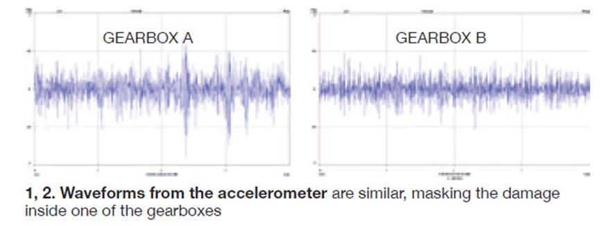
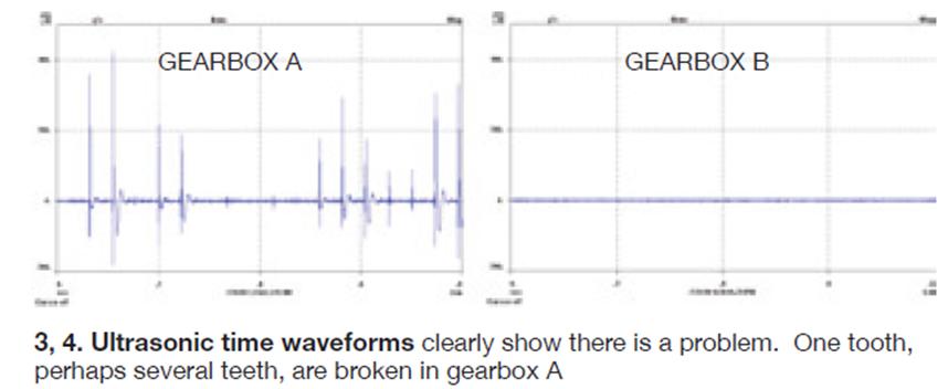
By comparing the two time waveforms, you can see that there is a slight difference between the two gearboxes. When you look at the ultrasonic waveforms, the problem becomes more defined, indicating that there is a broken tooth (or teeth) in gearbox A (Figs 3 and 4).
An evaluation can also be done with spectral-analysis software. A similar type of Fast Fourier Transform (FFT) diagnosis can be performed on a standard PC, as long as it has a sound card.
These programs not only provide the spectral and time-series views of sound, but also enable users to hear the sound samples simultaneously, as they are viewing them on the PC monitor. Some ultrasonic instruments make on-board sound recordings, which can then be downloaded to a PC via a compact flash card. When played back in real-time, the acoustic properties can be analyzed and, based on a known-good or normal condition, an anomaly can be quickly identified.
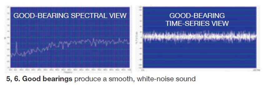
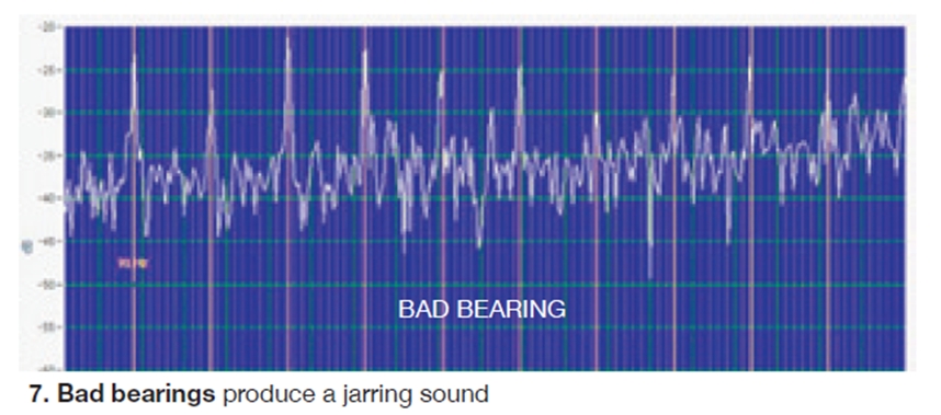
Figs 5 and 6 show the spectral and time-series views of a good bearing. If one were to imagine the sound a good, lubricated bearing makes, it would be a smooth, rushing sound. Note that there are no distinguishing characteristics: This is an example of white-noise. Now, consider a bad bearing (Fig 7). Notice the shift. The bearing is producing a jarring, buzzing noise. Note the fault frequency has been captured as 90-Hz harmonics.
 The advantage of ultrasound inspection, aside from providing a finer resolution for viewing the sound image, is that inspections can go beyond what is possible to do with typical vibration or infrared scans.
Mechanical: compressor valves
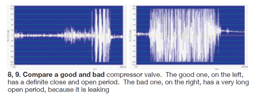
Ultrasonic evaluations can be very useful for testing valves. For example, reciprocating compressor valves are very noisy and produce a lot of extraneous vibration. By isolating the sound, with the advantage of the short-wave nature of ultrasound, it is possible to listen to and view the sounds of these noisy valves in real-time and to identify a leaking valve.
As a good compressor valve opens and closes, there will be a definite, pronounced clicking. Shown in Fig 8, a good valve will have a definite closed period followed by a distinct open period. A bad valve (Fig 9) has a very long open period because it is leaking. If one listens to these samples, the difference is very obvious.
Mechanical: lubrication
In some facilities, equipment is lubricated on a fixed, time-based schedule. Other facilities rely on more effective and efficient predictive models. With routine ultrasonic testing, lubrication technicians can be taught how to effectively apply just enough lubricant to do the job and without over-lubricating.
In general, when a bearing has exceeded its baseline by 8 dB, with no change in acoustic quality, the bearing should be lubricated. While applying lubrication, the technician should stop when the sound level has dropped to the pre-determined baseline level.
A way to demonstrate this process is to view a sound image, while noting changes in amplitude and listening to acoustic properties in real time. Fig 10 illustrates a sample spectral view of the sound recorded, while a bearing was being lubricated. The top, red overlay is the non-lubricated state. Note how the sound level drops as the lubricant is applied.
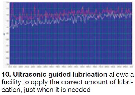
When the proper lubrication level is reached, the sound level drops by 8 dB with no change in sound quality. There are no distinctive harmonics or spikes, only a representation of the white- noise you would expect to hear, if you were to listen as this sound sample played.
Electrical: corona, tracking, arcing
Now consider the ultrasonic characteristics of electrical emissions. One thing to watch for is the presence of harmonics. Some preliminary experimentation has shown that the main harmonic component of electrical emissions will be most prevalent in corona. As the problem becomes more severe, fewer and fewer 60-Hz harmonics will be observed. Tracking has few 60-Hz components and arcing has very few.
So, when possible, listen to the sound characteristics as they are played in the spectral view and note that the harmonics of 60 Hz diminish as the condition becomes more severe. The frequency content will move up and down in relation to the ionization produced by the particular emission (corona, tracking, or arcing).
| Corona | Tracking | Arcing |
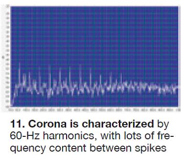
Fig 11 is a view of corona. Note the steady display of 60-Hz harmonics with a lot of frequency content between the spikes. If one listens to corona, it has a distinct buzzing and crackling noise.
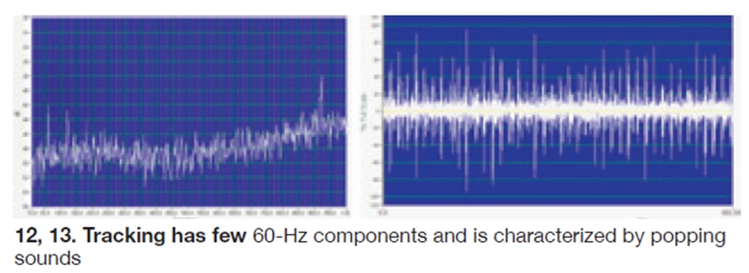
Figs 12 and 13 show tracking. Sometimes referred to as “destructive corona,” tracking has a different acoustic property. This type of emission has a rapid build-up and discharge called “baby-arcing.” Note that the 60-Hz harmonics have diminished.
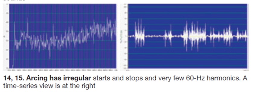
Arcing is shown in Fig 14; a time-series view is in Fig 15. Note that it has irregular starts and stops and very few 60-Hz harmonics. Arcing primarily contains violent starts and stops.
Leak detection
The category of leak detection covers a wide area of plant operations. Some plants include it as part of an energy conservation program, while others use it to reduce fugitive emissions. No matter what it is called, leaks cost money, effect product quality, and wreak havoc on the environment.
Leaks can occur in liquid or gas systems. The greatest advantage of ultrasonic detection is that it can be used in a variety of leak situations, since it is sound sensitive—not gas specific. Therefore, it can be used to find pressure leaks (compressed air), negative pressure leaks (vacuum), and leaks in valves and steam traps.
When a liquid or gas leaks, it moves from the high-pressure side of a leak, through the leak site, to the low-pressure side. Once there, it expands rapidly and produces a turbulent flow, which has a strong ultrasonic component. The ultrasonic intensity of the signal falls off rapidly the further the test equipment gets from the source. For this reason, the exact spot of a leak can be located.
Wrap-up
Airborne ultrasound instruments are becoming an important part of condition monitoring, fugitive emissions and energy conservation programs. Their versatility, ease of use and portability let managers effectively plan and implement inspection procedures. By locating leaks, detecting high-voltage electrical emissions, and sensing the early warning signs of mechanical failure, these instruments help reduce costs, improve system efficiencies, and reduce downtime. For optimum effectiveness, it is recommended that all major technologies, infrared, vibration and ultrasound, be used as part of a comprehensive inspection program. CCJ