
Checklist facilitates troubleshooting
Shawn Burdge of Turbine Technics Inc, a familiar face at user-group meetings, shared his knowledge on ignition-system troubleshooting with owner/operators attending the 7EA Users Group conference last fall. The information disseminated is of value to a much broader community of users and is summarized below so others may benefit from it.
Burdge began his presentation by saying troubleshooting will reveal only that a malfunction has occurred in one of the three primary components of your ignition system: the exciter, ignition lead, or igniter plug.
The ignition exciter cannot be repaired. If defective, it must be discarded and replaced. A careful visual inspection will identify any problems. Here’s what you should do:
• Examine the cover and housing for cracks, dents, or other damage. Cracks are not permitted; small dents can be removed if no cracking is in evidence.
• Check the exciter’s output terminals and posts for signs of burn marks caused by electrical arcing or flashover. Also look for cracks or other damage to the posts, and for
damage to the terminal threads.
• The potting compound also must not have cracks or areas of different color (caused by too much heat). Plus, there must be no space between the compound and housing wall.
• Finally, make sure the exciter is mounted with the drain tube in a vertical position.
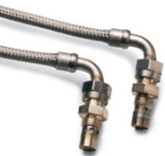
Ignition leads cannot be repaired in the field. However, if a lead malfunctions or incurs damage, it can be sent to Unison Industries for analysis and/or repair. (Turbine Technics Inc is a worldwide distributor of engine components and services offered by Unison Industries LLC.) Both visual and electrical inspections are recommended for ignition leads. Visually, inspect for the following:
• Cuts, worn, or damaged areas on the braid of the outer conduit.
• Worn or stripped threads on the coupling nuts (igniter end).
• Cracks or damage on the brazed fittings at each end of the lead.
• Missing pieces, cracks, or other damage in the ceramic insulator (igniter end).
• Rust, pitting, and/or corrosion of the springs (igniter end).
• Wear or damage that prevents seal washers on the igniter end of the lead from performing their intended function.
• Burn marks caused by electrical arcing or flashover where the lead connects to the exciter and igniter plug.
Inspect ignition leads electrically in the following manner:
• Remove the ignition lead from the exciter and igniter plug.
• Use a standard multimeter (ohmmeter) to measure continuity of the center electrical cable. Measure the resistance between the terminals at each end of the cable. It should be approximately 1 ohm.
• Use a standard megohmmeter to measure insulation resistance between the outer electrical cable and the outer metal braid. Connect the megohmmeter between one terminal of the center electrical cable and the outer metal braid, then apply 500 V dc for a minimum of 30 seconds. The resistance must be at least 100 megohms.
Ignition plug. At the input-terminal end, check the following visually:
• Ceramic insulator, for cracks, missing pieces, looseness, carbon tracks, or contamination—none of which is allowed.
• Contact button, for signs of burn marks caused by electrical arcing, or of considerable wear.
• Threads, for cross-threading or damage. All threads must be serviceable.
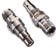
At the firing end:
• Hold the plug and shake it forcefully. A rattling sound indicates loose or broken parts and the plug should be discarded.
• Check the ceramic insulator for cracks, missing pieces, and looseness. None are allowed.
• Look for worn areas, cracks, or holes in the outer area of the shell. CCJ