
Servo valves were developed to precisely control the pressure of oil flowing to hydraulic actuators responsible for transmitting force or torque to open, shut, and/or modulate valves and other equipment. Before servos, human or mechanical means were used to perform such control functions, but they lacked repeatability and flexibility.
In gas-turbine-based powerplants, servos control fuel flow, combustor bypass, compressor bleed valves, NOx control water (or steam), as well as the position of inlet guide vanes and of critical valves on steam turbines in combined-cycle plants. This means they are important to your plant’s performance and safe operation and demand respect despite their small size and seemingly pedestrian function.
Many servo valves operate reliably for five years or more, while the performance of others is compromised by sticking and wear of critical parts. The extremely close tolerances between moving parts—and for critical orifices— that are required for precise control, demand pristine hydraulic fluid and regulation of oil temperature within manufacturer limits.
Design/operation. The oft used nozzle/flapper type of servo has two main parts, Gary Morrison of United Servo Hydraulics Inc, Waynesboro, Va, told the 501D5/D5A Users at their annual meeting last June: a torque motor and a bushing/spool assembly (Fig 1).

Valve works this way: An electrical input signal induces a magnetic charge in the armature and causes a deflection of the armature and flapper. This assembly pivots about the flexure sleeve and restricts fluid flow through one of the two nozzles shown in the diagram.
Assume that the right side of the flapper moves closer to the right nozzle, thereby creating higher pressure in the right passage and lower pressure in the left passage. The higher pressure in the right passage acts on the right end of the spool, applying force ing to displace the spool to the left. At the same time, lower pressure is acting on the left side of the spool, creating a force imbalance and facilitating the spool’s movement to the left. As the spool moves, the supply pressure port on the left opens to the adjacent control port and the return port opens to the control port on the right.
Spool motion is transmitted to the ball end of the feedback spring, creating a restoring torque on the armature/ f lapper assembly. Once the restoring torque becomes equal to the torque created by the magnetic forces, the armature/flapper assembly moves back to the neutral position and spool movement stops (fluid pressure on both sides of the spool are in balance)—that is, until the input signal changes.
Two things to take away from the foregoing:
1. Spool position is proportional to the input current and, with constant pressure drop across the valve, flow to the load end of the servo is proportional to spool position.
2. Nozzle openings must be “as new” and nozzle/flapper spacing precise to assure proper servo response. Also, sharp metering edges on the bushing/spool assembly are critical for accurate flow.
 How to maximize servo life, availability
- Closely monitor hydraulic oil; send samples for analysis monthly.
- Monitor and regulate oil temperature at the reservoir. Keep in mind that oil in the servo valves generally is hotter than that in the reservoir because the ambient temperature at the servo location is higher and heat is generated by the friction of oil being forced at high pressure through nozzles. Contaminants present in the oil increase friction and increase the amount of heat produced.
- Recondition all servos at the first available outage to provide a baseline for monitoring and tracking system performance. Plan on reconditioning valves at intervals of 18 to 24 months— including parts cleaning, new Viton seals, parts inspection, parts replacement where needed, new filter, and functional testing.
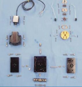
- Stock spares of each component in the plant warehouse (photo).
Wear and tear. Morrison, whose firm services and rebuilds hundreds of servos annually, told the 501D5/D5A Users that the company finds varying degrees of damage to these critical valves. Causes of wear and general deterioration include heat, vibration, fluid contamination, electrical erosion, and acid formation in phosphate ester-based hydraulic fluids.
Generally, he said, when heat, contamination, and acid content are controlled to levels less than those specified by the manufacturer, servos show little wear, even over a period of years. Typically, all technicians will find during normal servicing are some contaminants deposited on the filter media (Fig 2) and bushing/ spool assembly.
However, excessive heat and contamination can cause the valve to stick or freeze. Plus, particle bombardment can cause pitting of the bushing/spool and nozzle/flapper assemblies. Large contaminants and/or collections of small particles (so-called silt) can plug the servo filter, nozzles, and orifices. This restricts the control flow through the torque motor, limiting spool end pressure, and causing loss of valve control.
In valves that have been attacked by acid formed in improperly maintained phosphate ester-based fluids, service technicians find erosion of critical metering edges and nozzles. Such damage, which can occur within a few months or less, causes excessive internal leakage and adversely impacts servo response time.
Other wear points that impact servo performance include flapper (Fig 3) and nozzle erosion and wear (Fig 4), and flattening of the ball at the bottom of the feedback spring (Fig 5).

Keeping oil clean. Morrison said that more than three quarters of all servo problems are a direct result of fluid contamination. He added that a high concentration of contaminants forced at high pressure through nozzles increases oil temperature in the valve above that in the sump. Heat is the enemy, Morrison continued, because it contributes to varnishing, which impedes the movement of servo parts.
Removal of particulates can be accomplished with return-line filtration or an off-line filter system. If you are having difficult keeping contaminants out of your hydraulic oil, consider upgrading the filtration system. Remember that this is your first line of defense against valve problems.
Servos are equipped “last-chance” filters, which typically are made of wire mesh and built into the body of the valve in the pilot-stage supply line. Do not rely on this filter to clean your hydraulic oil system; its purpose is to protect internal valve parts in case the primary filtration system fails. Loss of valve response is one symptom of excessive contaminant loading in the servo filter. Others include jerky motion and high null bias—that is, a high input current is required to maintain the hydraulic cylinder operated by the servo stationary. If irregular operation requires frequent replacement of the servo filter, check for problems with your system filter.
An interesting fact presented by Morrison was that the small filter incorporated into a typical servo installed on a large frame machine may process 100,000 gal/yr of oil. Thus, even a low concentration of contaminants can adversely impact valve operation.
Predictive maintenance. Savvy plant managers know that a prerequisite for completing an outage on time and within budget involves careful planning of all the work required. Valuable information on the condition of servos can be gathered by diagnostic testing in advance of planning meetings. Outside services available to plants include:
- Non-intrusive flow measurement, to periodically measure the internal leakage of individual components in an operating hydraulic system. Variations over time may indicate normal wear, fluid contamination, or damaged seals.
- Component isolation testing, to isolate bad parts in an otherwise healthy system. Pump cycle times, excessive amp draw, and pressure losses can indicate a failure in a hydraulic system.
- Periodic sampling and testing of hydraulic oil by an experienced laboratory.
Plant staff, if properly trained and equipped, can do some or all of the foregoing diagnostic work. Handheld test instruments—at least one for under $500—are available to verify proper valve operation prior to startup, check null bias, etc. CCJ OH
Servo maintenance checklist
United Servo’s Gary Morrison shared with the 501D5/ D5A Users the company’s maintenance recommendations for hydraulic systems. By following this six-step program, plant personnel can avoid many nagging problems that have been experienced with servos.
1. Fluid maintenance
- Replace filters regularly with OEM parts or equivalent.
- Plants using Fyrquel hydraulic oil: Consider a filter offering control of moisture and acid.
- Keep reservoirs filled to recommended levels to avoid condensation, a major source of problems.
- Consider an offline filtration system or kidney loop for high-contaminant situations.
- Test and flush at manufacturer-suggested intervals. Be sure to recondition or flush servos and cylinders, especially if using a flushing block.
2. Actuators (cylinders)
- Recondition and rebuild often.
- Check alignment to prevent seal breakdown and scoring.
- Keep tools off the rod.
- If you rebuild in-house, bevel edges and test on stand at high pressure prior to recommissioning.
3. Control heat
- Check for sources of heat.
- Maintain oil temperature in the sump below that suggested by the manufacturer.
- Clean heat exchanger and reservoir walls during outages.
4. Servos and other valves
- Clean and calibrate every 18 to 24 months; more often if necessary.
- Over clean; avoid repairs that require parts replacement.
- Handle servos with care. No hammers. Do not disassemble.
5. Consolidate system services with one vendor
- Maintain cylinders, servos, pumps, filters, and motors to a consistent standard.
- Have vendor develop a records database detailing services, costs, serial numbers, type of repair, etc.
6. Spares
- Maintain a full set of servos if your outages typically are short; a partial set if outages are long enough to order replacements without impacting the critical path.
- Keep spare cylinders in the warehouse—full set or partial.
- Buy in bulk if possible.