Extracting maximum value from generation assets
 Larry Small, chairman of the Combined Cycle Users Group, reports that planning is well along for the CCUG’s 2013 Annual Conference, to be held in Phoenix at the Arizona Biltmore, September 3 – 5 (see adjacent sidebar). Presentations and discussion sessions will focus on topics of critical importance to owner/operators of combined-cycle plants, he said. For program details, access the organization’s website at www.ccusers.org.
Small also announced two programs launched by the CCUG in conjunction with the COMBINED CYCLE Journal—one to recognize plants that exceed general industry performance expectations, the other to recognize individual achievement. Read more about each on pages 109 and 111, respectively. Finally, the chairman urged users to register as a CCUG member (no charge) at ccug.users-groups.com to participate in the group’s online forum.
Small, who is director of engineering in Calpine Corp’s Engineering & Construction Dept, injected a dose of adrenaline into the opening session on reliability and strategic planning at the 2012 meeting, getting last year’s conference off to a fast start. It was held October 16 – 18 at the Orlando area’s Buena Vista Palace hotel. Prepared presentations and open discussion provided a snapshot of cycle and equipment design improvements to improve availability/reliability/performance, emerging technologies for fast start/ fast ramp, and the challenges associated with integrating renewables and conventional generation.
The renewables challenge
Steve Royall, director of fossil and solar generation for PG&E, and a member of the CCUG Steering Committee, spoke about the demands imposed on conventional generation assets by California’s requirement that one-third of the state’s kilowatt-hours come from renewables in 2020.
The load profile projected by the California Independent System Operator (CalISO) for January 2020 illustrates the challenge well (Fig 1). Note the (1) rapid ramp in conventional generation required in the early morning (8000-MW increase within two hours); (2) the 6300-MW mid-morning decrease as demand levels off and solar generation increases rapidly, and (3) the 13,500-MW ramp in conventional generation required within two hours as the work day comes to an end.
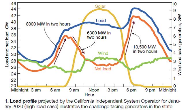
The chart suggests that at least some combined-cycle plants might be forced to start twice daily to satisfy California’s requirements. Wear and tear on equipment is only one concern. One attendee asked: “What about the increase in total annual emissions because of the greater number of starts? Will permits be relaxed?” The reply: Still too early to have all the answers. Group think suggested that “operational flexibility” might be an ancillary service in the future because generators must be compensated for withdrawals from their metal-fatigue bank accounts.
More peakers is not necessarily a viable strategy, the 70 attendees concluded. The efficiency of a simple-cycle engine is lower than that of a combined cycle, which contributes to higher emissions.
Royall also shared some details on PG&E’s aggressive solar PV program, put in place to comply with the state’s renewables statute. In both 2011 and 2012, the company commissioned three facilities totaling 50 MW; three more solar plants with a combined capability of 50 MW are scheduled for service by the middle of this year.
PG&E plans to install a total of 250 MW of photovoltaic capacity before 2016 and contract for another 250 MW as well. The owned PV infrastructure is expected to cost about $1.5 billion. The price the utility receives its solar power is capped at $246/MWh. The solar generation it purchases competitively may not exceed $246/MWh.
Some facts of interest include the following:
-
The stationary PV panels installed by PG&E have a guaranteed life of at least 25 years, and an average annual degradation rate of less than 1%.
-
PV panels generate electricity best under bright sunshine when the ambient temperature is cool. The spring and autumn months are best for solar generation.
-
Solar PV sites require from six to 10 acres per megawatt.
Fast start, fast ramp
Given the demands being placed on generators by grid operators in a regulatory world requiring ever lower emissions of CO, NOx, and CO2, it’s apparent that most assets on the ground are not optimum. The gas-turbine OEMs have responded with new lines of fast-start/fast-ramp combined cycles powered, in some cases, by the largest and most advanced frame engines available. The vendor offerings look good on paper, of course, but there is virtually no operating experience to date to support at least some claims.
Concerned about flagging orders for new generation, vendors are stoking a fast-start buzz that may at least be capturing the hearts and minds of public officials—if their turnout at the dedication last summer for Northern California Power Agency’s Lodi Energy Center is any indication.
Lodi is considered by industry observers as the nation’s first generating station designed specifically for fast starting. The nominal 300-MW 1 × 1 facility, a Siemens Flex-Plant™ 30 equipped with an SGT6-5000F gas turbine, is designed to deliver approximately 200 MW within 30 minutes of pushing the start button. It is said to be capable of daily cycling at efficiencies of over 57%.
Getting the electric-power industry to embrace “flexible” generation is critical to the financial success of OEMs. Reason: They likely would provide major equipment for the entire plant—gas and steam turbines, generators, and heat-recovery steam generators (at least in the cases of Alstom, Mitsubishi, and Siemens, which recently purchased NEM). Otherwise, it might be difficult to hold an OEM accountable for plant performance.
If generation executives are sold on the value proposition of integrated fast-start/fast-ramp plants, it could mean lean days ahead in the US market both for steam-turbine suppliers that do not also offer large gas turbines and for some HRSG manufacturers. Plus, it could put investments in grey-market equipment at risk; and expanded long-term parts/services agreements likely to be part of any flexible-plant sale would reduce the opportunities for third-party services providers.
Startup times for plants like Lodi are reduced by up to 50% compared to conventional combined cycles. Fast-start enabling technologies include a triple-pressure HRSG that incorporates Benson® once-through technology in the HP section, high-capacity steam attemperation, and 100% steam bypass systems. Other features that facilitate fast starts: an innovative solution for warming high-energy piping systems, Siemens’ steam-turbine stress controller, and a standby auxiliary steam system to maintain vacuum.
Siemens Energy Inc is the leader in fast-start plant orders—at least based on public announcements received by the editors. Projects in the planning and construction stages include the following:
-
A 1 × 1 Flex-Plant 10 at NRG Energy Inc’s El Segundo (Calif) Energy Center, scheduled for operation in August 2013. The new plant will burn 30% less natural gas than the units it is replacing. Air cooling enables the facility to shutter its once-through ocean-water cooling system in compliance with California rules.
-
Panda Temple Power LLC recently signed contracts with Siemens for two nominal 600-MW, 2 × 1 Flex- Plant 30 combined cycles on one site in Temple, Tex. The four SGT6- 5000F gas turbines will have the OEM’s Shaping Power ™ feature to enable increased power production on hot days.
The first facility is expected in commercial operation by the end of 2014; equipment purchasing and construction preparations are underway. The order for two Benson-type HRSGs was awarded at the end of July to NEM USA, Greenville, SC. Bechtel Corp was selected as the EPC contractor and is responsible for balance-of-plant equipment.
GE Power & Water’s first fast-start combined cycle in the US apparently is several years away. Developer Radback Energy Inc received permission from the California Energy Commission in May 2012 to begin construction of the 624-MW Oakley Generating Station (formerly called Contra Costa). It is expected in service by summer 2016. Published reports say PG&E plans to buy Oakley if it meets operational expectations.
 Siemens’ success prompted an invitation from Chairman Small to participate in the Reliability and Strategic Planning Session. Jacki Engel, marketing manager for the company’s 60-Hz product line brought attendees up to date on Siemens’ fast-start offerings. Flex-Plants, she said, are the result of an evolutionary process to create fast, reliable combined cycles that fully leverage the gas turbine’s operational flexibility—specifically, fast start, rapid response to load changes, and dependable shut down and restart.
To illustrate: A nominal 600-MW 2 × 1 Flex-Plant 30 can deliver 300 MW 10 minutes after starting and achieve rated output with steam-turbine valves wide open in less than an hour— provided it has not been offline for more than about 16 hours.
The Siemens 60-Hz Flex-Plant portfolio incorporates eight offerings with ratings from 170 to more than 1200 MW. At the low end is a 1 × 1 configuration incorporating a V84.2 engine. The balance of the product line includes 1 × 1, 2 × 1, and 3 ×1 arrangements of F- and H-class machines.
All of these high-efficiency options are said to cycle on and off and ramp up and down like a simple-cycle engine. Example: A 2 × 1 F-class plant can increase and decrease load at rates of up to 75 MW/min. The portfolio’s Clean-Ramp™ feature is said to keep stack emissions in compliance with the permit while load following up to the full ramp rate.
Retrofit solutions. Even if California Governor Jerry Brown were convinced that fast-start combined cycles are the preferred solution for meeting his state’s demanding renewables portfolio standard, don’t expect generation executives to scrap their existing plants and buy new ones. Rather, many have begun to evaluate retrofit and upgrade alternatives that would allow their plants to provide grid services conducive to a strong balance sheet.
Understanding what owners should consider to keep existing plants competitive was one of Chairman Small’s objectives for the keynote session. Many in the industry believe that gas turbines purchased since the bubble, as well as some bought toward the end of that buying frenzy, can handle fast starts and ramps. They also agree that the Rankine cycle is where the real challenges are.
The positive feeling about the gas turbine’s operating flexibility was echoed by two participants in the Industry Issues Roundtable hosted by the Combustion Turbine Operations Technical Forum’s 37th Annual Fall Turbine Users Conference in mid-September. The CalISO’s David Timson said he believed that gas turbines installed in the last 10 years generally would not have a problem meeting the grid’s “flexibility” objectives. A clear message he delivered to attendees regarding existing generation that does not now meet the ISO’s goals: “retrofit, repower, or retire.”
Another panelist, Bruce Rising of Siemens, a GT expert, told CTOTF attendees that fast-start engines were developed before renewables integration achieved headline status. He said that the OEMs were sensitive to the need for generators to get their units into service with minimum emissions and fast starts were critical to that goal.
A caution flag went up from the insurance industry’s participant in the discussion, Marsh Senior VP Donald Schubert. He said that insurers generally are not enamored of fast starts when they involve “older” combined-cycle plants. “Old” in the insurers’ lexicon, Schubert continued, is five or six years.
HRSGs have limits
 The fast-start challenges on the steam side of the plant are obvious to most experienced designers and operators of Rankine cycle equipment. HRSGs, attemperation systems, main-steam and reheat piping, startup drain systems, SCRs, steam seals and vacuum systems, and condensers and their steam dump systems require careful engineering evaluation, and upgrades in some cases, to accommodate the more severe duty. The boilers, in particular, are sensitive to fast starts and ramps.
Small invited HRST Inc’s Bryan Craig, PE, to discuss possible boiler design constraints that could adversely impact a given unit’s ability to start and/or ramp quickly. Craig began with a review of NFPA purge requirements.
He reminded the group that the HRSG must be purged of combustible gases before the GT is fired. This translates to five changes in the gas-side volume extending from the engine to the point where the turbine exhaust temperature is 100 deg F below the auto-ignition temperature (typically the far end of the HP evaporator).
The engineer said that HRSG design details often are unknown when the purge time is needed by the engine OEM, and a default number is programmed into the control system. For GE 7FAs, the default purge time typically is 15 minutes when only 7 to 9 minutes generally is necessary. A few hours of engineering effort is all that’s generally required to calculate the purge requirements for a given unit and make the necessary control-system adjustments.
You can save even more time on a startup if your gas turbine is equipped to burn only natural gas and the HRSG is not capable of supplementary firing. By purging on shutdown rather than at startup, the time required for your next start can be reduced by as much as 15 minutes.
An engineering evaluation of drum-level controls was recommended by Craig. Recall that the rapid increase in steam production during a fast ramp causes drum-level swell. If carryover occurs, a unit trip is possible. IP drums are particularly susceptible to carryover because of their relatively small size.
For fast-start units, Craig recommended the use of three-element control with a moving set point, and minimum flow through the feedwater control valve, to help automatically manage swell while maintaining economizer flow with minimal operator intervention. He suggested that users not shy from using intermittent blowdown to reduce drum water inventory when necessary.
Fuel-gas heater permissives were next on Craig’s list. He reminded: Some gas-turbine OEMs require fuel-gas heating to meet NOx guarantees and assure emissions compliance. Water from the IP economizer outlet typically is used as the heat source for this purpose. Permission to increase load is obtained once fuel gas is 300F.
But, in some piping schemes, the IP drum pressure must exceed the condensate discharge pressure (275 to 325 psig) before water can flow through the performance heater. In those instances, moving the feedwater control valve from upstream of the IP economizer to downstream of it will allow water flow through the heater and enable startup to proceed faster.
However, this requires the IP economizer to operate at a higher pressure than what it was designed for. An engineering study is necessary. If the location of the feedwater control valve can be changed without replacing pressure parts, recertification of the economizer is required by the ASME Boiler & Pressure Vessel Code.
Steam-turbine temperature matching is another possible issue. The startup time for the gas turbine may have to be extended if the steam temperature leaving the HRSG exceeds steam-turbine warm-up requirements. In many instances, the desuperheater cannot provide the level of temperature control required and a GT hold is necessary.
Ways to minimize the probability of a mismatch, Craig said, include the use of electric blankets to heat the steam turbine prior to startup and/or installation of an air attemperation system to control steam temperature independently of GT load.
The HP drum can suffer fatigue damage when pressure changes quickly because of the resulting temperature gradient across the vessel wall. Specifically, the inside of the drum quickly tracks changes in saturation temperature while the outside wall requires “soak” time to come to the new temperature. If the temperature differential is too great, the resulting stresses can initiate cracks at discontinuities such as large nozzles.
Craig said HP drum nozzle cracks are surprisingly common in HRSGs that cycle and that weld design is a contributing factor. It is possible to mitigate cracking by grinding out existing partial-penetration nozzle welds and replacing them with full-penetration welds of either the pass-through or set-on type. However, this work is difficult, expensive, and time-consuming.
There are several ways to protect steam drums against harmful thermal stresses. One is installation of a monitoring system that alarms on high drum stress based on measured temperature differentials, enabling you to slow-down the startup process or ramp rate. Another is a steam sparging system to keep the drum warm and pressurized while the unit is offline, thereby reducing the temperature differential that accompanies a startup.
Another corrective action is to control the HP-drum pressure ramp independently of the GT startup rate. But to accomplish this you need somewhere for the steam to go. A full bypass system that routes superheater outlet steam via the cold-reheat line, reheater, and hot-reheat line to the condenser is one approach. Another is to use sky vents. One negative associated with the latter is the loss of costly demineralized water.
Get more from your GT with an engine
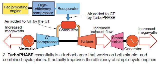
The discussion on emerging technologies for fast start/fast ramp during the Reliability and Strategic Planning Session was the perfect segue for Bob Kraft, founder/CEO of PowerPHASE LLC, to introduce to the CCJ editors, during the ensuing coffee break, the company’s latest product—TurboPHASE™.
He said it can boost the output of a combined-cycle plant by up to 15%, and a simple-cycle gas turbine by up to 20%. This is achieved by addition of a skid-mounted assembly, consisting of an efficient reciprocating natural-gas or diesel engine and an intercooled compressor, which injects hot high-pressure air directly into the combustion section of the GT, thereby increasing mass flow through the turbine (Fig 2).
The additional power is available within a minute or so of starting the auxiliary engine, the former PSM founder and president said. For a 7FA.04-equipped 2 × 1 combined cycle, a 5% TurboPHASE injection into each gas turbine means more than 40 MW is available (18 MW from each GT, plus 5 MW from the steamer) almost instantly. It can be used to (1) compensate for the sharp drop in power output experienced by some intermittent renewable resources during sudden changes in weather, and/or (2) provide a dispatchable source of peaking power.
The amount of air injected into a given gas turbine is determined by an engineering study that considers specific limits of plant equipment—such as the GT, generator, transformer—as well as the ambient range for which the extra power is desired. Typically, the equivalent of from 5% to 10% of compressor inlet air can be added in the combustion section.
TurboPHASE evolved from the company’s work aimed at developing efficient, grid-scale modular compressed-air storage packages that Kraft believes will have international application where and when energy storage is better appreciated. But the value of the system to generating companies today goes well beyond its inherent ability to back up intermittent renewables and to enhance the value of existing gas turbines for peaking duty.
Specifically, it is a less costly and more efficient alternative than steam injection and air inlet chillers for increasing combined-cycle output and performance on hot days. Kraft said that the use of steam injection and inlet chilling can match the GT power boost of his “turbocharger” but those alternatives reduce steamer output and increase parasitic power consumption, penalizing both total output and heat rate.
TurboPHASE has no effect on base-load combined-cycle efficiency, running or not. The heat rate of the TurboPHASE incremental power on such a unit is substantially better than any simple-cycle gas turbine available—and it actually improves the efficiency of simple-cycle engines.
When asked about other options for quickly boosting output, Kraft shared his thinking on fogging and duct burners. Fogging, he admitted, was an efficient way to increase power, but the experienced jet-engine designer said the amount of additional output is limited. Likewise, duct burners can add peak power but there’s an efficiency penalty.
Regarding emissions, the engine can be equipped with an SCR and an oxidation catalyst to hold NOx and CO emissions, respectively, within permit limits. Alternatively, the recip’s exhaust can be injected into the GT exhaust stream to use emissions control solutions provided with the gas turbine.
High-energy piping
Harry Eisenbise, a senior mechanical engineer for WorleyParsons, brought attendees up to date on materials qualified for high-energy piping systems. Owner/operators still reeling from P91 issues appeared to breathe a sigh of relief when they learned that P92, one option for main-steam and hot-reheat systems, does not yet have widespread support in the US.
High-energy fluid systems get regular in-depth coverage at CCUG meetings, the only user group to do so. In 2011, Dr David Buzza, a senior engineer (metallurgist) for AEP walked owner/operators through P91 piping fabrication guidelines, stressing verification of as-received material quality and the importance of post-weld heat treatment (PWHT). In the same session, Jonathan McFarlen of M&M Engineering Associates showed users how to conduct a meaningful assessment of their high-energy piping systems. Access presentations from 2011 and 2012 at www.ccusers.org.
 Eisenbise said the materials of choice today for main-steam and hot-reheat piping were P91 and P92 seamless alloy steel. Seamless and welded carbon steel (Grades B and C), and seamless and welded P11 alloy steel, are the options for cold-reheat and extraction-steam piping, with P22 an additional choice for the latter. Seamless carbon steel (Grades B and C) also is specified for feedwater discharge piping. Materials choices for the auxiliary steam system are seamless carbon steel (Grade B) and seamless P91 and P22 alloy steel pipe.
Next, the senior engineer reviewed the properties and status of the two most sophisticated materials for high-pressure/high-temperature powerplant applications. P91, a modified 9% chromium/1% molybdenum alloy steel, was developed in the US more than 30 years ago and is qualified for use in both new and retrofit piping-system applications.
P92, which most attendees were not familiar with, is a modification of P91. It contains 1.5% to 2% tungsten and typically has only one-third to one-half of the molybdenum used in P91. P92 was designed primarily for piping systems in advanced supercritical coal-fired plants and is viewed as a major improvement on P91, Eisenbise said, with a rupture-strength advantage (allowable stress values) of approximately 16% to 30% over the older material at operating temperature.
Both P91 and P92 are known as creep-strength-enhanced ferritic steels. They differ from the P11 and P22 materials most familiar to powerplant personnel in that their properties derive from a specific condition of microstructure, rather than from the chemical constituents of the materials. The downside of this is that manufacturing and fabrication processes must be controlled very carefully to ensure that the appropriate microstructure is achieved, failing which the material will suffer a significant reduction in its creep-strength properties. AEP’s Buzza focused on this in 2011.
Eisenbise then put up a slide listing the following as the advantages of both P91 and P92:
-
High creep-rupture strength (allowable stress).
-
Excellent toughness.
-
Lighter weight because of significant wall-thickness reductions compared to P22. Example: For an 18-in.-OD main steam pipe with design conditions of 4025 psig/1065F, P22 would require a 4.5 in. wall, P91 only 2.5 in.—in round numbers.
-
Higher temperatures.
-
More flexible piping system.
-
Lower support weight.
-
Lower loads at terminal points.
Disadvantages of P91 and P92 compared to P22 are these:
-
Higher cost of pipe, fittings, and valves.
-
Unforgiving material if proper processing steps are omitted or missed.
-
Longer lead times for processing during fabrication and erection, and heat treatment both for bends and welds.
-
Weld filler material more expensive and less available.
Comparing P91 to P92, the cost of piping, fittings, and valves is higher for the latter; plus the newer material has no meaningful operating history in the US. Regarding prices, Eisenbise said the cost last fall for P91 was between about $3.17 and $368 per pound; P92 was approximately $4.10/lb.
P92 US experience in main-steam and hot-reheat systems is limited to Unit 4 at Wisconsin Public Service’s Weston Power Plant where P92 main-steam piping has been in commercial service since June 2008. The John W Turk Jr Power Plant, in the final stages of construction by AEP subsidiary Swepco, has a P92 main-steam system with a design temperature of 1115F. Offshore, experience with P92 is growing in Europe, Japan, and China. Field reports indicate that some users have expressed concern about cracking of welds and “soft areas” in the piping. Sound familiar?
Lead times for P91 and P92, as well as for carbon steel, are relatively short today compared to only a few years ago, the speaker noted. Suppliers can have P91 pipe at fabricators’ shops in four to five months after order placement. Adding four months for fabrication means pipe can be on the job site ready for installation in eight to nine months following receipt of a purchase order—or in one-third the time it would have taken in 2009.
Eisenbise devoted a considerable portion of his podium time to welding. Here are the key points he made:
Weld filler metal.
Specify in your purchase order that actual—not typical—test reports be provided with all consumables.
-
For P91 and P92, incorporate the following in your specifications:
-
Nickel plus manganese content of the filler metal not exceed 1.5%. These constituents affect the lower critical temperature of the filler material: The less nickel/manganese, the higher the LCT.
-
Nickel not to exceed 0.4%.
-
Manganese-to-sulfur ratio greater than 50.
-
Nitrogen controlled to 0.02% minimum.
-
Minimum toughness of the filler metal after PWHT of 20 ft-lb at 70F.
-
-
Purchasing premium filler metal is only the first step in the development of a program for maintaining the quality of your consumables until they are used. Tight control of electrodes is vital for preventing inadvertent contamination that can compromise weld quality.
Hangers and supports. Weld hanger/support attachments to the pipe in the fab shop—including all trunnions, lugs, etc . The majority of these welds will require PWHT and nondestructive examination (NDE), both easier to do correctly in a controlled shop environment.
Welding processes. Shop fabrication generally allows you the flexibility to choose from among GTAW, SMAW, gas metal arc (GMAW), flux cored arc (FCAW), and submerged-arc (SAW) welding processes. In the field, you generally are limited to GTAW and SMAW.
Preheat. Proper application and maintenance of preheat are critical to welding success. For P91 and P92, you must maintain a maximum inter-pass temperature of 600F. For other alloys, the welding procedure will specify the maximum inter-pass temperature.
Bake out is an intermediate post-weld heat treatment for P91 and P92 wherein the weld is heated to 500F to 600F and held for a period of time depending on weld thickness, and then slow-cooled. It is used at the completion of welding and when welding is interrupted, and is followed by wrapping of the weld with insulating material.
PWHT for P91 and P92 must be conducted at 1375F to 1425F—no exceptions.
Terminal-point welds. A subject covered by Eisenbise usually omitted by most speakers addressing welding of high-energy piping systems was terminal-point welds. He stressed that welds at equipment—such as the heat-recovery steam generator and steam turbine—require close attention.
The size, minimum wall thickness, weld end preparation, and most importantly, the material at each terminal point, must be totally understood and evaluated to assure a successful pipe-to-equipment weld. It is entirely possible, he continued, that transition pipe sections may be required between the main-steam and hot-reheat lines and the turbine connections. Eisenbise described transition pieces as reducers that accommodate the change in diameter and wall thickness between the equipment terminal point and the main pipe run.
It is common, he said, for the terminal-point material to be a proprietary alloy—particularly on the turbine. The OEM typically classifies its material as “similar to Alloy XXX,” which means engineering and metallurgical studies are required on the part of the plant owner’s team to develop an acceptable welding procedure specification.
Gauge steam-cycle health
Deck-plates personnel generally recognize the importance of good water chemistry; however, relatively few have a high level of comfort with the subject. But when Dan Sampson, one of the industry’s top water experts, talks, they listen. Perhaps that’s because the WorleyParsons consultant began his career as a nuclear-plant operator and understands first-hand the practical information needs of a proactive O&M team.
Sampson’s message for attendees was simple: Monitor corrosion-product transport (read “iron”) both to protect equipment—such as condensers, condensate/feedwater system, heat-recovery steam generators, and steam turbines—and to gauge the effectiveness of your plant’s cycle chemistry program. The data collected enable operations and chemistry personnel to identify deviations from control specs, allowing prompt corrective action as well as continuous process improvement.
The water consultant then explained how to develop an effective program for monitoring corrosion products, addressing sample locations and limits, sample frequency, recommended tests, and data interpretation. Here’s a summary of what he said:
Sample locations and limits. Sampson put up on the screen a one-line cycle diagram identifying the preferred locations for iron monitoring as downstream of the condensate pump (before and after polishers/filters, if equipped) and in the LP and HP drums of the HRSG. Monitor the rotor air coolers as well, he said, if your combined cycle has them. Recommended iron limits: Less than 2 ppb in the condensate/feedwater system and LP steam drum; less than 10 ppm in the HP drum.
Guidelines for sampling include the following:
1. Sample lines should be made of 0.250- to 0.375-in.-diam stainless steel tubing.
2. Sample water must run continuously and at 4 to 6 ft/sec. Otherwise the sample will not be meaningful.
3. Sample lines should be as short as practicable, to minimize both lag time and iron loss by deposition on the tube’s internal surface.
4. Samples should be cooled to less than 90F.
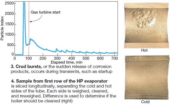
Frequency. Following unit starts, Sampson suggested sampling every 15 minutes for the first six hours, or until iron levels stabilize. He explained that monitoring during startups and shutdowns was particularly important because crud bursts—the sudden release of corrosion products from surfaces exposed to water/steam caused by thermal, chemical, and/or hydraulic shock—were more likely during transients. This was obvious from a plot of iron concentration versus time following startup (Fig 3). After resuming “normal” operations, Sampson suggested daily sampling at all locations until results are sufficiently consistent to support a longer interval.
Recommended tests. Run tests for total, soluble, and suspended iron, once or twice daily, until you accumulate the 30 to 60 data sets (the latter preferred) suggested for meaningful analysis and trending, Sampson said. He pointed out that soluble iron exists only for moments and test frequency can decrease to monthly if the baseline test results are consistently below detectable limits. The frequency of the wet total-iron test can be weekly if results are consistent with those from suspended-iron tests described below. Note that wet tests require use of a spectrophotometer.
Sampson presented a table of methods for monitoring iron. It showed that the minimum detection limits for most tests are 10 ppb and above—too high for powerplant use. The Millipore filter (0.45-micron filter) test for suspended iron is more accurate than wet tests, the consultant said, for two primary reasons: (1) Wet test methods don’t accurately measure total iron in steam drums. (2) Iron changes form and does not show up on the traditional wet tests unless digested.
The concentration of iron oxide (Fe3O4) in parts-per-billion terms has a detection limit of 10 ppb for the 1-liter sample specified by the Millipore filter test, which relies on a visual comparison of filter results and a calibrated printed chart. This comparison is similar in nature to the micro-Ringelmann smoke chart used by boiler operators before EPA was formed. To achieve the 2-ppb limit required, a 5-liter sample is drawn. However, this much water requires a vacuum pump and filter assembly to run the test.
Composite sampling uses the same 0.45-micron filter, but offsite analysis provides greater accuracy. Here’s how it works: A known volume of water passes through the filter and corrosion products accumulate. The filter is removed and weighed after exposure. The result is given in milligrams or micrograms per liter.
Additional analyses—such as x-ray diffraction—can provide information on oxide composition. Sampson recommended that soluble and total iron be analyzed by an outside lab quarterly to confirm the accuracy of plant tests. He stressed the importance of preserving samples to ensure accuracy.
Particle analysis. Wet-test results are valuable, Sampson continued, but they leave significant holes in the data stream. Every thermal, chemical, and hydraulic event liberates or produces metal oxides in the steam system. These events occur often and randomly and the majority of them cannot be detected by time-based iron sampling as described above. However, particle analysis provides a window into metal liberation and transport as it occurs (real time). Two different technologies can be used:
1. Particle counters count the number of particles in different size ranges. Testing indicates that the majority of iron transport occurs as particles smaller than 5 microns.
2. Particle monitors provide only one reading—a so-called index representing the total surface area of all particles passing through the sensor.
Deposit weight density is another analytical method at your disposal, Sampson told the group. It requires a tube sample from the first row of the HP evaporator. The sample is sliced in half longitudinally, separating the cold side of the tube from the hot side (Fig 4). Each side is weighed, cleaned, and reweighed. The difference is deposit weight density. Results are used to determine if the boiler should be cleaned.
In wrapping up his presentation, Sampson said that combining particle counts with wet test results “closes the loop” on Rankine cycle metal transport. The combination offers these three windows into the process:
1. Wet tests correlate particle index to iron transport.
2. Particle index provides real-time, continuous indication of the amount of iron moving through the system.
3. Deposit weight density confirms the amount of deposition on the tubes.
He finished by urging users to reduce corrosion-product formation by minimizing oxygen ingress, suggesting nitrogen blanketing of steam drums and the demin-water tank during shutdowns as well as steam sparging of the hotwell.
Controls, cybersecurity
The session on control systems and cybersecurity featured a presentation on security risks by Daniel Noles, TVA’s manager of controls engineering support. You can access Noles’s slides at www.ccusers.org. The follow-on discussion produced several observations and aphorisms worthy of note, including the following:
-
Plant operators are the industry’s most powerful assets. The job of the control system is to enable the operator to make the right decisions, at the right time, to achieve identified goals. The simpler you can make the control system, the better.
-
Plants have a mixture of legacy and modern control systems. The former don’t have the communications capabilities and security of new equipment and those vulnerabilities must be addressed.
-
Alarm management is a big challenge. However, it takes relatively little effort to have a large, positive impact on operations by eliminating alarms not of primary concern.
-
Tracking startup and shutdown data can identify abnormalities worth correcting.
-
Advanced pattern recognition: Early detection of impending problems offers considerable benefits. This technology is worth investigating.
-
It’s easy to make information available, but how do you make it more understandable and useful to the people who need it? Those who can answer the question will reap rewards.
-
NERC CIP standards 2 through 9 are relatively immature compared to other regulations the industry has to deal with. Version 4 is on the way but will not remain in effect for long; V5 is promised by late 2014. Possible wrinkle: Dept of Homeland Security, sources say, may supercede DOE as the CIP watchdog agency. Stay tuned.
-
The risk of being labeled “non-compliant” may be reducing the focus on security. At least some observers say, “how to comply” seems to have taken precedence over “security.” Reason: “Failure to comply” makes the news and initiates fines. There must be a balance between compliance and security was the attendees’ view. A cybersecurity program that achieves both compliance and security goals begins with people, users generally believe. Example: Don’t be tempted to pick up a USB stick in the parking lot and put it in a plant computer.
-
Technology leverages the process and people. The most complex decisions should be made by people; technology assures repeatability.
- Success in control-system decision-making and cybersecurity initiatives requires a champion with the ability to explain complex technical issues to executives.