
Open discussion sessions at 7F Users Group meetings are invaluable for keeping owner/operators informed about emerging issues, providing guidance on how to identify the onset of these problems, and suggesting action to take if you see something you were hoping not to find.
Workshop sessions, ranging from about an hour to half a day at the organization’s annual conferences, afford attendees the opportunity to come up to speed on technologies that can help make them more effective in their daily activities. With the minuscule staffing at most plants today, it’s difficult to find adequate time to expand your technical knowhow on the job. Take advantage of all the professional-development opportunities available to you at each user group meeting.
Last issue’s 7F report focused on discussion session topics from the 2013 conference, this article summarizes a few of the important workshop sessions. The material presented is generally applicable to all combined-cycle plants, not just those with 7F engines.
Borescope clinic
Mike Hoogsteden, field service manager for Advanced Turbine Support LLC, reminded 7F users that the intelligence gathered during periodic borescope inspections is critical to getting top performance from their engines. About half of the O&M personnel attending the 7F User Group’s annual conference were first-timers and benefitted considerably from Hoogsteden’s review of (1) what Advanced Turbine Support’s inspectors are seeing in the field and (2) several important Technical Information Letters (TIL) released by the OEM for this fleet.
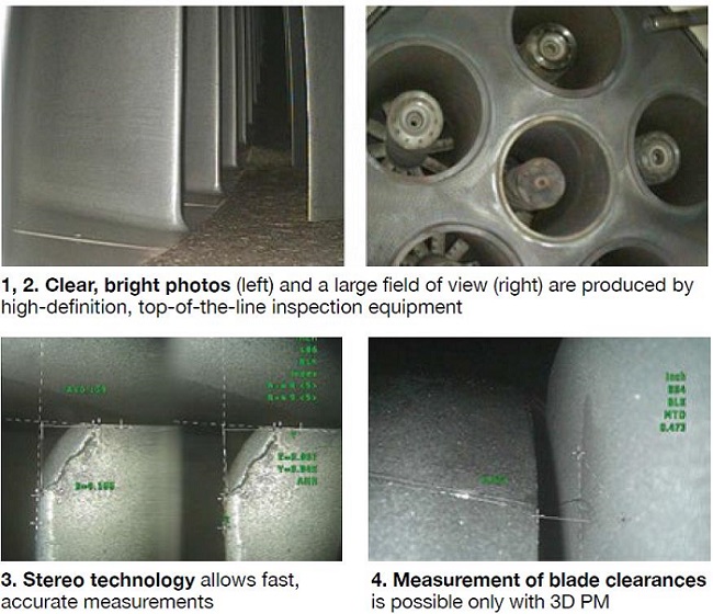
Hoogsteden began with a review of the latest borescope and nondestructive examination (NDE) tools available. They enable experienced technicians, with deep knowledge of the engine model being examined, to identify potential problems and evaluate the findings faster than previously possible. High-definition (Fig 1) and large field-of-view (Fig 2) are two attributes of modern top-of-the-line inspection equipment.
So-called stereo technology provides the borescope technician (1) a simple, accurate method of measuring linear dimensions in an image (Fig 3), (2) distance information between two points and a perpendicular line drawn to the line created by the two points, (3) the difference in height between points on two different surface planes, (4) a way to determine the surface area of a defect, and (5) the capability to measure the length of a non-linear defect or feature.
Hoogsteden next described 3D Phase Measurement (PM)—a new full-screen, on-demand optical measurement technology—as an “exciting breakthrough” for borescope inspections. He said it scans the part surface and creates a 3D map that allows technicians to perform all measurements and views right on the 3D surface. This technology also allows technicians to determine turbine blade clearances (Fig 4).
Top technicians supported by state-of-the-art diagnostic equipment and the capability to perform some critical maintenance remotely (including the removal of protruding shims close to liberation, minor blending, etc) permit the plant manager to track concerns with confidence, thereby allowing cost-effective condition-based maintenance planning.
Be sure your stake is well done. TIL 1870R1 (Mar 5, 2013) requires owner/operators to check for first-row blade migration on F-class compressors that received an R0 re-installation between January 2008 and January 2013. Concern is that there may be insufficient interference between the stake marks and the blades, and that the airfoils may have moved forward. A small population of turbines reportedly has had migration events related to improper blade installation.
This technical information letter is a sequel to TIL 1796 (Apr 25, 2011) which required 7F owners to check for forward migration of R0 blades both visually and physically. The latter is defined a simple “lift and tug” on each blade (not a hard yank) to confirm axial restraint. Blades that do not pass this test must be restaked.
Reasons blades might migrate: (1) Stake marks are undersized and unable to prevent the blade from moving forward. (2) The radial gap between the blade dovetail and slot bottom is excessive, allowing the blade to slip over the stake marks. In the extreme, axial movement is conducive to compressor blades rubbing against the casing bellmouth, damaging both the blade and the rub ring.
Improper depth, diameter, and/or height of stake marks, and improper use of feeler gauges for gap checking, are the root causes of most blade migration events. Coincidentally, an insurer reporting at another user conference said that three-quarters of all powerplant losses had a worker component—including ineffective training, supervision, etc.
Hoogsteden told the 7F users that TIL 1870R1 goes beyond TIL 1796 by requiring owner/operators to check for biscuit rotation where this blade retention solution has been installed. It also calls for verification of staking measurements and radial gaps during major inspections when the bellmouth can be jacked up to permit access for inspection.
 For those users not familiar with biscuits, Hoogsteden explained that after several blade installations there may not be sufficient room along the edge of the slot bottom for staking and an insert (biscuit) is inserted into a cut-out in the first compressor wheel to perform the same function as peening. A problem associated with biscuits can be their rotation, generally precipitated by improper staking.
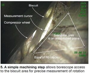
If you are not familiar with TIL 1870R1, contact your GE representative for a copy. It explains how the biscuit should be staked and how much rotation is permissible. In the TIL, the OEM suggests the use of a mirror to facilitate visual inspection of the biscuit. The speaker said Advanced Turbine Support believes the mirror is not a sufficiently comprehensive aid for this purpose and might result in drawing erroneous conclusions. The company is validating an alternative approach introduced by a customer that with simple machining allows borescope access to the biscuit area for precise measurements of rotation (Fig 5).
Rocking solution conducive to stator blade twisting. TIL 1769 (Dec 1, 2010) instructs 7F owner/operators on how to inspect their gas-turbine compressors for stator-vane rocking in stages S14 through S16. Much has been published in the CCJ on the subject of vane rock attributed to worn hookfits, with many affected users opting for pinning of the individual square-based vanes into segments to promote rigidity and prevent the release of vanes into the air stream. This solution, developed by Rodger Anderson of DRS-Power Technology Inc, has proved effective over the years.
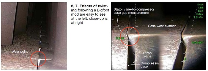
One of the OEM’s solutions for dealing with vane rock is its so-called Bigfoot mod which involves onsite machining of the casing to create a new hook fit for the vanes. Inspections by Advanced Turbine Support of stages S14-S16 following implementation of the Bigfoot mod indicates twisting of stator vanes in some cases. Such twisting is conducive to casing wear and tear because the Type-409 stainless steel compressor vanes are harder than the cast steel casing (Figs 6 and 7). Hoogsteden suggested that users experiencing twisting might want to trend the casing wear over time.
The editors asked a compressor expert what impact twisting might have on performance. A back of the envelope calculation assuming a nominal 2.5-deg twist could cost from 0.5 to 1% in compressor efficiency.
Wait, there’s more. Hoogsteden presented thumbnails and offered experienced commentary on several more TILs during his presentation. Here are excerpts from the editors’ notes:
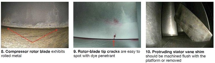
• 1509R3 addresses R0, R1, and S0. It recommends annual visual inspection for R0 root cracking, R0/R1 tip discoloration, rolled metal (Fig 8), and/or tip loss. The TIL provides detailed recommendations if any of those deterioration mechanisms are identified. Example: For S0 stator vanes, inspection personnel are urged to look for trailing-edge cracks; if found, immediate replacement is recommended.
Advanced Turbine Support is not in complete agreement with the OEM’s recommendations. It believes that annual visual inspections are not sufficiently comprehensive and have the potential to miss small or tight indications that could result in blade liberations and a catastrophic failure. The company’s inspection experts have identified multiple rotor-blade tip cracks (Fig 9) with visible dye penetrant that were not seen during unaided visual inspections.
• 1562 suggests monitoring the condition of compressor shims and the corrective actions necessary to mitigate the risks of migrating shims on both E- and F-class machines (Fig 10). There are 20 possible shim locations in the first five stages (R0 through R4) of 7F units and they are spaced approximately 60 deg apart from each other.
• 1638 addresses, among other issues, F-class R1 case-off ultrasonic inspections for dovetail distress below the blade platform. The testing interval is 8000 fired hours or 150 fired starts, whichever occurs first. This recommendation is modified for peaking units performing more than 150 annual starts to just before and following the peak season. Inspectors have found four such cracks to date.
 Advanced Turbine Support recommends users heed caution and opt for in-situ inspections at more frequent intervals. In the case of the last in-situ discovery, Hoogsteden believes there was a high probability of major damage before the next OEM-recommended inspection interval, potentially leaving LTSA customers at risk.
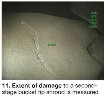
• 1858, 1859, and 1863 concern the inspection of second-stage buckets on the 7FA.03 (7241+e, enhanced compressor). The first advises users to perform the inspections recommended in the document for second-stage buckets of original and modified design to mitigate the risks associated with tip-shroud creep (Fig 11). The second alerts users of the potential need for increased borescope inspections when installing second-stage buckets of original or modified design. The third TIL alerts users of the potential need for increased borescope inspections if the unit operating profile is changed.
• 1884 addresses clashing on bottom half of 7EA compressors, but Advanced Turbine Support has growing concerns with F-class units as they have discovered increasing evidence of clashing in the field including one such finding in the top half of the compressor.
Boost HRSG performance, improve the bottom line
The performance thieves lurking in many heat-recovery steam generators sometimes can be eliminated with relatively little effort and at low cost, Lester Stanley, PE, told owner/operators attending HRST Inc’s half-day HRSG workshop at the 7F Users Group conference. The boiler expert focused on the following performance thieves during his opening presentation:
- Gas baffling.
- Gas-side fouling.
- LP economizer recirculation.
- Buoyancy instability/vapor locking.
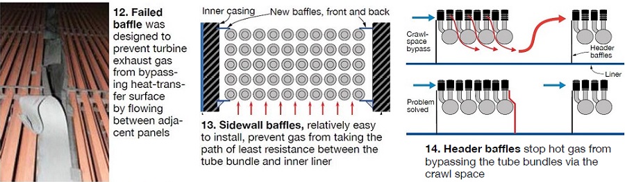
Baffles force turbine exhaust gas through the tube bundles, maximizing heat transfer and performance. Even gaps of only 2 in. between adjacent tube panels, between tube panels and the inner liner, and between headers in the crawl-space area, can cause significant losses, Stanley told the group. Baffle integrity in evaporator and economizer sections is particularly important, he said.
Damaged or missing baffling is easy to identify during a gas-side inspection (Fig 12) and relatively easy and inexpensive to correct with standard carbon-steel components and conventional welding techniques (Figs 13, 14). Perhaps the most costly component of baffle repair and/or replacement is the installation of scaffolding. Therefore, it makes good sense to do this work when cleaning tube panels, which also requires scaffolding.
Stanley noted that thermal performance loss is not the only adverse impact of ineffective baffling; it has been known to contribute to flow-accelerated corrosion (FAC) as well. Also, when baffles in the firing-duct area are not in good condition, duct-burner flames can be disrupted and tubes and the SCR can suffer thermal damage—all in addition to performance loss.
Though baffle work is relatively simple to do, if your unit has excessive gaps in many locations, the plant maintenance budget might not be able to swallow the whole refurbishment project in one gulp. Stanley discussed one such case where performance modeling provided justification and prioritization of the work.
Some gap locations create more performance decrease than others, he said. In the real-world example described, Stanley said that the annual benefit of coil-to-coil baffle fixes in all six access lanes of an F-class HRSG was about $1 million. However, baffle restoration in only two of the lanes produced 60% of that benefit making the investment decision an easy one. In this case, the plant reported a 2 MW increase in output after repairs were made.
Gas-side fouling, as most attendees knew, can be caused by one or more of the following: rust, ammonia salts, sulfur compounds, and liberated insulation. They also were aware that the consequences of fouling include an increase in gas-turbine backpressure, a thermal-efficiency penalty, and the release of particulates up the stack, especially at startup.
But many were not sure of the financial impact of fouling. Stanley worked up a short calculation that showed gas-turbine power production decreased by 0.105% for each 1-in.-H2O increase in backpressure. For a 7FA with a nominal rating of 183 MW at ISO conditions, this translates to a “de-rate” of 192 kW. In addition, fouling reduces HRSG thermal efficiency because it reduces heat transfer and steam production.
Someone asked about the optimal time for cleaning fouled heat-transfer surfaces. Stanley said this was an economic decision and could be different for every plant. He added that high backpressure often drives the decision, to avoid the consequences of an unnecessary turbine trip. Next, the boiler expert suggested that plants develop their thermal-performance and backpressure yardsticks to determine the optimal time for cleaning.
Stanley pointed out that rust is relatively easy to remove, SCR ammonia salts not so. Regarding the latter, he warned about the difficulties in cleaning tube bundles after they had bridged over—that is, totally packed to the fin OD with ammonia salts. “Clean before crisis,” Stanley urged.
The next 10 minutes or so was dedicated to a review of the types of cleaning, the effectiveness of various media, and the advantages of so-called deep cleaning—a process developed by HRST Inc. Stanley said that, in general, best results in the cleaning of fouled finned-tube surfaces have been achieved using CO2 and compressed-air blasting, perhaps in series. Water deluge or hydroblasting can do the job in some instances, he continued, but waste collection and disposal would likely militate against the use of water.
The next performance thief Stanley discussed was LP economizer recirculation. Bryan Craig wrote in a recent issue of HRST’s Boiler Biz that recirculation often is used to raise the temperature of condensate entering the LP economizer above the turbine-exhaust dew point to minimize corrosion of panels in the back end of the unit.
However, this comes with a cost. Recirculating water flow to increase the inlet temperature reduces overall output from the HRSG in a small, but measurable way, he stated. The amount of performance reduction depends on the water-temperature set point, and also the location from which the recirc flow is taken.
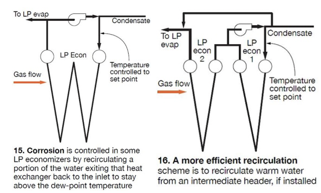
Some LP economizers recirculate a portion of the flow from the economizer outlet back to the inlet to achieve temperature control (Fig 15); others recirculate from an intermediate point within the economizer, design permitting (Fig 16). HRST engineers have concluded that if recirc must be used, it is more efficient to take the flow from an intermediate point than from the economizer outlet. The temperature set point also comes into play: Reducing the set point improves efficiency.
Craig used Fig 17 to illustrate this point. The chart is based on a typical F-class HRSG with a 12-row LP economizer and a condenser hotwell temperature of 105F. If recirc flow is taken from the economizer outlet, reducing the temperature set point from 140F to 130F increases steam-turbine output by 160 kW. Assuming the plant operates 5000 hr/yr and is paid $50/MWh for the electricity it produces, the 10-deg-F reduction in the set point is worth $40,000 yearly. For the 130F set point, extracting recirc flow from the midpoint of the economizer increases steamer output by another 180 kW, more than doubling the annual revenue gain to $85,000.
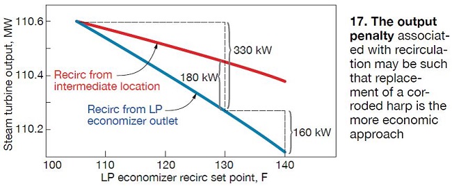
Eliminating recirc altogether, and allowing cold water to enter the LP economizer, increases steam-turbine production by 330 kW, which is worth about $82,000 per year. This suggests it may make sense to forego recirculation and plan on replacing the last one, two, or three rows of LP economizer surface every eight years or so, give or take a couple of years. Also worthwhile considering: The first time you replace the back-end surface, switch to an alloy material suitable for the wet environment and eliminate the need to do it a second.
Buoyancy instability. Stanley began the final segment of his presentation by reviewing the performance loss caused by buoyancy instability in panelized economizers. Nearly all economizers have some down-flowing tubes, he said; most have down-flow in half the tubes. Buoyancy instability causes flow to stagnate in some of the down-flow tubes, or to reverse direction. When water does not flow as designed, the effective heat-transfer surface is reduced and heat absorption decreases.
Also, stagnant and reverse-flow tubes become hotter than neighboring tubes increasing the level of stress. The risk of this happening is greatest at low loads. Hundreds of thermal cycles can occur within a day, leading to fatigue failures in less time than you might think. Modification of flow circuitry can correct the issue.
If a performance assessment advises that buoyancy instability is a problem early in the life of a unit, changing the location of splitter plates in the upper header should be considered to optimize the flow pattern. Stanley said the relocation of splitter plates is not as difficult as it might appear. In some cases, he said, it can be easier than plugging economizer tubes.
Buoyancy instability in return-bend economizers causes water in some circuits to flow very slowly or not at all, others to flow quickly. If the gas temperature is above the saturation temperature, stagnant tubes will vapor-lock—that is a steam bubble trapped in the return bend will block flow, generally until unit load is high enough to clear it. It is difficult to modify existing systems to correct this problem.
Go beyond visual inspections
Boiler expert Bryan Craig, PE, urged users to consider going beyond the “standard” visual inspection of their heat-recovery steam generators. Unit age, cyclic operating history, and findings during previous inspections are among the variables that should be factored into your decision, he said.
Craig acknowledged that a simple walkdown of the gas side is all you need to find problems such as liner/insulation damage in the hot-gas path, fouled catalyst and heat-transfer surfaces, tube damage, leaking penetration seals, etc, but suggested a lot more could be going on internally that you’d want to know about. One of the speaker’s objectives was to familiarize owner/operators with some of the inspection techniques at their disposal and explain how these technologies are capable of helping them.
Desuperheaters were Craig’s starting point. A great deal has been written about them in the last 10 years—the probe type, in particular. Craig said probe-type desuperheaters on HRSGs cycling once a week or more should be inspected annually. Look for cracking or distress on the desuperheater assembly, check nozzles for looseness and plugging, verify springs are intact. Also, use a borescope to assure liner integrity and the absence of pitting/wear at the downstream elbow. If DCS data suggest overspray, check piping for cracking.
Borescopes were offered as good screening tools for HRSG inspections—qualitative, not quantitative. Examples: Find evidence of FAC; check condition of superheater, evaporator, and economizer tubes and headers to the extent possible (access often limited). One suggestion was to install borescope ports in headers to improve access.
Two inspection techniques introduced to the group were Lotis (Laser Optic Tube Inspection System) and Iris (Internal Rotary Inspection System). “Introduced” is appropriate because no owner/operator had heard of either previously. Good reason regarding Lotis, which relies on a spinning laser to determine tube wall thickness by subtracting the ID from the OD, because it is not currently available for HRSGs. Iris measures the distance from the center of the tube to both the ID and OD using ultrasonic technology. Access to individual tubes is required and tubes must be filled with water.
Tube sampling is a destructive inspection option for users. This has to be done selectively—perhaps based on borescope findings—because of the expense involved. Tube deposits and failures are two reasons for sampling. But identifying the optimum sampling location can be challenging, Craig noted. He suggested removing 3 ft of a degraded or failed tube for laboratory analysis—including alloy verification, hardness, dimensional checks, and deposit/scale/oxide analysis and measurement.
Magnetic-particle and dye-penetrant testing were cited as the best/most practical methods for identifying surface cracks in suspect areas, including these:
- Tube-to-header joints in the economizer inlet pass, at all pressure levels, after 500 cycles.
- Superheater and reheater tube-to-header joints, if warped tubes get worse over time.
- At or near welds in the base tube material.
- Vent and drain lines.
Craig told the group dye penetrant testing has several advantages and a few negatives. On the plus side: Flaws are very visible, technicians generally can be trained quickly (although experience is valuable), cost is low. Disadvantages include the following: Proper cleaning of the suspect area is required, fumes can be toxic in confined spaces, results can be misinterpreted by inexperienced personnel.
Magnetic-particle testing typically is used to find fatigue cracks in ferritic materials that have been in service for a few years, the speaker said. Advantages over dye pen include speed, ability to perform in damp environments, use in areas with poor ventilation. It is not recommended for components with complex or tight geometries.
Ultrasonic thickness testing finds greatest use in tracking flow-accelerated corrosion (FAC) and external corrosion. Discussion of UT flaw detection followed, with Craig explaining both the shear-wave and phased-array techniques and illustrating how welds are examined. He warned that it takes time and experience to get meaningful results with shear-wave UT. Phased-array UT is much faster.
Most attendees were familiar with UT because of its extensive use in gas-turbine inspections. The volumetric technique, like radiation, is capable of subsurface flaw detection; but UT has none of the safety hazards associated with radiation. Its ability to determine the depth of a crack, for example, is particularly valuable to owner/operators. Depending on geometry, a high level of skill and experience may be required to properly interpret the data and get meaningful results. Mockups sometimes are required to calibrate the test. Craig suggested that owner/operators make sure the technician assigned to their jobs has a Level 2 certification—at a minimum. Also, that you receive a “scan plan” before work begins.
Positive Material Identification capability is valuable when conducting HRSG inspections. If questions arise, PMI can quickly determine the chemical composition of metal surfaces. A hardness tester is another screening tool you should have, particularly if P91 material is installed in your main and hot-reheat steam systems. Hardness testing looks easy, but keep in mind that bad data are easy to get. Replication is a technique that creates an image of a metal’s grain structure; it supplements hardness testing in the evaluation of P91 condition. This inspection work should be done by a qualified and experienced metallurgist.
Thermal imaging (thermography) is valuable plant-level technology for detecting and quantifying hot spots, areas of missing insulation, exhaust as leaks, etc. Finally, Craig suggested to attendees that careful review of DCS data often can pinpoint problems and that trending of data is valuable for monitoring solutions. Issues that can be identified by reviewing DCS data include the following: poor control of feedwater flow, improper schedule for steam drains during startup, fluctuating drum level, desuperheater cycling, spraying to saturation, etc.
Quickly repair cracks in liners, perf plates
The third segment of the 7F HRSG workshop, presented by Stanley, included useful maintenance tips on inlet and firing ducts. He began with the basics. HRSGs typically are insulated internally using a floating liner, Stanley said. Outer casing is of carbon-steel plate, separated from the floating sheet-steel inner liner by ceramic-fiber blanket insulation. The casing provides a gas-tight seal, he continued, and supports the liner. Insulation protects the casing from high exhaust-gas temperatures—thereby minimizing heat loss and casing thermal expansion, and allowing the use of carbon steel for both the casing and structural members. The floating liner keeps insulation in place and allows for thermal expansion of hot-face components.
Next, Stanley ran through the details of liner construction and repair. He used essentially the same material for this segment of his presentation as colleague Ned Congdon, PE, had shared with plant personnel at the Western Turbine Users Inc meeting two months earlier. Stanley discussed inlet-duct problems as Congdon had done, acknowledging that while the exhaust stream from the 7FA is not as turbulent as that from the LM6000, it still demands respect.
He stressed not tolerating any rattling or spinning parts, or exposed insulation. Gas-flow distribution devices were not part of Congdon’s presentation, but Stanley covered material distress in turning vanes and the perforated plate. He suggested inspecting carefully for cracking of turning vanes and noting that cracked vanes often can be removed with no duct-burner effect, but a proper engineering evaluation is needed to support decision-making.
The perforated plate likewise must be inspected for cracking. If you find evidence of such, Stanley suggested that you begin planning to replace the plate with an upgraded version. Sometimes sections of the perf plate can be removed with no duct-burner effect, but make sure a CFD analysis agrees beforehand.
Stanley closed with a review of firing-duct oxidation and creep damage generally caused by improper specification or use of materials. Creep strength declines logarithmically with temperature, the speaker reminded, and offered the following limits on use of typical steels:
- Carbon steel, 700F.
- Cor-Ten, 1100F.
- Type 409 stainless steel, 1200F.
- Type 304 stainless steel, 1500F.
- Type 310 stainless steel, 1800F.
Fuel-nozzle flow testing
Sometimes you think you know something until you listen to someone who really knows that something, making you aware of how little you really know. Fuel-nozzle flow testing may be one of those things. Mitch Cohen of Orlando-based Turbine Technology Services Corp (TTS), a respected combustion-system expert, presented work on that subject developed by the Electric Power Research Institute (EPRI). Judging from the questions, there were some bona fide subject-matter experts at the 45-min 7F workshop for owner/operators, but there also were a few others at the opposite end of the knowledge spectrum.
Flow testing is a longtime key component of both the fuel-nozzle manufacturing and repair processes, even for diffusion and early DLN systems having NOx targets of 25 ppm or higher. For these older systems, acceptable combustion performance could be achieved with a higher degree of combustor-to-combustor variation in the fuel/air ratio than today’s more sophisticated combustor designs require. Consequently, methods used to flow test older model fuel nozzles did not have such stringent requirements for accuracy.
However, the evolution to advanced low-NOx combustion systems—such as the DLN2.6—demands more accurate, reproducible, and repeatable measurements and tighter control of a nozzle’s effective flow area. This accuracy and tighter control extends both to the absolute area of nozzles, which impacts the dynamic characteristics of the combustion process, and to the variation in area among sets of fuel nozzles and components, which impacts—most importantly—margin from lean blowout (LBO). Emissions and dynamics also are affected.
Cohen’s presentation announced the availability of the EPRI technical update 1023970, “Fuel Nozzle Flow Testing Guideline for Gas Turbine Low-NOx Combustion System,” that he, Leonard Angello of EPRI, and Hans Van Esch of Turbine End-user Services co-authored to accomplish the following:
- Assist operators in the selection and qualification of fuel-nozzle repair/flow-test vendors.
- Provide a detailed methodology for obtaining accurate flow-test results, which discusses both equipment and flow-test procedures.
- Identify the steps involved in validating flow-test results.
- Provide guidance on both how to interpret flow test data and how to use that information to establish criteria for returning nozzles to service.
Cohen told attendees that optimal operation of 7FA DLN2.6 combustion systems requires the balancing of several competing requirements, including these:
- Maintaining NOx emissions at less than 9 ppm.
- Preventing LBO trips.
- Maintaining the amplitudes of hot, cold, and chug tones within acceptable limits.
- Achieving the required load turndown while holding CO emissions within permit limits.
Tight control of fuel/air ratio is critical to these goals, he said, adding that exacting fuel-nozzle flow testing is required to assure this level of control can be achieved. However, the experience of TTS in troubleshooting DLN operational problems, Cohen noted, is that operations personnel sometimes are unaware of the basic requirements of flow testing or how to evaluate data they receive. In many instances, he added, operators are not even sure if they have received flow-test data for nozzles that are in service, and/or they are unable to locate this information. These findings helped provide the incentive to develop the EPRI guideline.
What is flow testing? Cohen began his tutorial by answering this question. He said, “It is the measurement of the effective flow area, or simply the ‘effective area’ of a flow passage, usually expressed in square inches.” For a standard venturi nozzle measurement is relatively simple, but for more complicated geometries—such as a fuel nozzle—the effective area must be determined in a flow test rig. Cohen continued: “In a flow test rig, if we know precisely the mass flow and gas composition (dry air) we can calculate the effective area by measuring the upstream and downstream pressures and the temperature.”
Flow testing is important, he said, to achieve equal (that is, as close to equal as technology allows) fuel flows through the respective fuel passages (PM1, PM2, PM3, Quat) of each combustor by minimizing the variation in effective area from can-to-can. Cohen pointed out that, for a given fuel manifold, each combustor sees the same pressure and temperature conditions and that any difference in fuel flow among the chambers is due solely to differences in effective area.
Another reason flow testing is important is that failure to operate at the design pressure ratio across fuel nozzles is conducive to combustor dynamics issues. Achieving the correct pressure ratio demands high accuracy in measuring the targeted effective area of the fuel nozzles. Cohen used this as a segue to discuss how the reliability of flow test results are validated. Accuracy, repeatability, and reproducibility of the data are vital to enable proper tuning of the engine. He defined those terms this way:
- Accuracy is the deviation of the measured effective area from the actual effective area.
- Repeatability is the ability of a measurement system—a flow test rig in this case—to reproduce a measurement while operating under an unchanging set of conditions.
- Reproducibility is the ability to reproduce a measurement under different conditions of pressure, temperature, and humidity, and at different points in time. It presumes the test rig has been broken down and rebuilt between measurements. Reproducibility also is an indicator of the consistency of the setup and testing procedure used by different, or the same, technicians responsible for measurements.
The EPRI guideline recommends these quantitative limits for each validation parameter:
- Accuracy within plus/minus 0.75% of a calibrated master standard part—defined as one whose effective area has been measured by an independent calibration lab using instrumentation traceable to the National Institute of Standards and Technology.
- Repeatability: Two standard deviations; less than 0.5% of the average measurement.
- Reproducibility: Two standard deviations; less than 0.75% of the average measurement.
Having valid measurements is only table stakes, however. How this information is used to develop test specifications and to qualify/reject fuel nozzles is the owner/operator’s challenge. First step, Cohen said, is for the operator and vendor to discuss and agree on the limits for can-to-can variation in effective area for each flow passage (PM1, PM2, etc). This typically is expressed as a limit of the percentage calculated by subtracting the minimum effective area from the maximum and dividing that by the average effective area. He added that many vendors offering flow-test services use this as the only qualifying criterion.
But that is a mistake, Cohen believes. For each gas passage, the average effective area also should be within a certain percentage of a specified target value, calculated by subtracting the targeted effective area from the average and dividing the result by the targeted effective area.
He went on to illustrate, by use of a series of charts available to users on the 7F Users Group website, how numbers written into a specification can appear correct but may be unsatisfactory for assuring proper tuning of advanced DLN combustion systems. The example presented showed two sets of PM3 assembly flow test data having the same average effective area and the same max-to-min range, 4.0% in this case. For the first data set, the variation from the average effective area was +2.1%, -1.9%; for the second set, +0.6%, -3.4%. Both sets of numbers satisfy the spec, but the second set does not meet the intent of the spec.
Here’s one reason why: One combustor always will be the lowest flowing of the 14 and the first to flame out if operated too lean. Minimizing the variation in average effective area—at the low end in particular—will provide more margin from potential LBO. Another reason: High- or low-flowing cans can result in excessively high dynamics in only one or two combustion chambers and this can lead to high NOx emissions when the entire combustion system is tuned to reduce the dynamics in the one or two affected cans. CCJ
