
Analytical thinking a common thread through presentations on HRSG damage mechanisms, faster steam production, repurposing of steam-plant condensers for combined-cycle service, integration of solar tower/thermal energy storage technologies into combined cycles
What’s eating up your LP evaporators: FAC or LDI?
Most O&M personnel at combined-cycle and cogeneration plants powered by gas turbines are aware that tube/pipe-wall thinning attributed to flow-accelerated corrosion (FAC) is a frequent cause of pressure-part failures in the low-pressure section of heat-recovery steam generators (HRSGs).
Less common, but also of concern, is damage caused by liquid droplet impingement (LDI), say David Moelling, James Malloy, Marc Graham, Mark Taylor, and Andreas Fabricius of Tetra Engineering, an independent consultancy with offices in the US and Europe. Boiler and power-piping inspection and failure analysis are among the company’s specialties.
An evaluation of “Design Factors for Avoiding FAC Erosion in HRSG LP Evaporators” was presented by this group of Tetra engineers at the ASME 2013 Power Conference, last summer, in Boston. The following is an overview of that presentation. Get the details by ordering the meeting proceedings from ASME and reading POWER2013-98213.
Recall that FAC involves the accelerated dissolution of the protective magnetite layer that forms naturally when carbon steel is oxidized in water or in a two-phase water/steam mixture. While extensive research over the last four decades has led to a good overall understanding of the essential damage mechanism—that is, dissolution rate depends on local water chemistry, temperature, and fluid velocity—work continues on understanding the relative importance of the individual parameters on wear rates and on improving the accuracy of predictions.
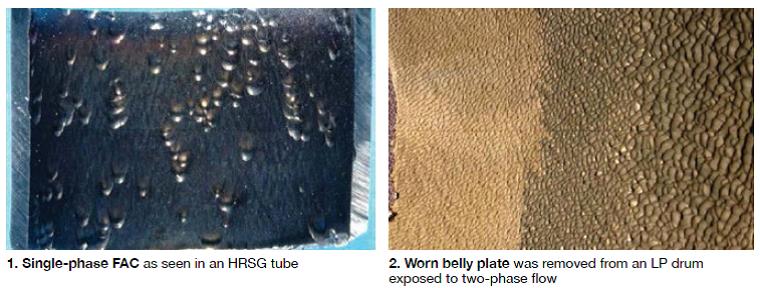
FAC can occur in both single- and two-phase flow conditions. The latter can accelerate FAC progression, principally by increasing the flow rate of water near the metal surface. It is possible in some cases to differentiate between the surface appearance of a pipe or tube subjected to single-phase FAC and one experiencing two-phase FAC.
Surfaces exposed to single-phase FAC are usually ascribed an “orange peel” appearance, with pits resembling many horseshoe prints, all oriented in the same direction (Fig 1). Surfaces exposed to two-phase FAC can have a wider range of appearances—from the so-called “tiger stripe” pattern to a black and shiny scoured surface to an “orange-peel” pattern very similar to single-phase FAC (Fig 2).
Mechanical erosion, like FAC, can lead to thinning of steel components. Water at high velocity can erode even the hardest materials—including diamond and tungsten carbide. The mechanism of interest in LP evaporator circuits is LDI. It causes material loss through the repeated impact of high-velocity droplets on a tube or pipe wall surface.
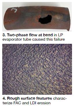
Common locations for LDI are in bends or near obstructions in piping carrying wet steam. Water, in the form of droplets or high-velocity liquid in the two-phase stream does not follow the contour of the pipe; their inertia causes them to stay on the original trajectory and impinge on downstream surfaces. This explains why LDI thinning is typically found in the “line of sight” of the original flow trajectory.
Damage caused by LDI is characterized by a rough surface, similar to cavitation pits, with little or no surface oxide. The wear rate attributed to LDI in a given material depends on several factors, including these:
- Impact velocity.
- Droplet size.
- Impact frequency.
- Liquid density.
- Vapor density.
- Viscosity (temperature).
The effect of impact velocity has been assessed by researchers. The resulting empirical formulations, which identify a threshold velocity below which no mechanical erosion occurs and can predict wastage rates by a power law relationship to velocity. There is disagreement on the exact velocity dependence of LDI and a considerable disparity on the value ascribed to that threshold velocity, ranging from “several tens of meters per second” to more than 100 m/sec (330 ft/sec).
Whereas FAC can be mitigated, if not eliminated, by keeping the water chemistry (pH and oxidation reduction potential) within the appropriate control band, the effects of LDI cannot. Only a change to flow geometry and/or local process conditions can lower the rate of surface loss.
As local flow velocities in a pipe or tube increase, the relative contribution for material loss transitions from FAC to LDI erosion, which first acts on the protective magnetite surface and later on the base metal once the oxide has been removed. For this reason, some have found it useful to divide LDI into LDI erosion and LDI corrosion. The former refers to purely mechanical wear at high flow rates; the latter encompasses mechanical erosion coupled with the corrosive action characteristic of FAC.
The notion that FAC and LDI could act in a complementary fashion is fittingly described by the term erosion/corrosion, which had been used to describe the range of flow-related mechanisms that could cause pipe thinning.
 FAC, LDI in LP evaporators. FAC, and to a lesser degree LDI corrosion, is known to occur in HRSG LP evaporator circuits, at times requiring extensive repairs and even full-module replacements. Single-phase FAC can occur in any area where there are high local flow velocities exist—such as tube bends at the lower header and feeders, and connecting piping between header and downcomer. There is a noticeably higher amount of thinning of the tube walls at locations just above the feeder pipes entering the header.
Two-phase FAC has been observed in tube bends at the upper header (Fig 3), the inside surface of the upper header, risers and drum internals such as separator plates. LDI wear is potentially possible in the same areas if flow velocities are high enough (Fig 4).
Tubes near the edge of the bundle adjoining the casing or center baffles may show accelerated thinning because of higher local gas temperatures which increase boiling rates, and hence local flow rates. The higher temperatures occur when hot gas bypasses upstream tubes along channels, such as the one formed by the gap between the casing wall and the edge tube.
Avoiding FAC and LDI. HRSG design and water chemistry play important roles in determining susceptibility of the LP evaporator circuit to FAC. Operating parameters such as water chemistry (pH and dissolved oxygen) can be adjusted, whereas the design, once in place, cannot. The emphasis here is on identifying the principal design factors that would render a HRSG more resistant to both of these degradation mechanisms.
Process conditions (flow velocities and flow regimes) in the LP evaporator are sensitive to small changes in heat transfer and load conditions. This is particularly true in units with very low pressures in the boiling zone—such as those making LP steam only for deaeration. Low pressures mean that there is a high void fraction in the two-phase region.
LP evaporator process conditions will vary with changes in HRSG steam production, which is impacted by gas-turbine load and (if installed) operation of supplementary firing. Therefore, progression of FAC and LDI wear can depend on the HRSG load profile over the operating life of the unit.
Not everyone agrees liquid droplet impingement is a unique damage mechanism
Liquid droplet impingement (LDI) is a phenomenon whose existence, while believed by some to make sense, has not been fully vetted by the scientific community in the minds of at least a few of the world’s leading authorities on powerplant water chemistry and HRSG damage mechanisms.
One of the presenters at the 2013 International Conference on FAC in Fossil, Combined Cycle/HRSG, and Renewable Energy Plants told the editors, that in his opinion, there was “nothing robust in the literature about LDI.” He said the topic was raised at the conference and the consensus opinion was that everything thought to be LDI turned out to be “just old FAC occurring at a high rate” when analyzed under a microscope by experts.
The chemist/metallurgist believes LDI might be one of those “stories” that circulates around the industry, developing a life of its own, but with no real basis in science—a Bigfoot or Loch Ness Monster of sorts. Everything mechanism-related, he continued, points to very high rates of FAC in two-phase environments; the droplets just increase the rate of mass transfer.
More to come on this topic in future issues. If you want to join the dialog, write bob@ccj-online.com.
Modifying a combined cycle to improve operational flexibility
Michael Radovich of URS, Princeton, NJ, described in his presentation, “Agile HRSG” (POWER2013-98255), a design enhancement for conventional reheat heat-recovery steam generators intended to enable faster startups. The modification might also be suitable for existing HRSGs. The operational flexibility provided by Radovich’s design could help a plant improve its dispatch position and revenue stream, particularly where a grid operator is looking for reliable generation to back up must-take intermittent renewables.
The mod also would allow a combined-cycle plant to operate its HRSGs as standalone auxiliary boilers, and its gas turbines in the simple-cycle mode without the need for bypass stacks. The only additional equipment required to make such operational improvements a reality, according to Radovich, are external blowers, a preheater, and a burner connected to each boiler’s diffuser (the transition piece connecting the GT exhaust duct to the HRSG). The preheater uses water from the HRSG’s HP economizer to raise the temperature of ambient air prior to combustion (Fig 5).
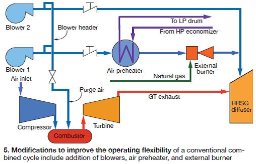
When GTs are shut down, this auxiliary equipment is placed in service; it provides enough flue gas to allow the HRSGs to operate as small auxiliary boilers. The steam produced pressurizes the drum, heats the steam lines, provides sealing steam for the steam turbine, and allows a vacuum to be maintained in the condenser. Sufficient steam would be available to synchronize the steam turbine, Radovich said.
The external burner system also can be used as a duct burner. During hot weather, it can provide the HRSG with additional heat to increase steam production.
When inspection and/or maintenance of Rankine cycle equipment is required, the plant can be lined up this way for simple-cycle operation: The HRSG, condenser, circulating-water system and steam turbine are shut down, and the boiler is drained. The blowers then are turned on and inject tempering air into the GT exhaust stream. Ambient air reduces the exhaust temperature to that required by the SCR for optimal NOx control. Important to note is that the temperature of the ambient air/flue gas mixture does not cause distress to the uncooled HRSG heat-transfer surfaces.
Equipment specs. The two blowers incorporated into each GT/HRSG string should be sized to temper the diluted exhaust stream to about 780F; Radovich considers this the ideal temperature for good SCR performance. The combustor, he says, should be able to heat air flow from one of the blowers to about 900F, which is consistent with the desire to operate the steam turbine at low load.
A work in progress. Radovich acknowledged that his proposed cycle enhancement might be difficult to retrofit on some existing combined cycles because of the space required to install the external burners and heat-exchanger skids. Other possible sticking points that should be considered, he said, are listed below. All suggest the need for engineering analysis.
- HRSG drums might not be suitable for the low-pressure steam flows produced by the external combustion system.
- Low stack temperatures may cause ammonium bisulfate to deposit on preheater heat-transfer surfaces.
- The HRSG may not be able to handle the additional tempering-air flow.
- The steam turbine may not be capable of operating for extended periods at the low steam flows and pressures associated with the external combustion system.
In wrapping up his presentation, Radovich said the design described in his paper probably could be improved. For example, it may be more economical to fire an external duct burner with one of three 33% tempering air fans rather than one of two 50% fans.
A rigorous economic analysis also is necessary. The work presented at the ASME Power meeting did not address costs and auxiliary loads required by the modifications. A candid Radovich also revealed that “at this stage, we have not identified a vendor willing to bid the external heat exchanger/duct burner and blower modification. As we have also not identified the pressure drop through the heat exchangers and dust burner, we are not able to size the fans, except for mass flow.”
To dig deeper, review the paper. It includes relevant Markov diagrams—graphical representations of all states and transitions that an individual train (one GT and its dedicated HRSG) can experience—as well as heat balances simulating normal operation in the design condition and auxiliary boiler operation in the off-design condition.
Retrofitting a steam-plant condenser for combined-cycle service
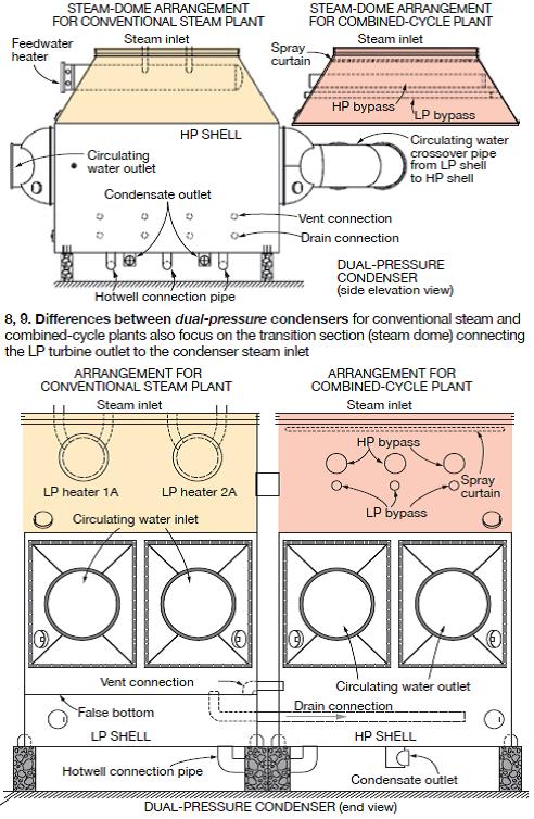
There are substantial differences in design between condensers for conventional steam plants and ones for combined cycles. These differences should be understood to guide appropriate modifications before repowering steam stations with gas turbines, stressed Dr Ranga Nadig of Maarky Thermal Systems Inc, Cherry Hill, NJ, at the 2013 ASME Power Conference. Nadig’s paper, “Considerations in Converting a Dual-Shell or Dual-Pressure Coal-Fired Plant Condenser into a Combined-Cycle Plant Condenser” (POWER2013-98062), can be accessed in the meeting proceedings.
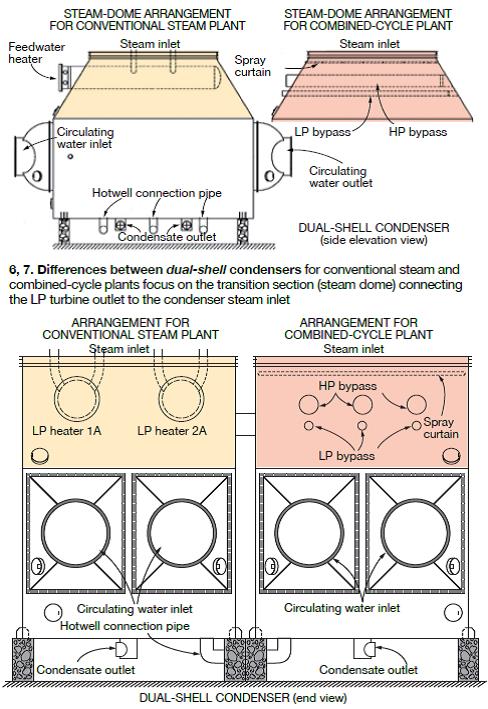
Steam surface condensers for large generating plants usually are of the dual-shell or dual-pressure type. Recall that:
- A dual-shell unit consists of two identical shells operating at the same pressure; the hotwells and the steam domes of the two shells are connected (Figs 6, 7).
- In a dual-pressure condenser, the two shells operate at different pressures (Figs 8, 9). Circulating water enters the LP shell and, upon exiting, enters the HP shell. Cycle efficiency is improved by partially heating the condensate from the LP shell in the hotwell of the HP shell.
 |
 |
Condensers for large steam plants generally are equipped with feedwater heaters in the condenser neck, extraction piping, an external flash tank, and a large number of vents and drains. By contrast, combined-cycle condensers do not have integral feedwater heaters or extraction piping. Plus, they have no external flash tank and the number of vents and drains is minimal.
Although their operating principles are the same, Nadig told attendees there are substantial differences in the design and construction of condensers for conventional steam plants and combined cycles—including these:
- Combined-cycle plants have higher turbine exhaust-steam flow rates and often are required to operate for a short, or extended period in bypass mode.
- Coal-fired plants have pressurized deaerators to remove oxygen from condensate; in combined cycles, condensate is deaerated in the condenser.
- Combined cycles in cogeneration service dispatch a portion of turbine extraction steam for heating purposes. In such arrangements, an equivalent quantity of makeup water is introduced and deaerated in the condenser.
- In conventional steam plants, vents and drains often are admitted to the condenser via a flash tank. In combined cycles, the vents and drains often discharge directly to the condenser.
Design features common to dual-shell, dual-pressure condensers
Heat-transfer surface, support-plate spacing. The heat-transfer surface in the existing condenser should be sufficient to meet the combined cycle’s performance requirements; the existing support-plate spacing should be less than that needed for the repurposed turbine’s exhaust-steam flow rate. Because the combined-cycle condenser will be operating in bypass mode periodically, it is prudent to increase the wall thickness of tubes in the impingement zone.
If possible, Nadig said, the top two rows of tubes in the impingement zone should be replaced by two rows of 14-BWG carbon-steel dummy tubes to help prevent tube failures and protect impingement-zone tubes from wear and tear during normal and bypass operation.
Feedwater heaters in the condenser neck are removed when repurposing a conventional steam-plant condenser for a combined cycle. The presenter stressed exercising care when extracting the heaters and their supports, to protect condenser internals (especially the tubes) against damage. Openings in the steam-dome plate to accommodate the feedwater heaters must be closed with an adequately stiffened cover plate, he said, to withstand the shell-side design pressure.
Also, extraction piping from the steam turbine must be removed and the open ends capped. Best practices: (1) Install drain connections on the end caps and rout them to the condenser hotwell. (2) Stiffen the ends of the extraction piping.
In a combined-cycle plant, the condenser must accept steam from the HRSG pressure-reducing desuperheating (PRD) valve when the steam turbine is not in operation. This typically is referred to as bypass operation and requires installation of bypass headers—HP, IP, and LP—in the steam dome (refer again to Figs 6, 8). Each HRSG is equipped with dedicated HP, IP, and LP bypass headers. To avoid excessive pressure variations, the bypass steam from each boiler must be split evenly between the condenser shells.
Bypass headers from multiple HRSGs can be manifolded into a single header, but this could cause pressure variations in the header during periods of partial bypass flow. To assure proper distribution of steam in the condenser, locate the centerline of the bypass header at least 6 ft above the topmost tubes.
Extend bypass headers along the length of the tubes to distribute steam evenly along the entire tube bundle. Nadig recommended that the bypass header be equipped with the smallest possible orifices—typically 0.25 in. diameter. They should be installed along the length of the header and oriented sideways, he added, so flow is not directed at turbine internals or the condenser tubes.
Nadig also suggested that the bypass admission design be in accordance with EPRI Report CS2251, “Recommended Guidelines for the Admission of High-Energy Fluids to Steam Surface Condensers,” with appropriate corrections. He recommended sloping the bypass header along the length of the tubes and installing a drain connection with an impingement plate at the far end of the header to assure positive drainage.
The PRD valve should be designed and operated to assure that only dry steam is sent to the condenser, the speaker continued, and be sure the valve fails in the closed position. Nadig stressed carefully monitoring the temperature of bypass steam admitted to the condenser and establishing alarm settings for lower- and upper-bound temperatures. Proper control of steam temperature is critical to trouble-free bypass operation.
Caution: During bypass operation, some high-temperature steam may migrate into the turbine exhaust. A spray curtain can protect turbine internals and the expansion joint against excessive temperature. Installing the curtain just below the expansion joint is recommended. The nozzles should spray cold condensate in a fine mist covering the entire cross section of the turbine exhaust.
Vents, drains, flash tank. When retrofitting your steam-plant condenser for combined-cycle service, blank off discontinued vents and drains. Also, if a flash tank is installed, review its design with the new arrangement of vents and drains to assure its suitability for combined-cycle application. Nadig recommended that your analysis consider, among other things, the operating pressure in the flash tank, the loop-seal design for the condensate drain to the condenser hotwell, and the orifice-plate design for the condenser vent.
Design features particular to dual-pressure condensers
A false hotwell bottom is installed in the LP shell about 18 to 24 in. below the lower-most tube. It is not designed to handle the shell-side design pressure or the loads encountered during a shell-side hydro. The welds between the false bottom and the shell walls, and those between the false bottom and the hotwell support pipes, must be carefully examined for cracks. Failure to find and repair cracks can lead to performance loss as leaks tend to equalize the pressure between the two shells.
After completing the mods necessary to repurpose an existing condenser for combined-cycle service, conduct a shell-side hydro. Because the false bottom is not designed to withstand the pressures associated with a hydro, install manways to permit the free flow of water in the spaces above and below the false bottom.
Draining condensate from the LP to HP shells. Condensate collected in the space above the false bottom in the LP shell is drained into the hotwell of the HP shell, as shown in Fig 9. Because the LP shell operates at a lower pressure than the HP shell, provide sufficient head in the drain pipe to permit positive flow under all operating conditions.
Insufficient head can cause condensate to back up in the LP shell above the false bottom, submerging tubes and leading to an increase in LP-shell pressure. Condensate from the LP shell should be drained into the HP shell at a minimum of three to four locations along the length of the shell.
Venting considerations. Vent the steam space below the false bottom in the LP shell to the HP shell at a minimum of three to four locations along the length of the shell (refer again to Fig 9). Insufficient venting can lead to problems in hotwell level control because of the difference in levels between the hotwells for the LP and HP shells.
Circ-water crossover piping. When calculating the overall tube-side pressure drop for dual-pressure condensers, be sure to include the delta p in the crossover piping between the LP and HP shells, in addition to the tube-side pressure drops for each shell. It is important that the design of the circ-water crossover piping be evaluated to ensure satisfactory performance in combined-cycle service.
Design features particular to dual-shell condensers
A dual-shell condenser is much simpler in design compared to a dual-pressure condenser. As mentioned earlier, the former consists of two identical shells connected in the steam-dome and hotwell locations. An important design point is to be sure the ducts connecting the two steam domes are large enough to equalize the pressure in the two shells under all operating conditions. Special attention should be given to the removal of debris from the piping connecting the two hotwells.
Benefits of integrating solar towers with combined cycles
Countries committed to reducing CO2 emissions may incentivize utility and industrial power producers to build renewable generation assets characterized by low carbon intensity. With operators looking for the most cost-effective power-generation option, the integration of renewable energy sources with existing assets, or in new hybrid plants, may be appealing.
Renewable energy technologies, such as concentrating solar power (CSP), have made significant progress in the last decade with regard to efficiency and cost. However, in Australia and some other countries, when making investment decisions without including external costs for fossil fuels or government incentives for renewable electricity, the current economic climate favors natural-gas-fired simple- and combined-cycle plants over CSP installations.
To lower the specific investment cost of CSP and prepare for the expected increase in natural-gas prices, some Australian engineers see value in retrofitting existing gas-turbine plants with concentrating solar power as well as in designing plants from the ground up with a CSP component. This would create both environmental benefits—such as a reduction in carbon intensity—and economic benefits, including less-expensive CSP installations and renewable energy certificates.
An area of current interest is the retrofit of solar towers to reduce cost and allow independent operation of the combined-cycle and CSP components. Most existing integrated solar/combined cycle (ISCC) plants use parabolic trough systems with thermal oil to boost HRSG steam production. This is a well-established concept, acknowledged the authors of “ISCC Plants Using Solar Towers with Thermal Storage to Increase Plant Performance,” presented at the ASME 2013 Power Conference (POWER2013-98121), but it limits the solar contribution and requires both plants to operate simultaneously.
Authors of the paper are the following: Juergen H Peterseim, Univ of Technology Sidney; Dr Amir Tadros, Aurecon Australia; Prof Udo Hellwig, ERK Eckrohrkesse GmbH; and Prof Stuart White, Univ of Technology Sidney.
Depending on the load profile, the ISCC could operate with or without storage capability. Thermal storage would be valuable to provide solar-generated electricity during periods of peak demand, such as the early evening hours. However, today’s high cost for thermal storage—about $90/kWh (thermal) makes it difficult to justify this investment without a premium on power dispatchability.
Australia and suitability
ISCC seems to be a suitable technology for reducing the carbon intensity of Australia’s power-generation portfolio. The country has vast natural-gas reserves and abundant locations with excellent direct normal irradiance (DNI). But gas prices are expected to increase significantly if new LNG facilities come online over the next several years as anticipated. The CSP component also would benefit from current and expected increases in electricity prices.
From an economic perspective, ideal locations for ISCC facilities in Australia are remote load centers—such as the mining areas in the West. Electricity prices are higher there than along the East Coast, where a grid distributes large quantities of low-cost electricity from coal-fired powerplants.
Of particular interest are locations where GTs already are installed, because conversion costs would be comparatively low. Several operating plants known to the authors would qualify for ISCC conversion. They also recommended investigating the ISCC option for plants in the planning stage. Where the DNI is sufficiently high, the developer should at least reserve area for a future plant conversion.
Typically, an average daily DNI of more than 20MJ/m2 is required for a standalone CSP plant. However, the cost-reduction benefits of ISCC facilities made possible by the joint use of plant equipment (such as steam turbine and condenser) suggests that areas with a DNI above 17MJ/m2 should be considered as well.
ISCC plants in operation
Several ISCC plants are now operating—including ones in the US, Egypt, and Morocco. The largest, rated 75 MW, is the Martin Next Generation Plant in Florida. The authors said that all ISCC plants in service at the time of the ASME meeting relied on the mature parabolic trough technology, with thermal oil providing saturated or slightly superheated steam to the heat- recovery steam generator. In the HRSG, superheat is added to match steam-turbine requirements. This concept is well proven in several ISCC plants; the solar contribution typically is less than 15% of the total plant capacity.
The use of parabolic-trough technology with thermal oil limits steam temperatures to less than about 735F because the heat-transfer fluid degrades very quickly above 750F. To increase the steam enthalpy provided to the host plant, other working fluids, such as molten salts, must be used. A 5-MW prototype parabolic-trough plant using molten salt and thermal storage was retrofitted to the Priolo Gargallo combined-cycle plant in Italy; its steam temperature is nearly 1000F.
Solar-tower ISCC
With more solar-tower plants operating and under construction worldwide (including Gemasolar in Spain, and Ivanpah and Crescent Dunes in the US), the technology becomes increasingly mature and bankable. Significantly higher steam conditions (more than 1000F and 1600 psig) compared to parabolic troughs with thermal oil, facilitate CSP’s integration into the CCGT’s high temperature/pressure steam cycle.
The benefits of all ISCC plants are cost savings through the joint use of equipment—such as steam turbine, condenser, and feedwater system. However, solar-tower ISCCs have the potential additional benefit of sharing building infrastructure—for example, the stack could be modified to support the solar receiver.
The thermal-storage capability of solar-tower plants cited in the literature extends up to about 15 hours of full-load operation, twice that for a parabolic-trough system. Implementing thermal storage has the potential to maximize the CSP contribution but it strongly depends on the financial value of energy dispatchability. CCJ