
By Clyde V Maughan, Maughan Generator Consultants
The generation sector of the electric-power industry has undergone many changes in its 100+ year history, both in technologies and in government influences. Relative to generator technology, for example, the evolution of cooling methods has included (1) open-flow air cooling, (2) closed-flow air with coolers, (3) hydrogen-atmosphere cooling, and (4) direct hydrogen and/or water cooling.
Because power generation is resource-intensive and covers large geographic areas, government involvement in the industry was inevitable. Nevertheless, for many years the market was controlled, to some extent, by the original equipment manufacturers. Profit margins were generous and generator OEMs had the resources to make quantum leaps in rating and design sophistication while generally producing a quality product.
In the early 1970s, government began forcing the industry in the direction of increasing competition. The cost pressures associated with this transition have had significant negative impacts regarding generators, including: (1) Increasingly lower quality of new machines and (2) increasingly lower capability of technical support for addressing the inevitably high rates of in-service problems.
Quality has suffered as new designs pushed duties to higher and uncharted levels and as these designs incorporated less costly materials and procedures to allow faster manufacturing. Technical capability has suffered as OEMs have greatly reduced the number of engineers in their organizations and as institutional knowledge has been lost to retirements.
The industry impact associated with quality issues has been profound, and appears increasingly so. The goal of this article, which is based in part on a presentation by the author at the 2013 Conference of the Combined Cycle Users Group, is to help owner/operators better understand some of the major technical and business issues concerning generators today.
Premature failures
Historically, utility-size generators were made with considerable margin in load capability. But with powerful computers and increased competition providing both the capability and motivation, the latest generator designs have increased mechanical, electrical, and thermal duties to the point where little margin remains.
Generators rarely exceed specification parameters today. The result is a fleet of machines that increasingly requires major maintenance long before the historic target of 30 years for stator windings and 20 years for field windings. Examples are cited below.
Stator endwinding vibration has been an ongoing issue for large generators. Problems have been exacerbated as engineers designed to accommodate higher vibration driving forces while simplifying support systems. A case in point is the elimination of series blocking on the endwinding in Fig 1, which caused the broken bar in the photo. Local endwinding resonance resulted in the failure shown in Fig 2.
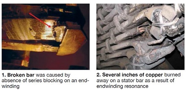
Protection against such failures probably is best obtained by being sure a thorough bump test is performed on new and reworked windings. Resonant values should be outside the 115-140-Hz range (for 60-Hz generators).
Stator-bar slot vibration. Large, indirectly cooled generators typically have many stator slots and tall, narrow bars. This design approach maximizes the area for transferring heat through the groundwall insulation. But it also may allow the tall, narrow bar to vibrate sideways in the slot, probably driven by core vibration. Such vibration causes vibration sparking, a fast-acting destructive phenomenon (Figs 3, 4).
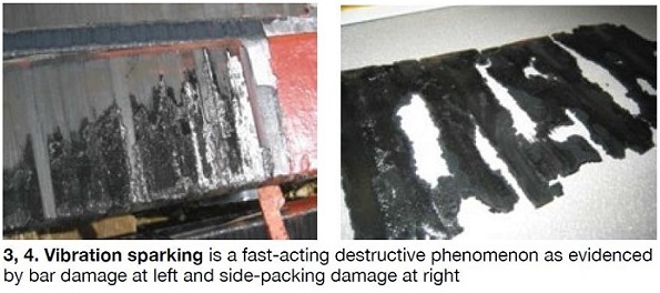
Designers believed side filler would prevent side vibration. However, packing of incremental thickness cannot fully fill a continuously varying space, and vibration can occur. If deterioration is significant, corrective action probably requires a rewind to remove the fatally degraded bars and allow installation of side pressure springs.
Dry endwinding support ties. The integrity of endwinding support systems on some generator designs relies heavily on bonding of the ties to the support structure, connection rings, and stator bars. Some OEMs have used a wet tie to make this bond as strong as possible. For cost and simplification reasons, a changeover was made to dry ties, which have not performed well and have led to numerous problems (Figs 5, 6).
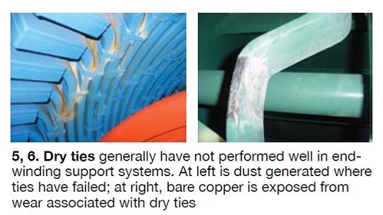
Note that wet means the glass for making the tie is drawn through a resin of high bonding strength as the tie is being made; dry means the glass is pre-impregnated with a resin that is dried, slightly cured, to allow for ease of application.
Experience indicates that after a few years of operation with dry ties, heavy insulation wear may be in evidence at several locations, leaving significant exposure to an extremely damaging phase-to-phase fault. The scope of repair depends on the amount of damage. If the insulation is intact, simply replacing the dry ties with wet ties may be all that’s necessary. Were a phase-to-phase fault to occur, stator and field rewinds along with extensive cleaning are likely to be required, and in worst case, replacement of the generator might be necessary.
To learn more about dry ties and the problems associated with them, read Generator inspection first step in avoiding failures attributed to dry stator-winding ties.
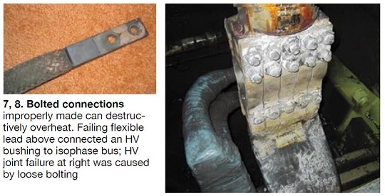
Bolted connections have been used in the electric-power industry since its infancy. Safely carrying current through a bolted joint requires two primary conditions: clean non-oxidized surfaces and high local contact pressure. Meeting these two conditions for high-current applications is something of an art, one dependent upon passing known skills down from generation to generation of skilled personnel. If this knowledge is lost, the result can be joints that begin to destructively overheat (Fig 7).
A joint similar to one shown in Fig 8 was made up with bolts of stainless steel, which has a propensity to gall. In this case, the nut-to-bolt galling absorbed the torque of the wrench and left some bolts loose, but with apparent proper torque. The result was joint failure, massive arcing, extensive contamination, and a stator and field rewind—plus weeks of frame, cooler, and core cleaning.
Prevention of bolted-joint problems involves being certain of the following:
- Connecting surfaces are properly plated.
- Surfaces are clean.
- Selected torque values are correct.
- The nut/bolt torque is not influenced by galling or other friction conditions.
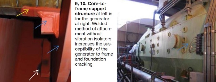
Core/frame structure. On 2-pole generators, the core must be isolated from the frame by a flexible attachment. Otherwise the inevitable vibration of the core outside diameter, typically about 2 mils, may transmit intolerable vibration and noise to the frame. While the term vibration is commonly used, the condition actually is deformation of the core caused by the magnetic pull of the field flux on the core.
The core-to-frame support structure for the Fig 10 generator is shown in Fig 9. The core (yellow arrow) is attached directly to the keybar/bore ring fabricated structure (blue arrows), which is welded directly to the frame outer wrapper (white arrow). This configuration eliminates the cost of isolation components, but leaves the generator vulnerable to noise levels approaching 116 dB(A), and the prospects of possible frame and foundation cracking. Operation may be acceptable if the noise levels can be tolerated and frame and/or foundation cracking do not occur. Otherwise, this condition may not be correctable without stator (or generator) replacement.
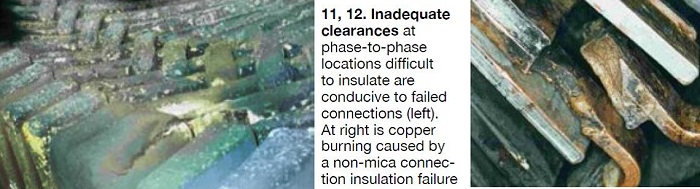
Series and phase connection insulation. These connections are difficult to insulate with mica tapes. Thus for many years, there has been widespread use of a much faster and lower-cost insulating method: A non-conducting box filled with non-mica potting compound.
This is perfectly adequate at the low voltage difference between series connections. But if air- gap clearances are less than about 3/8 in. at phase-to-phase locations, partial discharge can occur. Figs 11 and 12 were photographed at one such line-to-line phase break. Designers now typically use potting compound on the series connections, but insulate the phase connections with mica tapes.
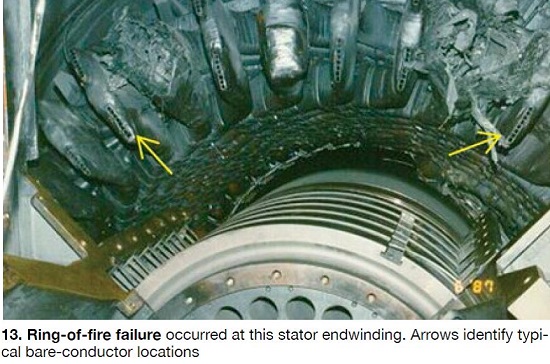
However, it is impossible to fully insulate the connections on direct-gas-cooled stator windings—because access for gas flow must be permitted. Numerous massive winding “ring-of-fire” failures have occurred on machines with heavily contaminated insulating surfaces and air gaps. Contamination that led to the failure in Fig 13 was the result of an arc from a broken bar or connection. For stators manufactured with bared conductor, your first line of defense against failure, and possibly the only one, is to assure no gross contamination occurs.
Global vacuum pressure impregnation. VPI of individual stator bars with asphalt began a century ago. Stator-bar VPI with thermoset resins started in about 1949 and has been used successfully to make high-quality stator windings since.
In the 1960s, global VPI was identified as a fast and inexpensive method of making a stator. The process involves putting the entire stator, wound with “dry” coil insulation, in a large VPI tank, where it is impregnated in a single operation. GVPI was first used on motors and small generators. In the mid-1970s it became popular with some OEMs for making large generators—even ones rated more than 400 MVA. But these windings have been subject to some maintenance issues, including the following:
- Slot partial discharge and possibly vibration sparking, which seem to be related to a slip plane between bars and core.
- Difficulties in performing a rewind, which are related to the VPI process bonding stator bars into the slots. It is difficult-to-impossible, and time-consuming, to remove the winding to allow a rewind. Where a rewind is performed, the process is slow and the core is vulnerable to damage. On a GVPI generator, for quality and outage time considerations, stator replacement may be preferable to the rewind option.
Notwithstanding these limitations, because of the major advantages to GVPI, this process will remain popular for large generators.
Step-down at end of co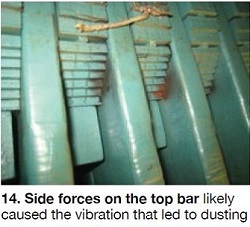 re. High design uprate of modern generators involves greater step-down of the iron at the ends of the core. Because this puts the top of the top bar above the core iron, there is high air-gap flux cutting the copper strands at the top of the top bar and a significant sideways electromagnetic force (EMF) on the top bar.
Apparently, this causes sideways vibration of the bars at the end of the core (Fig 14); however, this condition may be relatively benign, and placing side pressure springs on the side of the bar to apply force in the same direction as the EMF may stop the vibration.
But there is another, perhaps more important, concern. Back into the slot a foot or so from the core end, the top of the top bar is deep in the slot. At that depth, the air gap flux has essentially all transferred into the iron (Fig 15). No air gap flux is cutting the copper and thus there is no side EMF on the bar.
But in these new designs, the top of the top bar is above the core tooth iron (refer back to Fig 14). If the bar is shallow in the slot, as it is in hydro generators, there is air-gap flux cutting the top strands of the top bar and you can get the condition shown in Fig 16.
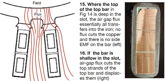
Thus there becomes the worry that this strand-movement phenomenon may occur on modern 2-pole stators—perhaps a greater worry because the top of the bar is completely out of the top of the slot and exposed to full (reduced) air gap flux and corresponding EMF. End-of-slot concerns are relatively new, and assistance of the OEM should be obtained for assessing the scope of possible problems and corrective options.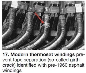
Tape migration on stator bars. This was a highly destructive deterioration mechanism on asphalt windings for pre-1960 generators rated more than about 40 MW (Fig 17). This condition was eliminated by use of thermoset windings. But the problem has recurred on post-1970 small (less than 20 MW) coil-wound generators that were made with an inappropriate asphalt material (Fig 18). The generator shown had been in service 20 years. The winding failed during a power factor test at line-to-neutral voltage. Repair of such a failure likely would involve a stator rewind.
High electrical stress on stator windings. Historically, the electrical stress across the stator-bar groundwall has increased very slowly over time. This is because electrical duty increases at about a ninth power of stress—volts/mil (vpm). On asphalt/mica windings, design stress was about 45 vpm.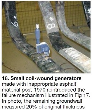
For the polyester/mica systems introduced in the 1950s, stress was increased to around 54 vpm. With the introduction of epoxy/mica systems in the 1960s, stress initially went into the 60-65-vpm range; now designs above 80 vpm are being produced. Note that the increase from 65 to 80 vpm is large—650% (divide 80 by 65 and raise the result to the ninth power).
To date, generators rarely have failed because of electrical duty, but expect that as stress levels increase, pure electrical failures will appear.
There is another condition on generators that is less benign. Specifically, these increased stresses are no doubt related to the increase of partial discharge (PD) activity being seen on modern air-cooled generators (Fig 19). It is unlikely that PD activity will fail the winding, even after many years of service. But ozone generation can be high, and this alone may force a stator rewind.
Rotor problems
Problems with field windings—such as grounds, distortion of and shorts in turns and coils, migration of coils and slot and tur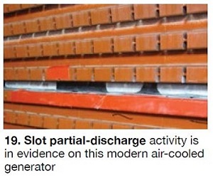 n insulation, as well as broken turns and connections—continue to occur frequently, as they have for years. Interestingly, design margins in fields have not been impacted as greatly as those for stators, largely because fields never were engineered with much margin. But also, since copper’s mechanical properties are inherently marginal, there has not been much opportunity for cost reduction and increase in duty on fields.
The design temperature of fields fortunately has been slow to evolve upward. High-temperature insulation materials are available, but copper has poor mechanical properties, even at room temperature—properties that degrade rapidly above about 265F.
Direct cooling has been the best uprate tool for fields: It reduces the average copper temperature, as well as hot-spot temperatures. However, direct cooling can bring problems when contaminated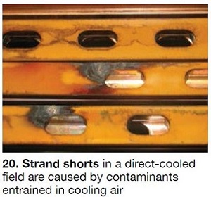 atmospheres are allowed to foul generator internals. Turn shorts sometimes are associated with cleanliness issues (Fig 20).
Complex and mechanically weak gas-entry locations are another challenge presented by direct cooling. Brazing in those areas can make turns vulnerable to cracking of the copper (Fig 21) and winding failure.
Historically, field forgings generally have not been associated with catastrophic failures; less so today, because of improvements in the quality and consistency of forgings over the years. The primary remaining quality/cost issue on forgings remains the many 18/5 (18% manganese, 5% chromium) retaining rings still in service.
Recall that this alloy is vulnerable to stress corrosion in the presence of moisture; several have failed catastrophically in service. For generators still operating with 18/5 rings, it is vital that the rings not be exposed to water—in particular on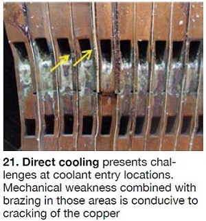 the inside diameters of the rings.
About 25 years ago the replacement 18/18 alloy was developed for retaining rings. Although not subject to stress corrosion, it can crack in the presence of severe conditions—for example, an extremely aggressive atmosphere, torsional resonance, etc. One OEM recommends a ring inspection every 12 years; required tests can be conducted without removing the field.
The talent conundrum
Cost pressure undoubtedly is the primary cause of failures in modern generators. It has contributed to a reduction in design margin and has seriously reduced the capabilities of OEM design, manufacturing, and service organizations.
Generator issues also can be traced to the inability to effectively transfer lessons learned/best practices from experienced design and service engineers to new hires. Much of the knowledge on how to build and repair a generator is, in a real sense, art. Failure to pass on this know-how in an organized and effective manner repeatedly has led to the “reinvention” of old problems. The sections above having to do with dry ties and improperly made-up bolted joints clearly illustrate the point.
Given existing industry conditions, it simply is not possible to maintain the numbers of skilled engineers and technicians required to design, manufacture, and maintain generators to satisfy customer expectations. Budgets aside, there are other contributors to the loss of talent. Three come to mind:
- Power generation is no longer a “glamor” business for attracting the top talent demanded for design and manufacture of the complex generator.
- Today’s design engineers are spread thin and it is difficult for an individual to become highly skilled in any one discipline.
- The advent of computer-aided design has reduced the “feel” for the machine that came from using a hand calculator and slide rule.
Impact of an inadequate RCA
Historically, diagnosis of new and complex generator failures was done by OEM factory engineers because accurate problem assessments can be aided significantly by a technical education background and by generator design experience. The staffing reductions noted earlier translate to fewer engineers with diagnostics capabilities being available for problem investigation and root-cause analysis.
RCAs of generator failures can be difficult. Consider the following:
- Generators are mechanically complex and generator operational theory is challenging. While the design and operation of most plant equipment are somewhat intuitively obvious to an experienced engineer, there is little about a generator that is obvious to even those with the best intuition.
- Generators can fail in many ways. Most plant personnel have heard an OEM engineer say, “We haven’t had this kind of failure before.” This typically is greeted with skepticism. However, there are so many ways a generator can fail, this comment may be accurate on occasion.
- Powerplant O&M personnel typically are much more familiar with gas and steam turbines, and I&C, than with generators and HV equipment.
- Generator failures often involve major destruction to the failure location because of burning and arcing damage. This may require that the root cause of failure be decided by implication.
- Even with the best generator monitoring instrumentation available today, plant records often shed little light on the failure root cause.
Misdiagnosis of the root cause of a generator failure can be exceptionally costly (tens of millions of dollars and perhaps in the 100s with loss of generation costs included), while leaving the machine vulnerable to a repeat of the same failure. Here are some recent experiences:
- A ring-of-fire stator winding failure on a 900-MW water-cooled winding was incorrectly attributed to the internal piping arrangement. Had the correct design error not been identified by further consultation, repeat of the massive stator winding failure would have been inevitable (refer back to Fig 13).
- A stator winding failure on a 200-MW generator was incorrectly attributed to “lightning.” Corrective action taken was based on this misdiagnosis. The unit failed again several months later at the same location for the same reason—partial discharge (refer back to Figs 11, 12).
- On a 250-MW generator, dust accumulation on a core end-package was believed caused by minor stator-bar vibration and no corrective action was taken. The root of the problem actually was local core looseness. A few weeks after return to service, the winding failed to ground: Stator-bar insulation wear was caused by pieces liberated from core laminations.
- Core discoloration at the location of stator winding failure was judged “insignificant” after inspection and a deficient ElCid test. This 80-MW stator was rewound without correcting the core-iron condition. Shortly after return to service, the new replacement winding failed: Core iron melted in the same location.
- An asphalt stator winding was incorrectly diagnosed as having “destructive migration of the groundwall” (refer back to Fig 17). An inexperienced OEM engineer and an inexperienced independent consultant each recommended immediate stator rewind to avoid “catastrophic service failure.” Their recommendations were vacated by a more experienced engineer, and this stator winding continues to operate safely many years later.
Concluding observations
There are no easy answers to the dilemma of marginal equipment and inexperienced service personnel. Generally, a deficient design does not leave margin for modification to a lower-duty design, and there seems no ready solution to the problems relating to technical personnel limitations. Apparently, the current difficulties and challenges will remain until such time as owners transition from a first-cost to a lifecycle-cost mentality regarding equipment purchases.
Until that utopian condition arrives, generating-plant personnel might consider following the four initiatives below for dealing with generator challenges:
1. Monitor your generator with state-of-the-art instrumentation.
2. Maintain monitoring equipment in good operating condition.
3. Record and retain all information gathered by diagnostic instrumentation.
4. Should your generator suffer a failure, assure that the investigation and RCA are thorough and the information provided by the OEM and/or independent consultant is both plausible and reasonable. If not, quickly enlist additional technical support to prevent the loss of information and valuable time.
Consider that a “we don’t know” conclusion by the investigative team is acceptable when the cause of the failure cannot be determined with a high degree of accuracy. As the bullet points immediately above attest, inaccurate conclusions can be very costly. CCJ
 Clyde V Maughan is president of Maughan Generator Consultants, Schenectady, NY. He has more than 60 years of experience in the design, manufacture, inspection, failure root-cause diagnostics, and repair of generators rated up to 1400 MW from the leading suppliers in the US, Europe, and Japan. Maughan has been in private practice for the last 25 years. He spent the first 36 years of his professional career with General Electric Co. More articles and resources can be accessed at www.ccj-online.com/maughan.