
The largest F-class gas-turbine fleet worldwide is the GE 7F. The number of engines in service alone makes meetings of the independent 7F Users Group important for owner/operators to attend. Given the 250 or more user attendees expected, you’ll hear about virtually every problem in the fleet firsthand at the meeting’s vibrant open forums.
Perhaps you already knew this.
But what may make your next the most important 7F meeting ever is the information learned in group discussions and private hallway conversations could prove invaluable for helping your plant/company navigate the wrenching industry changes ahead.
Consider the following:
- Industry scuttlebutt is that the purchase of Alstom by GE probably will receive final approvals this summer. How might owner/operators planning an engine purchase be impacted by the virtual elimination of one of the four major OEMs involved in the manufacture of large frame gas turbines?
- Will purchase of a late model Frame 7 (7F.04 or 7F.05) dictate an LTSA that could restrict or eliminate the flexibility you now have regarding third-party parts and services?
- At least equally important: How would you learn anything about the new models if you don’t come to Denver and renew your relationships with fellow 7F users?
- What might be the impact on your outage activities if PSM, an Alstom company, no longer is able to support the 7F fleet with parts and/or services?
The questions you can think of probably would fill a couple of pages in a large notebook. Bring them, participate in the discussion, and get the answers needed to keep your plant operating profitably and at high reliability. The following summary of last year’s meeting notes compiled by the editors helps clarify the value of participation in the 7F Users Group.
Audience polling
Last year, the 7F Users became the first independent user group serving gas-turbine owner/operators to integrate an audience response system into its meeting—and with great success. Every user attendee is loaned a small wireless keypad for voting when he or she registers; keypads must be returned at the end of the meeting.
A member of the steering committee keys the questions, most generated spontaneously by speakers or members of the audience, into a PowerPoint slide and posts it on the screen for a vote. Example: One of the questions asked by the meeting chairman during his opening remarks was “How many first timers are attending?” A few seconds later, the following appeared on the screen: First timer? Press 1 for “yes,” Press 2 for “no.” In another few seconds you learned that 228 attendees had voted and 42% were first timers.
It didn’t take more than the first series of questions to get virtually everyone involved. The system’s value is exceptional. Example: A user weighing a few options for an operating procedure can poll the group in a heartbeat asking colleagues to share their experiences (yes or no) with option 1, 2, and/or 3.
In addition to the statistical data, the polling system captures each respondent’s unique 7F ID number as part of the reply, allowing the person asking the question to follow up during the meeting, or later, with one or more colleagues.
Use of the polling system brought to light the following demographics of the 2014 7F User Group audience:
- Work experience with F-class GTs: 49%, more than 10 years; 22%, 5-10 years; 15%, 2-5 years; 14%, less than two years.
- Job function: technician (electrical and/or mechanical), 6%; technician (operations), 8%; engineer, 35%; management (corporate), 19%; plant manager, 8%; operations manager, 9%; maintenance manager, 15%.
- Job prior to GTs: fossil-fired powerplant, 41%; nuclear powerplant, 5%; OEM, 9%; pulp and paper, 6%; military, 13%; other, 27%.
- Have performed the following compressor upgrades: Package 1, 3%; Package 2, 15%; Package 3, 31%; Package 4, 14%; Package 5, 11%; non-GE solution, 11%; don’t know, 15%.
- Upgrade 7FA.03 to 7FA.04: 11% have; 15% might.
- Maintenance performed by: OEM (transactional), 10%; OEM (LTSA), 54%; third-party (transactional), 13%; third-party (LTSA), 6%; self-perform, 17%.
- Parts repaired by OEM, 66%; third party, 34%.
- Compressor inlet cooling: evap cooler, 55%; fogging, 19%; chiller, 26%.
- Inlet filters: cellulose, 18%; synthetic, 48%; hybrid, 11%; HEPA, 23%.
- Use prefilters: 56%, yes; 44%, no.
- Online water wash: daily, 39%; weekly, 7%; monthly, 2%; quarterly, 6%; twice annually, 3%; annually, 2%; other, 39%.
- Online water wash duration: 5 min, 13%; 10 min, 8%; 15 min, 23%; 30 min, 8%; longer than 30 min, 2%; do not online water wash, 46%.
- Off-line water wash frequency: monthly, 2%; quarterly, 18%, twice annually, 53%; annually, 14%; other, 13%.
Compressor issues
Compressors get considerable air time at 7F Users Group meetings. It seems there’s always something to talk about: If it’s not R0, then it’s probably S0-S4, or perhaps R13-R16, or R17. On the first day of the 2014 conference, Chris Johnston, PSM’s Director of Airfoils Engineering R&D, spent half an hour explaining reliability improvements his company’s engineers have designed into the replacement parts it offers for this machine. The following day, several user case histories and an open discussion period added up to another two hours on compressors. On Day Four, the OEM had a 45-min presentation.
Here are some of the takeaways from the user presentations and discussion:
Corrosion pitting. The first speaker reported on corrosion pitting in four gas-turbine compressors, located at the same site, which began commercial service in 2000. He said excessive pitting was identified in 2001 and attributed to carryover of poor-quality water (containing chlorides) from the evaporative coolers. A reverse-osmosis system was installed about two years after COD to pretreat the raw surface water; revised operating procedures eliminated carryover.
However, the damage done in the first two years was irreversible and, despite the use of quality water for the next 10, an R1 blade in Unit A liberated because of suction-side corrosion at the root of the airfoil. At the time, the unflared compressor had accumulated only about 1100 starts and 5500 operating hours.
In May 2013, the plant owner had the OEM conduct “enhanced” borescope inspections (100% dye penetrant and UT) on Units B, C, and D. A definitive assessment was not possible because the risk factor associated with pitting could not be defined. No cracks were identified in any of the airfoils, just elevated levels of corrosion. Had cracking been found, the affected units would have been removed from service immediately.
The OEM’s recommendation was to re-inspect the units after the run season. The speaker mentioned that GE was selected for the inspection because corrective action would be based on those results and the OEM wouldn’t make decisions based on information from another company’s inspection.
A detailed analysis of corrosion pitting was conducted on Unit B during a scheduled outage. It was carefully planned out, with specific areas of specific blades selected for inspection in the first three compressor stages. Fluorescent penetration inspection and dental molds were used with the goal of identifying the “showstopper” as soon as possible—if one existed.
What the inspection team found were flaws identical to those that caused the Unit A failure, but larger. Also found were flaws in non-repairable areas of some airfoils, making the business decision to buy a replacement rotor relatively easy, especially considering time constraints.
For the remaining two units, the following O&M plan was adopted:
- Inspect the suction side of R1 blade roots for cracking.
- If no cracks are detected, clear the units to run a specified number of starts prior to re-inspection.
This process would allow time to schedule unit outages to re-blade the rotors.
Keep in mind that once pitting begins, it’s only a matter of time before the blades will require replacement. Allowing a machine to operate with severe pitting seems analogous to Russian roulette: The decision to run essentially is based on qualitative information. You hope there’s no bullet in the chamber and the next time the machine is started is not the last time.
The speaker strongly advised his colleagues in the audience to maintain inlet filter houses, and water quality for evaporative cooling and compressor washing systems in top condition right from commercial start; also, to maintain tight control over droplet size of any water entering the compressor from fogging and washing systems. The best way to avoid pitting and erosion of compressor blades, he said, is not to allow it to happen.
Blending of 17th-stage discs. The next user presentation concerned cracking of the 17th-stage compressor wheel and experience with poor quality rework. The CliffsNotes version of the industry’s experience according to this owner/operator: lots of cracking and blending, lots of replacement wheels, lots of extended outages, cracks on both the forward and aft faces of the wheels, cracking observed after only about 1000 cycles, cracks up to 200 mils deep (OEM blend limit: 100 mils), in-situ blending experience with and without blades, some owners leaving cracks.
The speaker reported on his company’s experience with a new precision-engineered blending process from AccTTech LLC said to reduce critical wheel stresses by more than 20%. Inspection revealed that most of the 60 slots in the disc repaired had cracks; maximum depth was 95 mils. The speaker said AccTTech’s engineered tooling for uniform machining and polishing removed all cracks in two shifts, a fact verified by 100% NDE. Longer disc life is expected because of the lower-stress profile created. Get a progress report at this year’s meeting.
Upgrade options. A user conducted a short review of the OEM’s upgrade options for both flared and unflared compressors to help colleagues better understand what’s available to deal with R0 erosion, R17 wheel cracking, stator twisting, and other issues.
Included in the presentation was a review of applicable Technical Information Letters (TIL) and the different requirements for original parts and enhanced parts. Example: TIL 1603, which concerns R0 erosion and water ingestion recommendations, requires leading-edge dental molds for pre-enhanced parts, no dental molds for enhanced R0s.
The speaker pointed out that while there were strict limitations on water washing of compressors with standard R0 hardware, the enhanced hardware allows up to 30 min/day of online washing. Currently, he continued, no erosion maintenance is necessary when enhanced R0 hardware is installed; however, long-term “significant” fogging may require erosion mods or chord measurements. The higher erosion tolerance of the enhanced R0s is attributed to retuning of the airfoil, larger fillet, and laser shock peening (LSP).
Fogging-related R0 erosion was covered by another user—a blow-by-blow account of the owner’s experience with various modifications to the OEM’s fogging system (pumps, nozzles, valves, control logic, and instrumentation) over a period of years. Plus the switch from a dedicated pump skid to fogging water extracted from the IP feed pump. One of this company’s plants was among the first to install enhanced R0 blades (late 2009/early 2010) on the promise that the new airfoil was highly erosion tolerant and that no restriction on fogging was expected and erosion would be self-limiting.
Ooops. Inspection after about 600 hours of fogging revealed significant erosion visible to the naked eye; after 1500 fogging hours the OEM became concerned and new sets of enhanced R0 blades were installed in all three engines that had transitioned to the enhanced design. EPRI was asked by the owner to characterize the erosion rate and draw an educated conclusion, based on its previous modeling work, as to how much erosion is too much.
A concern about severe erosion pitting was the possibility that it could lead to crack formation just above the platform on the leading edge. A crack there could propagate from vibration caused by a rotating stall. Laser shock peening was a key step in the OEM’s effort to make the enhanced R0 blade erosion-tolerant. It imparts a compressive stress to a depth much greater than standard peening—somewhere between 50 and 100 mils. If erosion or corrosion penetrates the compressive layer, the speaker added, it’s basically back to the same issues experienced with the standard blade.
The presenter digressed for a moment to be sure everyone in the room understood the terms important to the discussion. He explained the difference between chord loss and pitting depth. The latter is how deep the pitting caves extend into the airfoil from the high point of the leading edge (LE). This is not the same as chord loss—the dimension from the original leading-edge surface to the high points of the current (pitted) LE surface. Thus chord loss plus pitting depth is the parameter of concern when performing a stress analysis.
The bottom line:
- Data collected suggested a chord loss of from 26 to 36 mils in both the LSP and non-LSP regions of the leading edge after 7000 fogging hours. Approximately 50 to 65 mils of total erosion is considered the critical depth, with failure likely.
- The erosion rate is not linear, based on EPRI analysis. The curve of chord loss versus fogging hours resembles a characteristic curve of e to the minus x power.
- Rotating stalls drive the potential for cracking.
- In fogging applications, the user’s company considers enhanced R0 blades a one-HGP-cycle part.
The speaker closed with the following thoughts:
- Blending of erosion pitting and the reapplication of LSP might be a worthwhile research project.
- Consider applying LSP to the entire leading edge, not just the lower portion.
- If you have the choice between an F-class unit supplied with either a fogging system or evaporative cooler, opt for the latter. The speaker said his company has an evap-cooler-equipped 7FA.03 and it has experienced virtually no erosion.
Other user presentations
In round numbers, there were two-dozen presentations by owner/operators at the 7F Users Group conference last May. The editors cannot recall any other user organization getting that many of its members to the front of the room to share their experiences. Subject matter beyond the compressor, summarized above and in the sidebar, was wide-ranging—from fall protection, to operational issues, to ground-penetrating radar to help assure safe crane operations, to generator fixator replacement, to experience fulfilling the requirements of Technical Information Letters (TILs), etc.
The majority of presentations contained actionable information in sufficient detail to enable a colleague interested in pursuing a given solution to get started. If you’re a 7F owner and/or operator who couldn’t attend the 2014 meeting, or you missed a couple of the presentations, consider investing an hour or so reviewing the PowerPoints posted to the user-only section of the organization’s website at www.7Fusers.org. More detail can be obtained from colleagues using the 7F Forum hosted at the website.
The thumbnails that follow hit the highlights of several presentations you might want to access:
Fall protection. A utility engaged a third party to design, engineer, and construct a fall-protection device that would allow six technicians to work safely inside the turbine enclosure. The speaker said the so-called safety trolley, designed specifically for fall protection and not lifting, is centered over the turbine and is user friendly.
After the enclosure roof is removed for hot-gas-path (HGP) and major inspections, the original trolley system (crane) is replaced with the safety trolley. The crane is reinstalled upon job completion, just prior to roof replacement.
Scaffolding was an alternative to the safety trolley for meeting OSHA’s 4-ft fall protection requirement, the user noted, but the cost and time for installation and teardown militated against that option.
The speaker then spoke about laydown area efficiency regarding flex lines. Prior to installing a hanging rack system for flex lines, they were laid out on the plant floor. But that required too much valuable real estate; plus, there were FME (foreign material exclusion) concerns as well as ergonomics issues during flex-line inspection.
Finally, the user described his company’s organization of parts and consumables in a dedicated conex box, which doubles as a quiet room for discussion of safety topics, training, and drawing reviews. Parts and consumables are carefully arranged for combustion, HGP, and major inspections. For example, CI drawers are arranged by can number with all of the bolts and gaskets needed for an given can in one drawer. Barcode labels on the outside of the drawers facilitate restocking using Maximo.
Failure to synchronize. A three-unit simple-cycle plant was called into service on a sub-0F day. One of the units failed to accelerate above 82%, thereby preventing its synchronization. Operators received no process alarms before the engine started to decelerate; it eventually flamed out. Corporate engineering suggested changes to the startup fuel schedule and the unit restarted successfully and operated at base load in emissions compliance.
The OEM was consulted and control constant changes were made to mitigate the risk of failure to start in the future at low ambient temperatures. The three GTs at this station have the Package 2 compressor modification, which includes new R0 blades and a lower starting angle of the IGVs installed. Charts provided by the speaker profile a successful start, failure to accelerate to full-speed/no-load conditions, and a start with the new control constants.
More on cold-weather operation. A speaker from a simple-cycle peaking plant provided a valuable checklist of steps used to prepare the liquid fuel system serving this facility’s dual-fuel units for exceptionally cold weather. If you might have to run on liquid fuel at temperatures below 10F or so, you’ll want to access this presentation on the 7F Users Group website.
It offers many practical solutions—including the use of torches to persuade compressor bleed air valves and false-start drain valves to operate correctly, draining of water from the flow divider, using heat lamps and portable kerosene heater to keep actuators limber, installing windscreens in sensitive areas, proper heat-tracing, removing a basket from the fuel-oil strainer during wintertime operation, etc.
Conversion from dual-fuel to gas only. The speaker said the fuel-oil system serving his site (two 7FAs) was unreliable and had sat idle for about seven years; an internal oil-tank inspection was required by end of 2014. Although the tank held only an unusable 10,000 gal, the owner’s environmental team and plant personnel determined a Facility Response Plan (FRP) was required because the total onsite storage capability is greater than 1 million gal.
Re-commissioning of the system would require upgrades, plus (1) cleaning and repair of the oil delivery system, (2) conducting a fuel-oil RATA (relative accuracy test audit), and (3) implementing a test program to ensure reliability. This would have capital and O&M cost impacts. The alternative, removal of the existing system, could be accomplished with virtually no budget impact. Key elements of this plan:
- Have a contractor remove the remaining oil for resale, clean the tank, and file temporary closure permits and forms to the state. All done, this would result in a payment to the plant owner of about $10,000.
- Remove turbine oil components at no additional cost during planned HGP outages. However, there would be a cost for (1) gas-only fuel nozzles, (2) logic changes to the Mark VIe control system, and (3) de-termination of field wiring.
- Notify the state that the tank would be closed temporarily, thereby eliminating the need for an FRP.
- Remove, clean, and store reusable components for the fuel delivery system.
Note that a firm gas supply contract already was in place for the plant, so the fuel-oil system added no value from a capacity perspective. The speaker showed before/after photos of a combustor cover to illustrate the value of simplicity. He also provided a comprehensive checklist of steps taken to switch from dual fuel to gas only. The speaker closed by offering one important lesson learned: Don’t decommission the atomizing-air space heaters. They did and the cooling water froze in the winter; space heaters had to be re-commissioned.
Switching the back-up fuel from oil to gas required some of the same considerations as converting from dual fuel to gas only, as discussed immediately above. Primary fuel at this plant is syngas; the conversion project offered the following benefits, among others:
- Reduce the cost of fuel (natural gas versus distillate oil) by about $7 million annually.
- Ability to co-fire natural gas and syngas to restore lost production caused by conservative gasifier operation to limit component wear and tear.
- Simplify the fuel delivery system and eliminate the negative impacts of water injection used when burning oil. Steam injection is used for NOx control.
- Reduce combustion system component wear.
More than 7000 operating hours had been logged by the new dual-fuel system at the time of the presentation with only good news to report.
LCI source bridge cooling-plate leak. One gas turbine serving a 2 × 1 combined cycle stopped accelerating midway through startup. Investigation revealed a leaking cooling plate in the load-commutated inverter. The user noted that the replacement plate and the failed plate are manufactured differently and the former appears more robust. Pictures provided with the presentation provide valuable perspective.
- The speaker continued by citing these three known failure modes for the cooling plate:
- Right-angle bus fitting corrosion/erosion.
- Thin-wall condition on the face of the cooling plate combined with erosion/corrosion.
- Thin-wall tubing at the interface with the cooling plate having a sharp inside edge.
“Ounce of prevention” logic suggests replacing existing cooling plates with plates of higher quality—either replacements from GE or Thermalloy plates from Aavid Corp. This can be done as a turnkey project using a qualified third-party contractor or as a self-perform job using site personnel. The speaker also suggested installing an appropriate leak detection system.
TIL 1919. A user offered his plant’s experience in achieving the intent of the lube/seal-oil-pump discharge check-valve modification described in TIL 1919 for gas turbines, and the lube-oil-system emergency standby pump outlet check-valve modification described in TIL 1903R1 for steam turbines, without removing and disassembling the pump to drill a hole in the discharge-line check valve. The concern is trapping air upstream of the check valve, which could cause a failure to build pressure when called to run.
Diagrams and photos provided by the speaker can help colleagues resolve the issue with a couple of hours or so rather than the two 12-hr shifts the OEM’s mod would take to achieve the same result.
Ground penetrating radar inspection prior to crane mobilization for a major inspection contributes significantly to the assurance of a low-risk rotor lift. The speaker opened his remarks by citing an incident at another site where a crane collapse was attributed to deteriorated reinforced concrete pipe located under a 4-in. slab with no rebar reinforcement. The plan his plant used with success was the following:
- Conduct a site visual inspection.
- Conduct a ground-penetrating-radar survey of the work site. GPR is used to search for subsurface voids, and pipe runs and other infrastructure, under asphalt, concrete, and land. Data were collected to a depth of 2 to 3 ft below the surface.
- Review visual and GPR survey results. For the site described in the presentation, 11 abnormalities were identified.
- Conduct exploratory excavation of areas identified in the results. The 11 locations were core-drilled; only one was of any significance.
- Make repairs to the affected area to accommodate crane operation.
The speaker showed photos of the void located below the slab where the crane was to be located, as well as of the 8-in.-diam HDPE fire main traversing the void. A fusion weld failure was identified in the pipe. Concrete and rebar were removed from above the identified void and the void was then eliminated with flowable fill.
A series of photos described crane set-up after concrete repair. Crane weight without counterweights was more than 100 tons or roughly 25,000 lb/axel. Arrangement of outrigger placements on the new concrete also was shown by way of photos. A lift plan, which was successful, also was provided.
A combustion study initiated by an owner with more than 20 7FAs focused on the analyses conducted to determine why one of the power producer’s engines failed to meet emissions and dynamics requirements following an HGP inspection. This was a real “whodunnit” involving engineers employed by the owner, third-party repair vendors, the OEM, and an independent engineering firm with deep analytical experience involving gas-turbine combustion components.
What makes this case history particularly interesting is the turbine owner’s maintenance model: It self-performs major maintenance. The company’s repair philosophy is to support a viable and robust third-party network and to leverage options with the OEM to minimize lifecycle costs. One of the questions raised regarding lifecycle cost during this considerable analytical effort was the following: “When does the repair add more risk than it’s worth?”
Access the presentation at the 7F Users Group website and see if you can identify the root cause of the problem before the last slide.
DLN 2.6 fuel-nozzle repair. An offshore user presented on its experience with PSM’s endcover leakage repair solution. This owner/operator found leaks at many braze joints and believed the root cause was low-cycle fatigue, which it attributed to the difference between the relatively cold temperature inside the combustor and the hot temperature outside. A few small issues were identified with the first repair lot, but corrections were made quickly and satisfactorily. Two later sets of combustor endcovers were problem-free. All three sets are meeting operational expectations.
Converting two 7FA.03s to 7FA.04s. A user presenting on the project said it included a Package 5 upgrade and 24K combustion system as well as other performance improvements. At the time of the user-group meeting, both units had accumulated more than 10,000 hours of service with the new hardware. Photos presented by the speaker are high-quality and worthwhile viewing on the 7F Users Group website.
The GT upgrade impacts other systems, the presenter reminded, providing the following checklist on where to look for specific constraints and/or limitations:
- Generators for both the gas and steam turbines—power factor, cooler capacity.
- HRSGs—steam flows, turndown attemperation.
- SCR—catalyst life, capacity.
- Steam turbine—steam flows, unit output.
- Condenser—heat load, hotwell pumps.
- CW/CCW—capacity, efficiency.
- Transmission—capacity, distribution.
- Environmental—permit evaluation, impact assessment.
Vendor presentations
The Steering Committee for the 7F Users Group selected a dozen presentations from among the large number of speaking proposals submitted by vendors participating in the equipment/services exhibition. Hot topics included controls obsolescence, endcover, and generator issues. The editors selected six of the 12 to profile here.
Most of the vendor PowerPoints are available for review in the user-only area at www.7Fusers.org. If you are a 7F owner or operator and are not already registered on the site as a qualified user, you must sign up online to gain access to the presentations. This is as simple as obtaining a Library Card. Highlights of the presentations follow:
“Control System Integration Solution to Extend the Speedtronic™ Lifecycle,” Craig C Corzine, CSE Engineering Inc.
Corzone began by reviewing the following five generally well-accepted reasons for upgrading, rather than replacing, controls:
1. Technology obsolescence. He stressed, “Because a technology is old, it does not necessarily mean its functionality is obsolete and must be replaced.” With the Speedtronic Mark VI turbine control system well into its lifespan, and support for aging Mark V systems now being shifted away from the OEM to aftermarket support, Corzine said, some owners of the Mark V and older Mark VI controllers may feel pressure to upgrade their system in order to achieve better plant integration and monitoring. However, given that the preceding generation, the MK IV, has not yet concluded its service the question of ‘Why?’ invariably comes up.
“Most Mark Vs are good, reliable control systems; however, their interfaces, be they <I> or HMI, have not aged well and many owner/operators worry about the continued health of these consumer-grade systems, and they are disappointed in their lack of integration with modern controls architectures. This, combined with the OEM’s ‘Well then buy a Mark VIe’ approach to issues with the <I> and HMI interfaces, might tempt many owners to start looking at that upgrade. But the hefty price tag associated with replacing all of the working controls hardware just to achieve a new interface begs the question, ‘Is there a simpler way?’”
The short answer is “yes,” and Corzine went on providing details on the CSE’s proven alternative solution. Details are available in the presentation posted on the 7F website.
2. Lack of OEM-provided spare parts. Not an issue: There are plenty of spares available through new/used/surplus third-party suppliers and eBay, as well as from industry colleagues who have upgraded or replaced controls at their plants.
3. Lack of OEM product-specific support. Also not an issue: Many third-party services firms can provide excellent technical support for virtually all of the OEM’s product lines.
4. Lack of integration capabilities. Not true. There are third-party integration solutions available, the differences among them being how the integration is performed.
5. Less expensive than buying new, no disruption to facility operations with possible loss of revenue, etc.
“7FA Fuel-Nozzle Endcover Repair with Insert In-place,” Michael Andrepont, Sulzer Turbo Services.
With more than 40% of the conference attendees first-timers and nearly 30% having less than five years of experience with F-class engines, many users likely were not familiar with the braze cracking issue associated with the 7F DLN endcover before coming to the Phoenix meeting.
Some were introduced to the problem during the PSM workshop on the first day of the meeting, but the focus of that presentation was on upgraded alternatives to the OEM’s hardware rather than on shop repairs to parts removed during engine overhauls. Andrepont’s presentation on the third afternoon focused on the latter.
The lean Texan with the sharp boots and dazzling belt/buckle did an excellent job dissecting the endcover (Figs 1-3) and explaining Sulzer’s inspection and repair processes to attendees. Engines at greatest risk are those burning unheated fuel. Andrepont said low-cycle fatigue is the primary cause of braze-joint fracture at the locations identified in Fig 2.
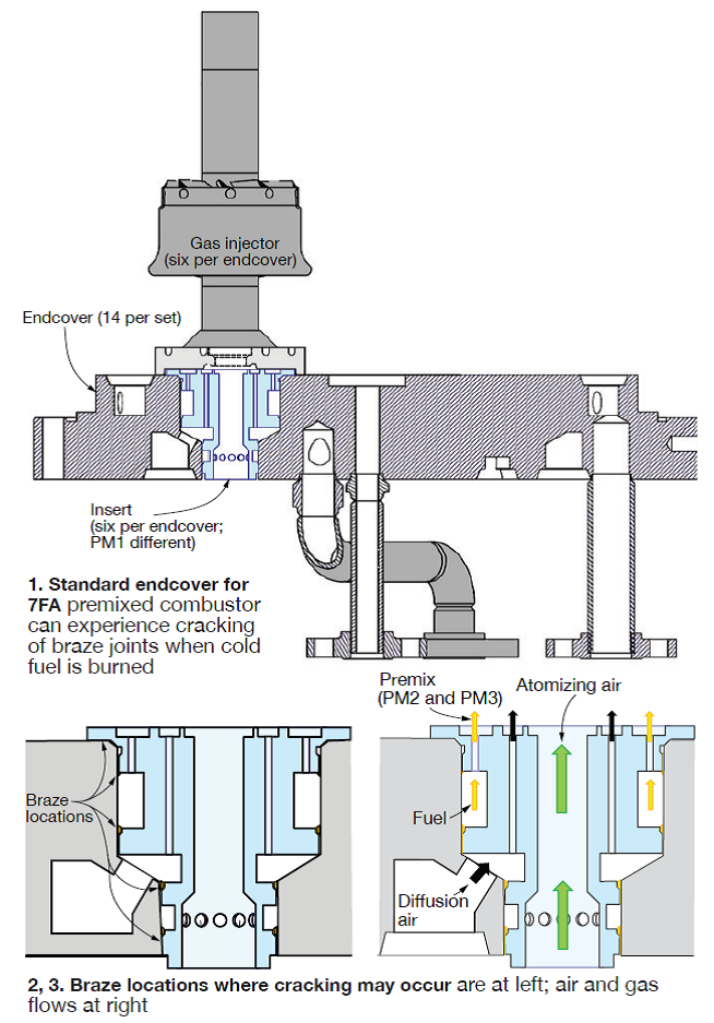
Thermal stresses are a contributor because temperatures in the susceptible locations can cycle from 100F to 700F. For fuel nozzles of OEM design, cracking creates the opportunity for gas to leak into and contaminate burner-tip cooling air. This scenario can create emissions and tuning challenges.
Incoming inspection is the first step for endcovers received at the Sulzer shop. In addition to the relatively standard procedures for visual inspection, recordkeeping, etc, flow testing of all circuits is conducted on each endcover. Flow testing and pressure testing of all gas injectors is next, followed by ultrasonic cleaning of all parts. Components that fail the pressure test are inspected by digital x-ray.
Andrepont explained the challenges associated with completely stopping leaks without replacing the insert (refer back to Fig 1). The braze repair must wick into the cracks between the original braze, Amdry 915, and the Type-304L endcover material. The braze material selected for the repair must wet below the Amdry 915 solidus temperature of 1760F. Also, a safety factor >7 must be achieved on the braze joint to satisfy ASME requirements.
Sulzer’s proprietary braze has a solidus temperature of 1620F and a braze range of 1800F-2000F, which is lower than Amdry 915’s 2075F-2200F. Also, the braze gap achieved with the Sulzer material ranges from 0.000 to 0.002 in., less than the 0.002 to 0.020 in. possible with Amdry 915. Finally, the corrosion resistance of the Sulzer material is equivalent to that of Type-314 stainless steel.
Sulzer engaged a third-party consultant for external repair-process validation. Mechanical testing of the repaired braze revealed the following:
- Ultimate tensile strength of 22.9 ksi (ASME Section IX) confirmed by an independent laboratory.
- Peel test revealed <4% inclusions.
- Safety factor (strength of joint divided by the force exerted) was greater than 21.
In addition, the braze joints were leak-free under a pressure test to 600 psig.
Andrepont next stressed some of the key requirements of a successful repair, including the need for contaminant-free surfaces. Ultrasonic cleaning and hydrogen cleaning in a vacuum furnace are critical to this goal. Next, the Sulzer braze is applied to all four joints without removing the inserts. Braze weight used is measured and compared against the approved repair spec.
The braze run is conducted in an argon-purged vacuum furnace with strict control of both temperature and ramp rates. Visual inspection, pressure test of all circuits, flow test of all disassembled parts, and dimensional inspection are among the final checks to validate a proper repair.
To date, Sulzer has repaired four sets of endcovers. One set recently was returned to the shop after its service run; all inspections and tests met expectations.
“Mitigating Risks Associated with Delivering a Cost-Effective Outage on Time and on Budget,” Freddy Alvarez, EthosEnergy—a Wood Group-TurboCare venture.
When you listen to as many vendor presentations as the editors, you come to truly appreciate the Freddy Alvarezes in the industry. There aren’t many. This former plant and asset manager, now director of operations for EthosEnergy, had the audience engaged from the start to the finish of his highly interactive, candid presentation on outage planning, preparation, and execution. Alvarez’s extensive deck-plates experience gives him a unique perspective from which to provide meaningful guidance to users who now do what he did for so many years.
Example: After you have thought of everything, rethink everything. On the importance of logistics in planning, Alvarez recalled not being aware that a Nascar event was in town on a critical weekend during an outage. Hotels were booked, forcing crews to stay a long way from the plant; traffic extended commuting times; restaurants were crowded and the waits for meals long. This put a significant strain on personnel and schedule, he said. Alvarez got burned by Nascar again, but the second time it was a forced outage.
There was good give-and-take on the subject of shift duration. Alvarez prefers 10-hr shifts to 12. Most in the room agreed with one attendee saying that he believed the productivity of a 10-hr shift was higher than that for a 12-hr shift. Another discussion built around a user’s concern regarding the lack of attention to detail by the OEM when wrapping up an outage. In his experience, there’s a mad dash to finish and many simple, but important, things are overlooked—such as valve positioning.
To benefit from Alvarez’s experience, access the article compiled by the editors in CCJ 3Q/2013, p 30, based on a webinar conducted by the outage expert covering much the same material as he did at the 7F conference.
“Latest Advancements in 7FA Repair Technology,” Jason Huxol, PW Power Systems.
Huxol addressed six component issues and repair solutions associated with the 7F turbine section and transition pieces (TPs) during his time at the podium. It was an ideal technology review for this audience: Users with limited experience on F-class engines were exposed to the types of damage to look for during the next overhaul, those familiar with the issues learned about viable repair solutions to consider. Session time constraints limited the speaker to five or six minutes on each topic, which kept the presentation in high gear and attendees engaged.
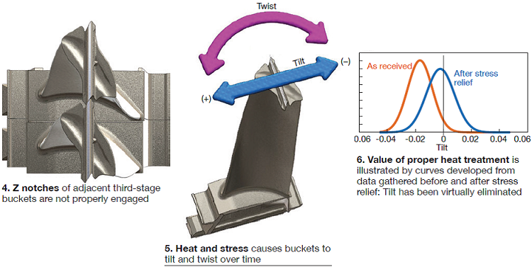
1. Third-stage bucket tilt and twist. Huxol began by explaining the importance of good z-notch engagement. Over time, clearances between adjacent 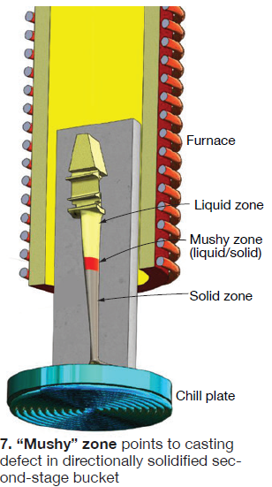 buckets open up (Fig 4) as heat and stress cause the airfoils to tilt and twist (Fig 5). When the joint closes and the rails of adjacent blades contact each other, as shown in Fig 4, the condition is known as “(+) mismatch,” where “mismatch” is the axial distance between adjacent blade shroud seals. When the joint opens up, the condition is known as “(-) mismatch.”
Creep is the primary cause of tilt and twist (T&T) and its effects typically can be corrected with proper heat treatment as Fig 6 illustrates. However, Huxol warned that extending the run time (double or triple run) between repairs increases T&T issues and makes correction more challenging.
The speaker stressed the need for proper fixturing and tight process control to ensure a successful repair. Example: Heat-treat fixtures should orient airfoils vertically during hot isostatic pressing (HIP). He also recommended performing stress-relief heat treatment before making any disposition decisions.
2. Second-stage bucket defect investigation. A set of the OEM’s new-style (3 HPI) directionally solidified second-stage buckets, rated for 72,000 hours, was investigated metallurgically because shop inspection revealed indications near the airfoil/platform radius on 17 of the 92 airfoils. Investigators hypothesized that the root cause was a casting defect.
Results from tests in a rig like that illustrated in Fig 7 suggested that an “incorrect draw rate” in the airfoil/platform region caused partitioning of elements—such as molybdenum, tungsten, aluminum, titanium, and tantalum. This contributed to the formation of MC carbides and y/y’ eutectics.
 When exposed to heat and stress, the segregated elements arranged into undesirable topologically close packed (TCP) phases and cracks formed at the interface of the y-y’ matrix and the deleterious ? phase. Questions remain: Can the phases be solutioned? Can material be homogenized with diffusion heat treatment so the phases do not reappear during service?
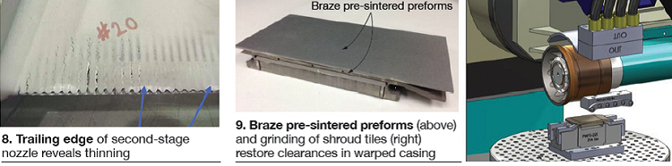
3. Trailing edges of second-stage nozzles tend to “thin-out” in service (Fig 8), Huxol told the group, urging timely repairs to reduce costs. One option shown during the presentation was a braze preform.
4. First-stage shroud tile repair. Casings warp over time, resulting in lost efficiency. Huxol showed the tile-height measuring and reporting chart PWPS uses to determine the optimal thickness for every tile around the circumference of the first stage so casing distortion can be corrected. Tile thickness is customized using braze pre-sintered preforms and grinding, as shown in Fig 9. Porosity of the tile coating, more than twice that of the OEM’s, allows controlled rubbing by first-stage buckets to maximize efficiency.
5. Factors influencing platform cracks, Huxol said, include thermal stress, casting quality, material properties, operational practices (speed of startups, shutdowns, load ramps, etc), and mechanical stress. He focused on the impact platform thickness has on crack severity at that location. Simply put: The thicker the platform the better its crack resistance.
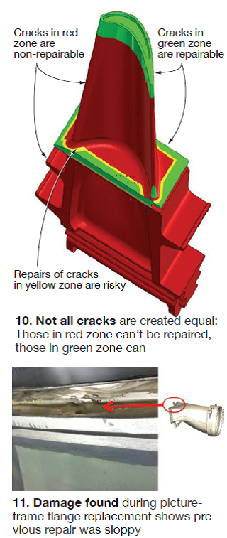
The speaker noted that the OEM has two different castings for its first-stage bucket—so-called M and P. You can find what you have by looking for the stamp in the bucket root area. M castings have a typical platform thickness of about 0.135 in.; P castings, 0.170 in. PWPS castings also are about 0.170 in. A handy graphic that Huxol included in his presentation (Fig 10) showed attendees where on the airfoil cracks can be repaired, where they can’t.
6. Dealing with TP wear and tear was the last segment of the presentation. Huxol suggested that users embrace the PWPS approach by removing the picture frame, replacing seal flanges and/or prepping for aft-seal modification. Opting for the recommended backside wear strip, he said, simplifies repairs during future outages. As Fig 11 shows, it is important for owner/operators to closely follow repairs through the shop.
“Capital Parts Planning: Effectively Managing a Significant Corporate Investment,” Tom Christiansen, Strategic Power Systems Inc.
SPS has been tracking gas-turbine parts for customers since 2005 and now has 48 sites with more than 200 units under contract—including several dozen F-class GTs. Christiansen gave attendees good reasons for rigorous parts tracking. At the top of the list: It saves money because (1) repairs are better planned, (2) the cost of unplanned inspections/outages is minimized, (3) optimal useful life is extracted from all parts, and (4) parts and services can be scheduled early, thereby reducing expediting fees.
Christiansen conceded that tracking parts on initial installation was easy, but “life gets more interesting” in a hurry. Reasons: parts are pulled out; spares are put in a warehouse, sometimes repaired, other times not; parts are sent out for repair; sets are modified as parts are scrapped; new and used parts are purchased; parts are exchanged; spare sets of parts are installed in different units, etc.
“What’s the big deal?” he asked rhetorically. Here are some reasons:
- Data collection is tedious.
- Spreadsheets are prone to error. Plus, they are impractical for tracking parts on, perhaps, more than one or two units; and it’s not prudent to maintain mission-critical information in a unique spreadsheet. Example: It’s relatively easy to have the same part in different machines at the same time when working from spreadsheets.
- Ownership of the task by an individual is fleeting because of promotion, new job opportunities, etc.
- Parts-life algorithms are increasingly complex as OEMs try to mitigate risks—such as those caused by fast start/stop, rapid loading/unloading to accommodate must-take renewables.
- Multiple serial numbers associated with a given part.
- The task is not simply a parts inventory; the life history of each part must be maintained.
- Accuracy is paramount. Million-dollar business decisions are made using parts information.
Christiansen explained the value of a formal, consistent, and seamless process that is not impacted by changes in plant personnel, plant owners, outage and parts-repair contractors, etc. The value proposition was clear, especially when total fleet management is considered. However, getting started in parts tracking is big job, one requiring the commitment of senior management and diligent initial information gathering by plant personnel.
The process begins with written documentation and project definition. Many questions must be answered at project start—for example:
- What naming convention for sets of parts does the owner want to use?
- What are the relevant parts-life parameters?
- How do you differentiate parts owned by the OEM or third-party services firm?
- Is part position in an operating unit important?
- How do you treat multiple, missing, or inconsistent serial numbers? Regarding this point, keep in mind that information gaps are acceptable as long as you know where they are.
“Age and Design Issues Affecting the Maintenance and Reliability of GE 7H2 Generators,” Howard Moudy and Jim Zayechek, National Electric Coil.
It’s the rare frame user-group meeting where NEC’s Director of Services Howard Moudy is not among the speakers. Although the generator expert was invited to speak at the 7F Users Group meeting, he chose to participate in the Q&A session only, yielding the podium to Service Manager Jim Zayechek.
The focus of Zayechek’s presentation was stator endwinding vibration, a major deterioration concern on large generators for decades. He said that efforts to improve endwinding performance had been hampered by the lack of instrumentation capable of measuring vibration levels in service. But such instrumentation is now available, and together with endwinding bump testing, proactive steps can be taken to mitigate resonanace and high vibration levels.
Of course, he said, critical to success is having the knowledge and experience to implement corrective action based on test results. Blocking, tying, and bracing are specialized corrections requiring engineering evaluations and technical know-how.
Zayechek offered these recommendations on how to resolve resonance issues:
- Conduct a visual inspection to identify dusting or greasing, broken ties, loose or missing hardware, insulation wear, and arcing or burning caused by shorted turns.
- Evaluate the winding natural frequency and resonance by bump testing and by adding vibration transducers.
- Detune the winding if resonance exists. This can be done by changing the endturn bracing system. Be sure the N=2 mode is outside the exclusion zone and phase leads are well damped.
- Other options include the following:
1. Coat endturns with red-eye epoxy.
2. Fix/replace any broken ties or spacers.
3. Install additional ties or spacers.
4. Install a nose ring and tapered series blocking.
5. Install a more advanced retrofit bracing system like the NECCO Brace System.
6. Rewind the machine with an advanced bracing system.
Questions about generators? Get the answers, plus valuable background material, by joining today, at no cost, the International Generator Technical Community—more than 2000 members strong worldwide. CCJ