
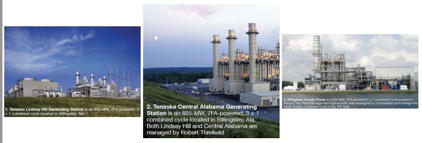
Over the past 10 years, Tenaska Inc’s Lindsay Hill and Central Alabama Generating Stations, and Southeast PowerGen LLC’s Effingham County Power (operated by Consolidated Asset Management Services), have received numerous CCJ Best Practices Awards for projects that improved performance, reduced emissions and O&M costs, and contributed to personnel safety (sidebar).
Given the opportunity to reflect on the best practices recognized by their industry peers over the years, personnel from the three plants selected projects they believe best illustrate the significant achievements possible when everyone is focused on improvement.
Click to enlarge
The underlying theme is the continual re-evaluation of plant activities, leading to changes that improve operations to better meet customer needs. Empowered personnel start with an idea (reducing startup times to save fuel, for example) or a known concern (such as the high cost associated with renting dewars of nitrogen) and then actively develop and implement a solution. Sometimes the fix is simple and inexpensive. In other cases, the answer requires a plant-wide effort perhaps lasting months or years.
Continual improvement is an ongoing process at these facilities and solutions may change as operating conditions change. Certain ideas address the needs of a plant that is laid up regularly; other initiatives have been fully integrated into plant operations and have ongoing value. What follows are solutions that have provided substantial benefits over the years. Perhaps you’ll identify one or more worthwhile implementing at your plant.
Performance monitoring (link)
Efficiency is always a priority, but the question is, “Who is responsible for maximizing it?” The short answer: Everyone.
In the early years of the CCJ awards program, operating data typically were analyzed at individual plants by engineers, who then made suggestions to the operations department on how to optimize performance. Later, a fleet-wide performance improvement programs were implemented to reduce operating costs, improve customers’ profit margins, identify operating problems, establish fleet consistency, and report measured results to stakeholders.
Adoption of best practices fleet-wide likely has been facilitated by promotion of those ideas in the CCJ and at the spring meetings of the Combustion Turbine Operations Technical Forum—the user organization providing the volunteer judges to evaluate ideas submitted to the editors from plants nationwide. Additionally, CTOTF, through Wickey Elmo’s Goose Creek Systems Inc, hosted the annual luncheons recognizing user achievements.
One engineer explained to the editors how beneficial ideas hatched and proven at the deck-plates level in a given facility gain fleet status. To develop a viable fleet solution, the company’s asset management team worked with engineers from all of its generating facilities to create a plant performance monitoring plan. “This is an ongoing effort,” the plant engineer explained. “We constantly look at things to make sure that we are reading data correctly and analyzing it properly.”
With the data, engineers create a detailed monitoring plan, gather information and best practices, implement the plan at their facility, and provide a summary of results and recommendations. Over time, many decisions that engineers used to make regularly have been programmed into the control system.
Value. Finding ways to operate more efficiently is always valuable, but beyond saving money, it also simplifies plant operations.
Takeaway. Don’t limit yourself. There is always something out there that you don’t fully understand and you should find a way to analyze it and learn more about it. Your biggest cost saving or biggest productivity boost might lie there.
Nitrogen generators for HRSG layup (link)
Years ago, one of the plants visited by the editors was laid up regularly during the shoulder months. To prevent oxidation in boiler drums, nitrogen blanketed the drum water.
The facility’s ops manager explained: “We were trying to eliminate the oxygen atmosphere above the liquid to minimize the opportunity for corrosion. To provide the nitrogen, we were using dewars, but that got to be expensive—especially when we were laid up for extended periods.”
A cost/benefit analysis showed that there was a better—and less-expensive—solution. The plant purchased and installed nitrogen generators, which have membranes that directly convert readily available compressed air to 95%-pure nitrogen.
“We moved the nitrogen generators up into the boiler penthouses, piped up compressed air, ran the nitrogen out to the drums, and capped the drums,” the ops manager continued. Note that the nitrogen generators are lifted up to the penthouse when needed, and removed when plant operation is resumed. After making the initial investment for the nitrogen generators, the cost of the inert gas essentially was reduced to system O&M expenses.
Value. Now running around the clock, the plant has very few layups, but personnel consider nitrogen generators a sound idea when conditions warrant. They saved money, paying for themselves within 24 months, and they improved safety, since workers no longer had to constantly move, connect, and disconnect cylinders.
“We learned that, if you think about it, you can find ways reduce costs. Your dispatch profile may change making some things less valuable, but always look for opportunities to increase efficiency,” the ops manager concluded.
Takeaways. Plants using a large quantity of nitrogen should consider if nitrogen generators make sense. Do your homework, size your nitrogen generators appropriately, and decide where you are going to install them.
HRSG reliability improvement (link)
One plant experienced several HRSG tube failures in its first year of operation. “We weren’t able to get all the water out of the tube panels (harps), when firing the gas turbine. The cost to repair tubes was very expensive and could take several days, reducing availability,” explained the ops manager.
Several causes were identified—including GT tuning during startup, quenching from attemperator control valve leak-by, quenching from over attemperation, and quenching from water left in the bottom of tube headers during a unit start.
To address the problem, the plant increased the size of HRSG drains from 1 to 1.5 in. (Link 3). Drum pressure is monitored and drains are closed automatically. Example: On a hot start, controls logic verifies drum pressure when the turbine is rolling at 30 rpm. Once that pressure increases by 50 psig, drains close automatically. The plant also changed control logic for the attemperators. Today, the temperature of steam exiting desuperheaters is at least plus 35 deg F.
Value. There were no tube failures during the second and third peak seasons and only minimal socket-weld failures attributed to commissioning fatigue. Reason: Operators are aware of potential problems associated with improper operation of drains and desuperheaters and have the tools to prevent them from happening.
Takeaways. Expect that it will take some time to train plant personnel and fine-tune the operation of drains and attemperators. Also, size drains conservatively; 1.5 in. works well for this plant, but a larger drain might be better for yours.
Improve steam-piping reliability off-peak (link)
One plant spent much of its fifth winter in layup. Even though the demand for power was low, the power-purchase agreement required that the plant be available. The ops manager explained: “When we weren’t operating, all of our steam piping was unprotected from the moist, corrosive atmosphere. This environment also can affect valves with tight clearances, contributing to their sticking.”
The solution was fairly simple. The plant rerouted dry compressed air, with a nominal dew point of -30F to -40F, for purging of the steam piping. Workers periodically checked the dew point of air going into and coming out of the piping to ensure the system was keeping the pipes dry. Total cost for the piping and a few connectors was minimal.
Since this facility does not have extended down periods today, the purge system is inactive. But others in cycling operation might find this best practice worthwhile.
Value. Reducing the corrosion rate contributes to high reliability of steam-system components and minimizes the transport of particulates to the steam turbine where they might wear critical flow-path components and adversely impact ST efficiency.
Takeaways. This is a proven method for protecting piping during extended layups. Carefully consider where to locate the inlet and outlet for the purge system, to maximize coverage. Also, remember to provide a way to monitor the dew point of purge air entering and leaving the piping system to assure you are getting the desired results.
Optimizing a cold start on one GT (link)
Starting a cold D11 steam turbine serving a 3 × 1 F-class combined cycle can be challenging under certain circumstances. Example: In a 1 × 1 configuration, you have only one HRSG in operation and it provides just enough steam to get the turbine up and running.
The D11 is started in reverse-flow mode—that is, steam is admitted to the IP (or reheat) section of the turbine first. As soon as the generator is synchronized with the grid, steam is supplied to the HP turbine and forward flow begins. The experts say the faster you get to forward-flow operation the better. Reasons include more even warming of the turbine—especially the shaft—and less thermal stress on critical parts. Plant personnel worked with the OEMs, and corporate engineering, to develop procedures for reducing startup time without exceeding recommended stress limits for critical HRSG and steam-turbine components.
One adjustment made to shave from five to 10 minutes off the start time was to increase lube-oil temperature while the unit is on turning gear. Previously, the oil was maintained at a relatively cool temperature when the unit was not in operation because of thermal degradation concerns.
At this and other plants as well, lube oil must be at operating temperature before the control system allows the turbine to ramp to 3600 rpm; low oil temperature would restrict the ramp rate. Collaboration among the parties revealed the lube-oil temperature could be increased during turning-gear operation, eliminating a possible “hold” before proceeding to synchronous speed.
Value. Since this procedure was implemented, the plant’s dispatch profile has changed and it rarely does one-unit starts today. But two-unit starts are done occasionally and the same approach applies to them, the editors were told. Getting to forward flow as quickly as possible is still the goal, the plant continuing to reap the benefits of the best practice formulated nearly a decade ago.
Going through the issue-resolution process, and evaluating and discussing the problem, increased the depth of knowledge of plant operators. They became better aware of exactly how equipment operates and developed a greater sense of ownership.
Takeaways. Getting an OEM to rethink guidelines in O&M manuals can be challenging. Users who have experience in updating procedures to be more in line with evolving business objectives often will tell you to expect that the first reaction from an OEM representative may be “not possible.” But if experts within your organization, and industry colleagues, believe your thinking is sound, keep pushing. You may find, as others have, there’s an OEM engineer better qualified to evaluate your proposal.
Industry leaders in the sharing of best practices
The Best Practices Awards program for owners and operators of generating facilities powered by gas turbines, sponsored by the CCJ with widespread industry support, celebrates its 10th anniversary in 2014. To commemorate the occasion, the editors are recognizing the plant staffs that have shared most generously the technology, procedures, and ideas they have used to assure top performance on a predictable and repeatable basis while minimizing emissions and maintaining a safe working environment.
There are two levels of awards to acknowledge the achievements at individual plants: Best Practices and The Best of the Best, as voted by a team of highly experienced volunteer judges selected from among the members of the Leadership Committee of the Combustion Turbine Operations Technical Forum. CTOTF, the most senior of the industry’s user groups serving owner/operators of gas turbines, celebrates its 40th anniversary in 2015.
Tenaska Central Alabama and Lindsay Hill Generating Stations, and Effingham County Power LLC, three of the five facilities receiving special recognition, share some of their best practices in the main text. In sum, the three plants cited here earned more than 30 awards during the program’s first decade—one-third of them Best of the Best (lists below).
The success of these facilities, and the two profiled earlier—Tenaska Virginia Generating Station and Klamath Cogeneration Plant—reflects a commitment to sharing by very capable management teams that have been in place since COD, in most cases. Additionally, continuity of ownership, dedicated personnel on the deck plates, and executive corps with deep experience in plant engineering and operations, played major roles in the performance achievements of the facilities recognized.
Tenaska Central Alabama Best of the Best Awards
2007 O & M
2006 O & M
2005 ManagementBest Practices Awards
2012 O & M
2010 O & M
2008 O & M (2)
2007 O & M
2006 Safety
O & M
2005 Management
Tenaska Lindsay Hill Best of the Best Awards
2008 O & M
2007 O & M
2005 O & MBest Practices Awards
2013 O & M
2011 O & M
2009 O & M
2008 O & M
2007 Management
O & M
2006 Safety
O & M
2005 O & MEffingham County Power Best of the Best Awards
2014 Performance Improvement
2013 Workforce Development
Performance Improvement
2011 Design
2010 O & MBest Practices Awards
2014 Workforce Development
O & M (2)
2013 Safety
Improve condenser performance (link)
Maintaining backpressure at the design value is important for reliable, efficient operation of the steam turbine/generator. Recall that low backpressure is conducive to top performance; very high backpressure can trip the turbine. Ten years ago, backpressure monitoring at most combined cycles built during the bubble was not fine-tuned, as it is today.
A performance-improvement initiative implemented after the plant had operated for a couple of years found that pressure monitoring equipment was not calibrated correctly, duplicate monitors provided different results, instrument tubes were leaking, rotameters were not functioning, etc.
Plant personnel started inspecting for, and repairing, condenser and valve leaks, which were found in expansion joints and cracked welds. They also started trending backpressure against design standards.
Value. Significant money has been saved over the years by closely monitoring backpressure and inspecting for suspected vacuum leaks. When found, leaks are repaired quickly.
Takeaway. Open a dialog with your condenser manufacturer. Find out what your vacuum pressure should be, based on design curves, and compare that to what it actually is. Then come up with a plan to identify air-in leakage and correct deficiencies.
Propylene glycol cooling-system mod boosts availability (link)
Until five years ago, or so, the atomizing air compressors serving gas turbines at one dual-fuel plant relied on open-cycle cooling water for the associated shell-and-tube heat exchangers. High operating temperatures caused some of the water to flash off in the heat exchangers, allowing minerals in the cooling water—such as calcium carbonate—to deposit on the hot tubes and impede heat transfer. Tube failures occurred.
To prevent flashing, plant personnel worked with the OEM to include the air-atomizers in the closed-loop cooling system. Its cooling medium, a mixture of water and propylene glycol, raised the boiling temperature of the heat-transfer fluid, thereby preventing scaling and tube failures. At the same time, a design upgrade increased the capacity of the heat exchangers—a permanent improvement.
Value. The periodic retubing/repairs required with the original cooling system were eliminated. Also, by not having to pull the roof off of the module, which was required to do this work, mitigated a safety risk. This capital improvement had a favorable payback period.
Takeaways. Pay attention to piping specs if you decide to implement this best practice. In this case, the original piping was passivated, but the new piping was not. Once the reconfigured system was placed in service, a rust bloom occurred.
However, that proved to be a learning opportunity. To deal with the bloom, plant personnel identified a new type of filter, enabling them to clean up the system without draining it and flushing the piping. The filtration system removed both oxygen and solids, leaving the coolant clean and clear.
Optimizing plant startups (link)
Ten years ago, one of the plants ramped up and down daily in response to market demand. It was expensive to start up and to shut down. “Back then,” the plant engineer said, “we were cycling the plant daily—even during the peak season. The offtaker wanted us to shorten start times to save on gas. Ultimately, we were able to trim about 30 minutes off of almost every start.”
The contract allowed a specific amount of time to get the 3 × 1 facility up and running; extra time was built into the schedule in case anything went wrong. To cut out the fat, the plant operators and engineers carefully analyzed all the information available, including operations data and information from previous starts and stops. They then created a very tight schedule, broken out minute by minute, to energize and de-energize the equipment.
Charts and tables detailing all steps were created for just about every scenario: hot and cold starts, the number of units being brought online, dispatch schedules, etc. As a result, the operators knew when to perform each step and could focus less on the procedures and more on plant operations.
Development and implementation of the new startup plan required working closely with the offtaker and developing a bond of trust with the customer; starting the plant on a tight schedule increased the risk of missing a dispatch time. Overall, though, very few problems occurred. The plant maintained a 99.4% availability on-peak and a 99.7% availability off-peak in the first year of the optimized-start program.
The plant no longer performs fast starts. “There is no benefit to performing accelerated hot starts today, so we don’t,” the plant engineer said. “But, if we have problems during startup, we know we have extra minutes built into our schedule to make corrections. If for some reason the unit doesn’t fire—and this happens occasionally—we still have time to restart and get the unit(s) online without missing our dispatch schedule.”
Value. While being done, the fast-start schedule saved the offtaker in the low six figures annually. A continuing benefit of the fast-start plan: When you have to stick to a tight schedule, there is no room for different shifts to start units in different ways. Performing consistent startups to enable the fast-start initiative has carried through to how the plant operates today. Every shift does things the same way.
Takeaway. If your plant starts frequently, there may be sufficient economic incentive to follow this example and shorten start times. Back-of-the-envelope calculations will tell if an opportunity exists.
Plant capacity improvements (link)
The plant’s first annual performance test revealed a significant drop in output since COD. Several reasons were cited for the poor performance.
Before the next test, everyone at the plant worked to address problems and improve performance. Plant personnel created an action list covering 30 areas of concern and then developed an action plan to review and correct everything on the list. Six months before the next test meetings and conference calls kept everyone up to date on the work.
Since HP steam pressure was a major limiting factor, the HRSG manufacturer was contacted. After careful consideration, the main-steam operating pressure was increased, DCS logic was revised, and safety-valve settings were adjusted.
Other improvements included correcting the turbine steam-seal pressure setting, improving backpressure and modifying the GT power augmentation logic to maximize steam flow. The next performance test revealed a 12-MW increase in output—or 7 MW above that recorded at COD.
Value. Every year since, plant personnel have run through the action-item list several months prior to the annual performance test, to be sure there are no unknown limitations on plant operations. And, it has worked well. Available capacity continues to increase annually in small increments.
Proof of the value in a continuous-improvement mindset: Best test results ever were achieved in 2014. One reason: Some things that used to be done manually have been automated and the control systems were adjusted to optimize plant output, while minimizing operator involvement in the process.
Takeaways. Personnel interviewed recommended that every plant create an action list and review it annually. Get as many people involved as you can, was the group’s suggestion: You can’t think of everything on your own and you may miss something major. Try to automate operational processes to the degree possible. If there is a difficult mode to operate in then see what you can do to automate it.
How to extend evap-cooler media life (link)
Several years ago, one of the plants sourced makeup for its evap coolers from the service water system. This water had low conductivity, but high levels of dissolved minerals. As water evaporates in the evap coolers and the remainder is recirculated, mineral levels increase, raising the conductivity. Probes monitor conductivity and, when a preset limit is reached, the control system automatically drains (blows down) the basin and adds clarified service water.
But at times the system could not add makeup fast enough and the evap coolers would trip offline for extended periods. Without evap cooling available, GT output had to be reduced. Another problem associated with the service water used for cooling: The minerals it contained deposited on the media, reducing its heat-transfer effectiveness. Media fouled relatively quickly and had to be replaced more frequently than expected.
The operations manager explained, “We recognized this was happening throughout the day, when we were running hard and generating a lot of power. So we decided to make a pre-emptive strike. We modified our valving and when the evap coolers were offline at night, personnel completely drained the basin and refilled it with fresh water. The next day the plant started up with water of very low conductivity. Of course, conductivity increased throughout the day, but it didn’t get high enough to take the evap coolers offline.”
Value. There are two benefits. First, the evap coolers remain in service throughout the peak hours of the day, letting the plant operate at maximum capacity. Second, this process extends the life of the media, which is expensive to replace. Originally the plant was changing media every three to five years. Now cycles are six or seven years.
Takeaway. If you are having problems maintaining conductivity during the peak hours, try this approach. It does not take much effort to implement and can pay for itself quickly.
Performance improvements
1. Exhaust thermocouple (T/C) failures on the plant’s two 7FAs, attributed to high-frequency vibrations, cyclic fatigue, and improver installation, placed the unit at risk for a controls-initiated trip. Change-out of failed T/Cs with the unit operating was not viewed as a solution because a spurious trip could occur—if wiring was inadvertently grounded during replacement, for example.
Revised control logic to protect against a unit trip when T/Cs fail in service was the solution. Implementation was completed within a few hours by plant staff. Since the logic was revised, failure of a T/C has not initiated a runback or trip.
Value. Reduces the number of equivalent starts used in determining when an engine overhaul is required as well as the likelihood of a unit trip during operation.
Takeaway. Considering the minimal effort required to change the control logic, the solution certainly is worth serious evaluation by any plant having to deal with T/C failures regularly.
2. Lower-than-expected cold-weather electric production attributed to condensate-system restrictions was resolved without capital expenditure by reducing the LP drum pressure. This link describes tests run to qualify the solution for consideration and eventual adoption.
Value. Use of LP preheater bypass valves to reduce LP drum pressure by about 5 psi increased plant output from 526 to 535 MW at 50F ambient; and to 545 MW at 30F ambient. Impact on plant heat rate was negligible. New controls logic enables automatic operation and greater operational flexibility.
Takeaway. If your plant suffers reduced output in cold weather, it would be difficult to pass on evaluating this solution.
Workforce development (link)
Training new employees and providing experienced personnel the opportunity to maintain their core electrical, I&C, and mechanical skills is a challenge at most powerplants today—especially considering the minimal staffing at most combined-cycle facilities. Project goal was to provide staff access to equipment conducive to realistic training and to incorporate as many job performance measures as possible to objectively evaluate each employee’s progress and capabilities.
Homemade stations for hands-on training enables employees to practice their skills, learn how to troubleshoot equipment and determine the root cause of failure, etc, right at the plant whenever the “student” has free time. While independent labs and training facilities met expectations, employee work schedules and travel distances made the offsite option infeasible. Details provided here can help others get started.
Value. The program, developed on a shoestring budget, is embraced by plant staff and has been a huge success, allowing technicians to qualify and re-qualify skills with minimal impact on their personal lives. Facilities have been replicated throughout the CAMS fleet and training stations are routinely shared among the operator’s other plants simply by moving them by truck among the plants on an as-needed basis.
Takeaway. This was most effective and least-cost approach to electrical, I&C, and mechanical skills development and retraining identified by plant management, and easily adaptable by others. Although out-of-pocket costs are low, the initiative required for successful program implementation should not be underestimated.
Operation and maintenance
1. Plant was challenged by excessive monthly imbalance/variance charges linked to a revised tolling agreement. Operators at the highly reliable facility, historically delivering greater than 99.5% of every scheduled megawatt-hour, found that the true problem was in the method used to ramp the plant up and down during startups, shutdowns, and normal hourly tag changes. Example: The plant was unloading/loading faster than the actual schedule allowed, resulting in significant variance charges.
Plant operators modified existing procedures and startup/shutdown checklists. They began to use a rate-limiting function, giving them precise control of how fast the plant would load during all load changes, startups, and shutdowns. Nothing in the plant was altered physically nor were any logic changes made affecting plant operation. The changes made were to existing procedures and operator mentality. The result: Imbalance costs were reduced from $0.35 to $0.06 per MWh.
Value. Annual savings in the hundreds of thousands of dollars were realized. Operators continue to learn how the plant can be penalized under tolling agreements and continue to adapt procedures to reduce plant financial liabilities.
Takeaway. Leave no stone unturned in your efforts to maximize the plant’s bottom line.
2. The plant uses several different types of oils for lubricating pumps and motors. In the past, equipment used to transfer oil was not labeled or controlled to minimize contamination by other types of oils or foreign material. Today they are. Cross contamination of lubricating fluids has been eliminated by assigning a particular transfer hose for a given service. Plant personnel are left wondering why they weren’t doing this since the plant’s COD.
Ammonia delivery mod improves safety (link)
Personnel explored the options available to reduce the costs and safety hazards associated with handling ammonia delivered to the plant in 300-gal chemical totes for boiler water treatment and for NOx control in SCR systems. Only minimal piping modifications were required to accommodate deliveries of ammonia in bulk. Truck delivery significantly reduces the changes of a spill by eliminating the need for plant personnel to handle the chemical totes—and it saves money. CCJ