A goal of every engine inspection is not to miss something that could contribute to a forced outage. Success requires qualified technicians equipped with the most sophisticated tools available and well connected to company experts with deep and applicable experience ready to help diagnose findings that may be unfamiliar to those at the plant site.
Mike Hoogsteden, director of field services, Advanced Turbine Support LLC, which inspects scores of GE E-class gas turbines annually, traditionally opens the 7EA Users Group meeting with the highly informative presentation, “What We Are Seeing in the 7EA Fleet during Our Inspections.” This is of particular value to first-timers requiring an engine orientation lesson as well as a primer on what to look for and where during inspections to assure reliable service from the generating asset. The photos Hoogsteden presents are invaluable.
Pat Myers, the de facto leader of the 7EA Users Group steering committee before his retirement as plant manager of AEP’s Ceredo Generating Station a couple of years ago, represented CCJ at the 2017 meeting and sat in on Hoogsteden’s presentation. Now a consultant, Myers shares with clients his extensive knowledge on plant construction, maintenance, and operation gained over four decades in management positions at both gas and electric companies.
Hoogsteden opened his presentation by suggesting that owner/operators review Technical Information Letters (TILs) issued by the OEM for their engines, take notes, and bring their questions to the next user-group meeting. Colleagues and participating equipment/services providers, he said, are the best source of advice on what’s important and what’s not.
The five TILs at the top of Hoogsteden’s list for 7EA users are the following:
-
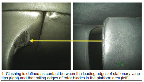
- 1884, “7EA R1/S1 Inspection Recommendations,” which addresses the need to inspect R1 and S1 airfoils for possible damage caused by clashing—the unwanted contact between the leading edges of S1 stator-vane tips and the trailing edges of rotor blades in the platform area.
- 1980, “7EA S1 Suction Side Inspection Recommendations,” which advises users to inspect for crack indications on S1 vanes made of Type-403 stainless-steel, regardless of whether clashing damage is in evidence on S1 and R1 airfoils.
- 1854, “Compressor Rotor Stages 2 and 3 Tip Loss,” which suggests blending and tipping to mitigate the impact on availability and reliability of R2 and/or R3 tip loss. This TIL supplements information provided by the OEM in the O&M manual provided with the engine.
- 1562-R1, “Heavy-Duty Gas Turbine Shim Migration and Loss,” which informs users on the need to monitor the condition of compressor shims and corrective actions available to mitigate the risks of migrating shims.
- 1744, “S17, EGV1, and EGV2 Stator-Ring Rail and CDC Hook Fit Wear Inspection,” provides guidance on the repair of dovetail wear and suggests hardware and software enhancements available to mitigate the potential risk caused by operating conditions that promote such wear.
TIL 1884. It took years for the OEM to address clashing in a TIL (Fig 1). Hoogsteden believes Advanced Turbine Support was the first company to alert the industry to this phenomenon—back in 2006. TIL 1884 was issued in spring 2013.
During the intervening years, Advanced Turbine Support worked closely with the user group, Myers on point, to share inspection data important to problem definition and solution. Developments in inspection technology contributed to a better understanding of first-stage findings and provided information of greater value for the resolution of issues.
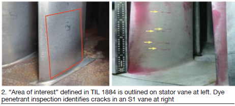
TIL 1884 went beyond clashing, recommending the checking of stator vanes for cracking in the co-called “area of interest” (Fig 2). Lock-up of vanes in carbon-steel ring segments can cause higher-than-normal operating stresses, which the OEM says “reach a maximum on the suction side of the vane near the mid-chord location.”
Hoogsteden’s suggestion to mitigate the possibility of serious damage from clashing and cracking is to perform an in-situ eddy-current (EC) inspection on the trailing edges of all R1 rotor-blade platforms and the entire suction side of every S1 stator vane from platform to tip each peak-run season or every six months.
TIL 1980, issued January 2016, essentially is an “addendum” to TIL 1884, addressing S1 vanes installed in legacy 7EAs (1996 and earlier) made of Type 403 stainless steel. This material is more susceptible to mid-chord cracking than the GTD™ 450 alloy used in the manufacture of vanes since 1997.
TIL1980 recommends inspection by visible means or by fluorescent dye to reveal suction-side cracks that might be present. Hoogsteden mentioned in his comments on TIL 1884 that these methods are inferior to EC for this purpose. He added that if the vanes are coated, visible or fluorescent dye penetrant inspections may not be dependable, nor have an acceptable probability of detection.
Regarding the effectiveness of ultrasonic (UT) inspection for this purpose, if coating degradation—such as disbonding—occurs, the value of UT could be compromised.
TIL 1854, released in August 2012, informs owner/operators of E-class compressors about the blending and tipping of second- and third-stage rotor blades it recommends to mitigate the negative impact on availability and reliability caused by tip loss from heavy rubs and/or corrosion pitting.
The OEM says fleet experience and engineering analysis have concluded that compressor rubs can be caused by casing distortion that progresses over time, and by hot restarts initiated between one and eight hours after shutdown. The latter causes critical clearances to decrease. Corrosion pitting, by contrast, can create a local stress concentration that may result in tip loss via high-cycle fatigue.
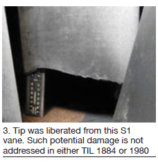 Hoogsteden pointed out that although this advisory does not address first-stage rotor blades (Fig 3), they too can suffer tip loss and should be included in your inspection regimen. For R1 and R2 rotor blades showing signs of tip distress, Advanced Turbine Support recommends, at a minimum, a visible dye-penetrant inspection to determine if radial cracks have initiated. For R3 blades, the company suggests a minimum of a 360-deg roll with a close-up inspection of all blade tips at the same intervals.
TIL 1562, issued January 2007, is likely the most familiar of the advisories in this group of five because it is more than a decade old and shim liberation has been discussed frequently in user-group meetings and in CCJ ONsite.
Hoogsteden recommends users develop a shim map for their compressors to identify locations where shims might have been installed, then audit those locations for shims remaining. The map should be updated after every inspection. Shims protruding from the case by less than one-quarter of an inch should be monitored regularly. When the shim protrudes into the flow stream one-quarter of an inch or more it should be removed or ground off.
TIL 1744, issued September 2010, said 7EAs operating at part load when ambient temperature is less than 40F are at risk for major damage caused by the lifting of 17th-stage vane segments—and EVG 1 and 2 as well. As the segments lift up they damage the hook fits and turn into the rotating blades.
A non-OEM repair procedure described at a user group meeting attended by the editors involved milling of the damaged slot to accommodate 18-in. inserts. They were installed in the upper and lower halves of the case to retain the new vane segments. The inserts are held in place with setscrews. The user describing the procedure cautioned against considering it a permanent fix because a root cause analysis had not been completed.
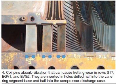
Another TIL 1744 solution comes from Rodger Anderson, DRS Power Technology Inc, well known to 7EA users for his widely used pinning mod to prevent shim liberation (TIL 1562). Here, Anderson uses compression coil spring pins to absorb vibration and arrest fretting wear of compressor vane ring segments in rows S17, exit guide vane 1, and EVG2 (Fig 4). As shown in the photo, the holes for the coil springs are drilled half into the base of the vane-ring segment and half into the compressor discharge case. To date, the procedure was said to have been implemented successfully on three 7EAs.
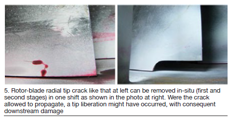
New capabilities. In closing, Hoogsteden brought attendees up-to-date on capabilities now at his company’s disposal for in-situ repair of compressor components. Recall that only a few years ago, in-situ machining was generally confined to the first and second stages of the compressor (Fig 5).
Today, Hoogsteden said Advanced Turbine Support has been successful in developing and proving tooling for blending vanes and rotating blades deep into the compressor via the bell mouth. He showed photos of blending on S11 vanes and R12 blades. The latter blend was about 1 in. along the length of the blade and about 300 mils deep.
Hoogsteden also mentioned that the company could cut off protruding shims deep into the machine by coming in through the back end of the compressor.
The learning never stops at user-group meetings. One of the discussions at Advanced Turbine Support’s stand during the vendor fair focused on the presentation by a user earlier in the day who had discovered cracks in the 17th-stage vane slot during the replacement of blades on two units having between 550 and 700 starts (round numbers) and fewer than 3000 hours of service.
The cracks were found near where the flat-bottom slot transitions to a radius on the inlet end and were blended out. Typically, they were about 1 in. long and up to 30 mils deep; several cracks ran over the edge of the wheel by about 0.100 in. One of the units had crack indications on more than 90% of its slots; the other machine just had “many” cracked slots. Another user in on the discussion said he had observed similar cracks when replacing 17th-stage blades on his 7EA.
Hoogsteden said such cracks on the 7EAs appeared similar to those addressed by TILs 1971 and 1972 which covered cracking in F-class units designed with flat-slot-bottom dovetails in compressor wheels for stages 12 to 17. He commented that company technicians would add this to their list of things to look for when performing 7EA inspections.