Diaphragms are a hot topic at most conferences where owner/operators gather to discuss issues with their steam turbines, such as the Steam Turbine and Combined Cycle User Groups operating under the Power Users Group umbrella. To get the most from these meetings, it’s important to know the basics of steam-turbine design, the differences among machines offered by the leading manufacturers, and typical challenges faced by O&M personnel.
The intent of this article, written by Moe Fournier and Bryan Grant of Advanced Turbine Support LLC, is to provide users a backgrounder on the different types of steam-turbine diaphragms and their associated repair challenges. Recall that the purpose of the stationary blades in a diaphragm—a/k/a nozzles—is to redirect steam from the exit of one rotating stage of blades into the entrance of the next rotating stage. The design intent of the nozzle is to optimize both the angle of steam flow and its velocity into the downstream stage of rotating blades to maximize energy conversion.
Diaphragms are a two-piece assembly consisting of upper and lower halves that are installed in the upper and lower halves of the steam-turbine casing, respectively (Fig 1).
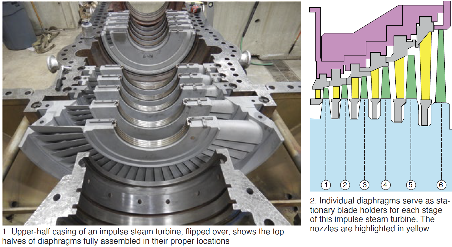
Recall that impulse turbines (Fig 2) typically have far fewer stages than an equivalent reaction turbine. Thus, the energy transfer across each stage of an impulse turbine is much greater than it is in a reaction turbine.
Almost all of the stage-to-stage pressure drop in an impulse turbine occurs across the stationary blades, virtually none across the rotating blades. This means stresses on an impulse blade holder (diaphragm) are significantly higher than they are for a reaction blade holder—dictating that impulse stationary-blade holders be axially larger and more robust than reaction ones. Most are of welded construction to tie all parts together rigidly.
Because they are stationary components, diaphragms often do not receive the same level of attention as rotating blades/buckets. However, improper maintenance and/or repair of diaphragms can have a negative impact on steam-turbine thermodynamic performance. Plus, the mechanical failure of a diaphragm can cause significant turbine damage. Damaged diaphragms also can act as a stimulus on downstream buckets leading to their premature failure and consequential damage to the turbine.
Diaphragm designs
Spacer-band construction (Fig 3), the most common style of impulse diaphragm for many years, remains the industry’s most prevalent design. It is characterized by individual nozzles without sidewalls, typically made of stainless steel, that are inserted into profiled holes in thin stainless-steel spacer bands that form the inner and outer flow paths for the steam.
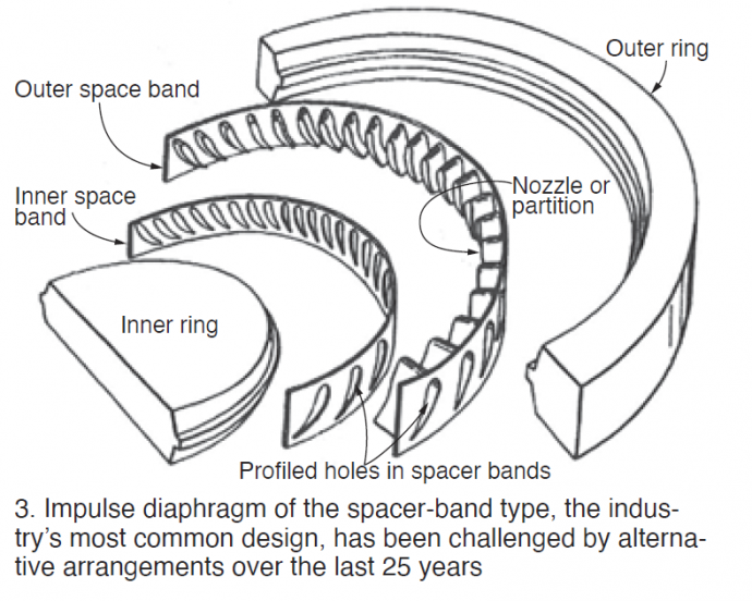
The spacer band and nozzle subassembly are structurally welded to the inner and outer rings, normally in four places (inner and outer ring, inlet and exit sides) to form the diaphragm. The weld process typically used is MIG or submerged arc; stick and electron beam welding are less common.
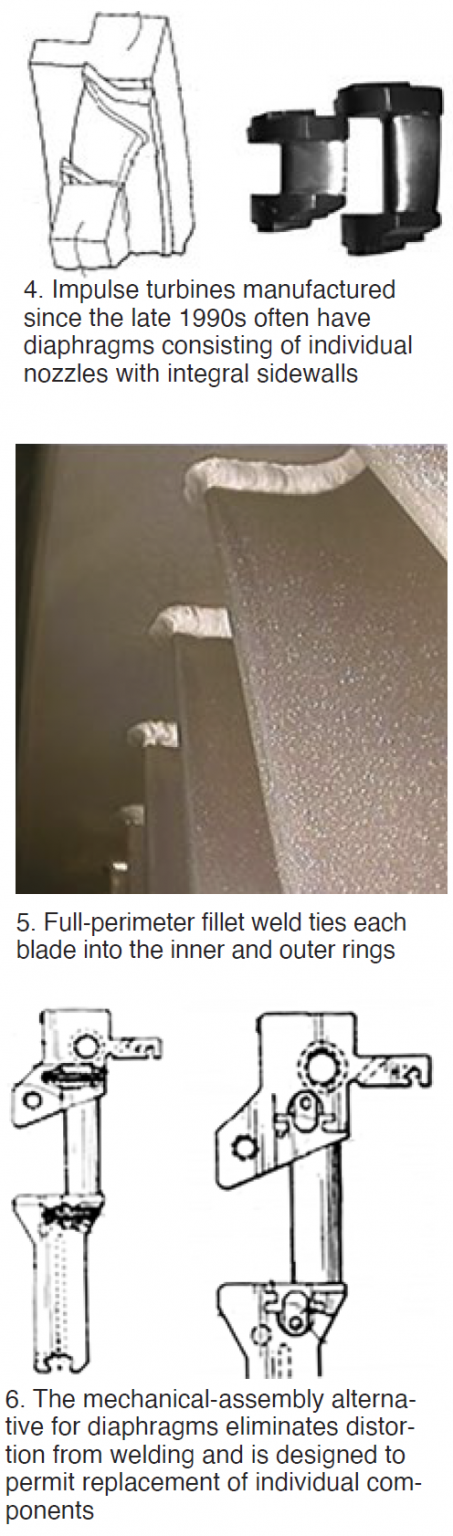 Integral sidewall construction (GE singlet, Alstom platform, etc) generally is found in impulse turbines installed since the late 1990s (Fig 4). It consists of individual nozzles with integral sidewalls, typically of stainless steel. The nozzles are structurally welded to the rings, normally in four places (inner and outer ring, inlet and exit sides). Weld process used usually is MIG or submerged arc; stuck and electron beam welding are less common.
Fillet fabrication construction (Fig 5) is very common on the last few stages of LP steam turbines. It consists of individual nozzles, usually of stainless steel, welded directly to the inner and outer rings using full-perimeter fillet welds. A TIG weld, using an Inconel or stainless filler wire, is typical. The nozzles can be solid or hollow and may incorporate moisture-removal features.
Mechanical assemblies are less common but are being offered by some OEMs because they are said to eliminate distortion from welding. In theory, they allow you to replace individual components in the diaphragm. Fig 6 shows two patented concepts.
Failure modes
Steam-path distortion and/or blade/nozzle mechanical damage (including foreign-object damage, solid-particle erosion, cracking, and moisture erosion) are the most common failure modes for diaphragms.
Nozzle mechanical damage and blade flow-path distortion can contribute to three significant failure modes for the steam turbine. They are:
-
- Distortion at the nozzle opening adversely affects turbine thermodynamic performance and efficiency because it suboptimizes flow from the nozzle to the downstream rotating bucket.
- For long blades, changes in nozzle exit openings are conducive to variations in the impulse on the downstream bucket and can lead to bucket resonance/vibration and premature failure of the rotating blades.
- Nozzle damage can lead to stress risers and mechanical failure of the nozzles themselves, which, in turn, can cause severe or catastrophic downstream damage to rotating buckets.
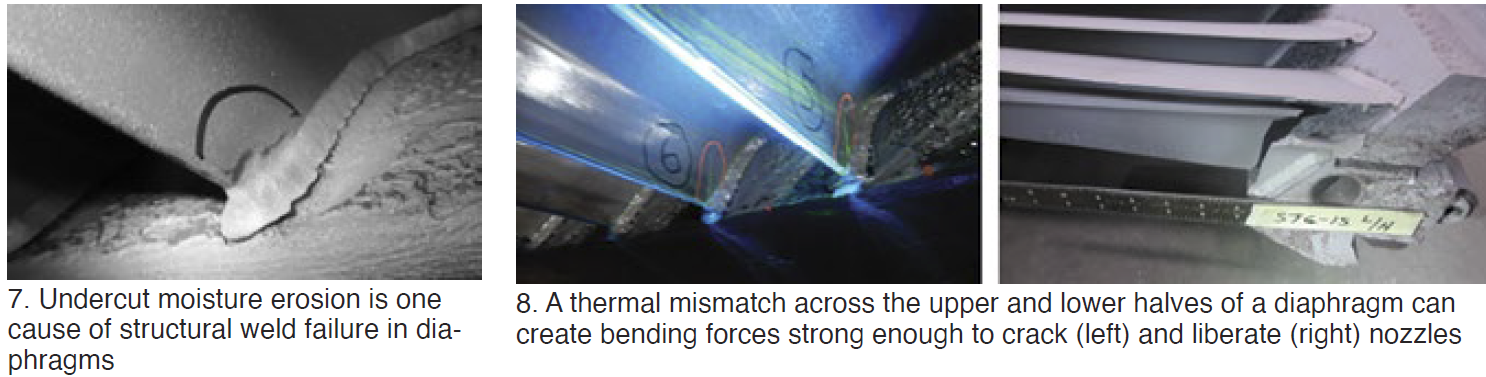
Structural weld failure. When the structural welds that tie the nozzles to the inner and outer rings fail, the diaphragm is likely to collapse and move into the downstream rotating buckets. This can cause significant damage to steam-path internals, up to and including catastrophic failure of the turbine. Failures often can be attributed to inadequate weld tie-in, improper weld application, and undercut erosion (Fig 7).
Nozzle failures. Although not a common cause of failure, a temperature difference between the diaphragm’s upper- and lower-half components can create forces strong enough to crack and liberate nozzle partitions. Condensate introduction typically is the cause of a thermal mismatch (Fig 8).
Dishing (creep). Diaphragms designed and manufactured with less-than-desirable materials or inadequate structural-weld depths, can, over time, and at elevated temperatures, distort (creep) in the direction of stress. Eventually, this causes the diaphragm to rub against the downstream rotating bucket stage, often resulting in significant damage to steam-path internals, and possibly catastrophic turbine failure.
Seal degradation. Diaphragms typically incorporate seals to prevent performance-robbing steam leakage around bucket tips and along the rotor shaft. When seals are damaged—especially seal tips—their effectiveness at keeping steam in the as-designed pathway is greatly diminished and efficiency suffers. Worse still, if the seals rub against mating components, they can cause surface cracking on the bucket covers and/or rotor shaft. Such cracks can propagate and lead to bucket or shaft failures.
Most diaphragm designs incorporate replaceable seal strips, which should be inspected, straightened and sharpened, and/or replaced at major-inspection intervals. Proper planning is required to ensure the correct spares are on hand to support component replacement.
Repair challenges, risks
Steam-path sections of all diaphragm types. The goals for repairing nozzles and sidewalls of a diaphragm are the following:
-
- Remove stress risers in the steam path that could lead to mechanical failure of the diaphragm.
- Restore the flow path (nozzle opening) to reduce opening-to-opening variations that can cause undue stresses on downstream buckets and premature failure.
- Ensure diaphragm steam flow into downstream buckets is optimized for thermodynamic performance.
The repair challenges are to understand and apply the correct repair techniques and to preserve flow-path integrity with respect to the three goals above. When the repair involves welding, selection of weld process, weld materials, and proper application of post-weld heat treatment (PWHT) is critical to a successful and lasting repair.
Structural repairs to welded diaphragms. Repairs involving the structural weld require a finite determination of the construction type and the axial depth of the OEM’s structural weld, as well as a basic understanding of the stress fields in the diaphragm.
Additionally, for structural repairs to rings and/or sidewalls, welding must account for the very thin nature of the space band (or hollow ring) and its tendency to distort. Keeping the sidewall in the correct radial location is critical to unit performance; minimizing distortion of the steam path is critical to unit performance and the diaphragm’s fit into the turbine.
Weld repairs also require knowledge of the material types for each component. Material verification testing is recommended before any welding is performed. PWHT must be evaluated based on material types and weld repairs.
Repair of mechanically assembled diaphragms. For blade and steam-path repairs, the challenges noted above apply. For structural repairs to any diaphragm components (rings, etc), knowledge of the component material is necessary. Material verification testing is recommended before any welding is performed. PWHT must be evaluated based on material types and weld repairs. One more concern: Make sure the proposed repair does not negatively impact the mechanical joining feature at the ring-to-nozzle interface.
Best practice: Review proposed repairs on a case-by-case basis with a full understanding of the mechanical stress transfer mechanism of the diaphragm assembly.
Seal repair/replacement. While some refurbishment of seals is possible, replacement typically is the best solution. Depending on the type of seals, challenges can range from procurement cycles to installation techniques; knowledge of the seal design is critical.