
Reconfigured heat-trace system assures accurate drum-level measurement

Heat-tracing challenges faced by plants in cold climes often are a discussion topic at user-group meetings. There are many suppliers of heat tracing and many different approaches to preventing freeze-ups. Beyond the obvious proper design and installation, critical to success is reliable operation of the control system and instrumentation charged with turning on and off sections of tracing as necessary and alerting where failures have occurred so they can be corrected before damage occurs.
While manufacturers have a wealth of experience to share in design, install, and system troubleshooting, don’t expect them to understand your facility’s specific needs. Plant personnel have to pick up the ball after the contractor leaves the site and do the customizing necessary to accommodate the idiosyncrasies of weather and operational requirements. The best practice described below illustrates the value of experienced personnel in such problem-solving. The process illustrated and the road to the solution identified can serve as a model for others.
At Athens Generating Plant in the Albany (NY) area, cold winters and cycling operation challenged the facility’s heat-trace system—in particular the drum-level heat-trace system serving the heat-recovery steam generators for the three 1 × 1 G-class combined cycles.
Drums for the HRSGs are located 100 ft above the level transmitters; sensing lines run down the boilers into heated cabinets where nine drum-level transmitters are located. Because of the length of the sensing lines and change in water density, any difference in temperature between a variable leg and reference leg causes an inaccurate drum-level reading.
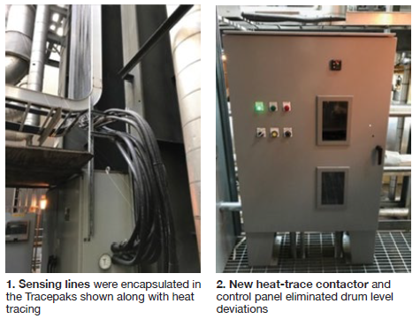
The sensing lines were run in Tracepaks—the product name for an insulated, weatherproof jacket offered by one manufacturer—with their heat tracing controlled by resistance temperature detectors (Fig 1). The RTDs provided input to a heat-trace panel that would turn the Tracepak bundles on and off. If the RTD did not turn off the reference and variable legs of each transmitter at exactly the same time, drum levels would deviate because of the temperature difference.
These deviations were exacerbated by ambient temperature and unit run status. If a unit was offline and ambient temperature 30F, all the heat tracing had to be on. Drum levels typically were fine in this condition. If the unit was started up, heat from the unit and the location of the RTDs would cause heat tracing to cycle on and off, contributing to the drum-level deviations.
Plant Engineer Hank Tripp and I&C Technicians Eric Van Zandt, Todd Wolford, and Bob Robinson considered several possible solutions, including the following:
- Installing one RTD per Tracepak.
- Pairing each drum-level transmitter with a single RTD.
- Combining sensing lines into a single Tracepak.
None of these alternatives produced consistently reliable levels during the winter months, causing several forced outages and forcing numerous de-rates to correct the level deviations.
Plant personnel believed the drum-level heat-trace system had become too complicated. They decided to simplify it by using a single contactor operating by ambient temperature via the plant’s DCS (Fig 2) to ensure all drum-level heat tracing was turned on and off at exactly the same moment, thereby eliminating temperature deviations among the sensor lines.
Using the DCS allowed staff to build logic into the control system that would factor in run status and ambient temperature. The solution ensures that the heat tracing operates only when necessary and also alerts operators with an alarm if the contactor is not energized when the heat tracing should be in operation.
Success! The heat-tracing contactor and control logic were installed in October 2015. Since then, the plant, owned by Talen Energy and operated by NAES Corp, has experienced no unscheduled call-ins, de-rates, or forced outages related to drum-level heat tracing. Plus, drum levels across all units—whether running or shut down—are consistent.
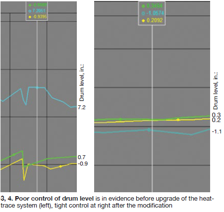
Fig 3 shows drum-level deviation before the new system was installed. One channel indicates 7.2 in., the other two approximately minus 1 in. Ambient temperature was about 30F. As shown in Fig 4, drum levels following system reconfiguration ranged from plus 1 to minus 1 in. at an ambient temperature of about 25F. CCJ
