
Effingham County Power receives its fifth Best of the Best Award—tops in the industry
The Best Practices Awards program for owners and operators of generating facilities powered by gas turbines, sponsored by CCJ ONsite and its companion quarterly print edition, and their user-group partners, celebrates its 13th anniversary in 2017. Over the years, more than 600 Best Practices entries have been received from 200 or so individual plants and fleets; the accomplishments of more than 100 have been recognized with awards.
There are two levels of awards to acknowledge the achievements at individual plants: Best Practices and The Best of the Best, as voted by a team of highly experienced judges who evaluate the submittals with weighted consideration of the following characteristics:
- Business value.
- Degree of complexity.
- Staff involvement.
- Duration of value.
The five most successful plants over the years in numbers of awards received are Effingham County Power, Klamath Cogeneration Plant, and Tenaska Virginia Generating Station and its sister plants Lindsay Hill and Central Alabama. Effingham, today owned by Carlyle Power Partners and operated by Cogentrix Energy Power Management, was the only one of the five recognized in the 2017 program and it came away with the facility’s industry-leading fifth Best of the Best Award.
The 2 × 1, 7FA-powered Rincon (Ga) combined cycle, rated a nominal 525 MW, began commercial operation in August 2003. Plant Manager Nick Bohl’s team—including Bill Beahm, Cheryl Hamilton, and Bob Kulbacki—submitted four entries this year. The first one on the list below was the most popular with the judges.
Safe grounding of a generator step-up transformer
When maintenance is required on the high-voltage system, conductors must be effectively grounded to earth so the potential difference between the conductors and other grounded components is zero. The temporary protective grounds used are 4/0 Cu “C” style; they vary in length from 8 to 25 ft. In the past, they were connected directly to the conductors and an approved grounding point using a manlift.
There were several issues with this approach, including the following:
- Damage to cables.
- Use of a manlift.
- A manlift is not rated for electrical use. Even if personnel in the manlift are using the proper electrical PPE, the workers at ground level are in danger if they touch the manlift because of the induced voltages from exposed conductors.
- The plant doesn’t own a manlift. This means it would be necessary to lease one at a cost of about $1400 per week.
- Operating a manlift within the close confines of the HV yard increased the potential for damage to insulators and arrestors.
The most practical place to install grounding cables on the low side (18 kV) of the GSU serving the gas turbines at Effingham is where the generator transitions from solid bus to ACSR cable (aluminum-clad reinforced steel). Because the bus and the GSU are at different heights, the ACSR cables are angled at approximately 45 deg.
Even if a bucket truck with a dielectric boom were used to assist in hanging the grounds, the angle and weight of the ground cable would put excessive stress on the aluminum conductors, causing the strands to separate. This was confirmed during an annual outage inspection of the substation.
A new method for hanging grounds safely and economically was needed. First, plant personnel tried using a step ladder positioned on the loose gravel. The weight of the grounding cable and the uneven surface made it unsafe. Next, technicians tried working off an extension ladder positioned against the GSU. The close proximity of the workers to the transformer, and the weight of the clamps, increased the possibility of component damage.
Ideas then were solicited from technicians who had performed this task in the past to determine a safe alternative. An employee with transmission-line experience recommended using grounding posts installed on the low-side insulators. He researched the various designs available and whether they were compatible with the voltage that would be present on the insulators.
Ground hanger studs were purchased and mounted on top of the insulators on the “H” structure serving the two GTs (Fig 1). This provided a fixed point of attachment for the ground clamp, which can be hung from ground level using an HV stick. Studs were installed by electrical contractors during a planned outage.
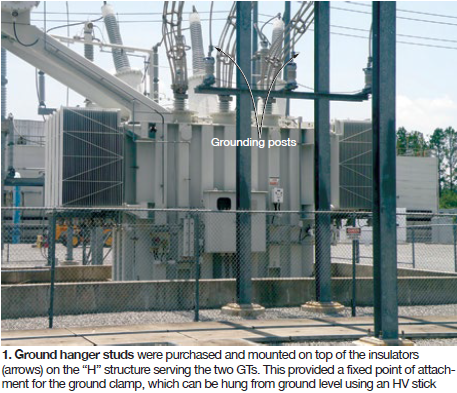
After installation of the grounding posts, technicians practiced hanging the ground clamps; all feedback was positive. Technicians liked the safety of being able to hang grounding cables from the ground versus climbing onto a ladder or using a manlift. Plus, use of the grounding posts means grounding cables no longer are clamped to the aluminum HV cable, eliminating the resultant wear and tear.
Success! Grounding posts are located directly above the technician’s head. This means the weight at the end of the stick is straight up and not at an awkward angle, making it easier to control the grounding cable being installed.
A longer HV stick (shotgun) was purchased, allowing the technician to hang the grounding cable from the ground without use of a ladder or scaffolding. The benefit: A more stable platform for the grounding process.
The grounding posts provide a defined grounding location and are clearly visible from the ground, enabling personnel to verify grounds are removed prior to closing any breakers. The grounding posts are bolted in position, so if there’s any damage they can be replaced easily during an outage.
Finally, eliminating the need for a manlift saves thousands of dollars annually.
Relocation of flow transmitter eliminates freeze-up, fouling
A condensate flow transmitter is critical to proper operation of Effingham’s hot-reheat (HRH) dump valve. It regulates condensate flow to control the temperature of steam dumped to the condenser.
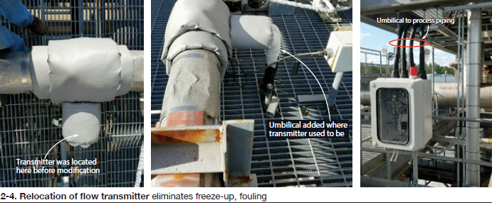
The transmitter was located directly off the condensate process line with carbon-steel piping and valves (Fig 2). It is insulated with both lag pads and heat tracing. In winter it would freeze, damaging the instrument and causing plant upsets. Damaged transmitters would have to be replaced at a cost of $1500 per.
During the summer, buildup of biological matter would clog the short process lines. It caused the transmitter to indicate flow even when the condensate system was shut down and the condensate block valve would not open because of this false indication. This was an issue when the HRH dump valves were placed in service, because steam temperature would increase until condensate flow demand was high enough to overcome the false indication.
Result: Several high steam-temperature alarms and potential damage to the condenser exhaust-hood spray. This required that the transmitter be re-zeroed and calibrated numerous times during the summer. Also, process lines had to be flushed periodically to remove any build-up in the sensing line.
A new location was identified for the transmitter and the instrument was relocated (Fig 3). The material costs were approximately $4500; all work was performed by plant personnel during a routine maintenance outage. The transmitter was placed in an insulated box with a heater to prevent freeze-up and damage (Fig 4). The transmitter’s process lines were extended and placed below the process piping. They are insulated and protected with heat tracing.
Success! Relocation of the transmitter eliminated the threat of freeze damage and the longer process tubing mitigated biological growth. The latter reduced the possibility of plant upsets and erratic readings. Also eliminated is the need for flushing out the lines and/or zeroing the transmitter prior to startup.
Empowered technicians, inexpensive mod boost reliability
By design, there is a transmitter that senses the exhaust-duct pressure of Effingham’s gas turbines and provides an input to the Mark VI control system. Also, there is one pressure switch that activates an alarm when its set point is exceeded.
There are two additional pressure switches that provide a trip signal to the Mark VI system if their set points are exceeded. The GT is designed to trip if any two out of three exhaust-duct pressure switches exceed their set points.
These switches and a transmitter were connected in series. Because there was only one test connection installed in the sensing line to calibrate the switches, they had to be tested together. But if tested together all three switches would exceed their set points, activating a turbine trip signal. Thus the only time the switches or transmitter could be checked or calibrated was when the unit was offline.
After a major outage while the plant was ramping to 525 MW, the operator received an exhaust-duct high-pressure alarm, Twenty-four seconds later GT1 tripped because two out of three pressure switch set points had been exceeded. The exhaust-duct pressure at the time of the trip was 21.9 in. H2O. Staff determined that set points for one or both of the trip pressure switches had drifted down since the last time they were tested. Lost generation for this event was 100 MW.
On a second occasion, while at steady state, GT2 tripped on high exhaust-duct pressure, which occurred at 23.7 in. Prior to restarting the GT, the set points for the exhaust-duct alarm and trip pressure switches were checked. All three pressure switches were set at 23.6 in.—the two trip-switch set points had drifted down by almost 2 in. The switches were last calibrated 45 days prior to the trip. Lost generation for this event was 147 MW.
For each lost megawatt of generation the plant is charged $150; therefore, trips can result in thousands of dollars in lost revenue. It was important to find a way of checking pressure-switch set points easily and to check them frequently during the year to prevent trips.
Space constraints militated against installation of individual sensing lines. Other switches on the GT roof had a separate isolation valve and calibration ports for their sensing lines, allowing calibration of switches without disassembling sensing lines to connect test equipment. Based on that knowledge staff decided to install a separate isolation valve and calibration port for each of the exhaust-duct switches.
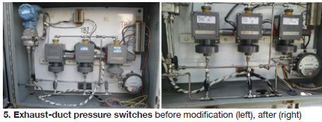
For about $100 a unit, technicians purchased the needed components to complete the sensing-line mod (Fig 5). With the GTs offline, technicians installed the isolation valves and calibration ports. At the completion of the modification, the tubing was leak-tested with air and the isolation valves were closed to ensure complete isolation to the instrument being calibrated.
In the short amount of time since this modification was completed, spurious exhaust-duct high-pressure alarms have decreased significantly. The ability to check the set points of switches has increased plant reliability.
Success! The ability to check and calibrate switches while the GTs are online has made this project noteworthy. For example, last June the plant remained online for 28 out of 30 days. During that time, personnel were able to check the switch set points weekly. A spreadsheet was developed to monitor the amount of drift and any adjustments required. Installation of improved switches has virtually eliminated trips attributed to drifting set points.
Lay up chillers dry in winter to protect equipment, save money
The GT inlet chiller system normally is taken out of service when daytime temperatures are consistently below 60F—typically December through March. When Effingham commissioned its chiller system in 2010 there was minimal experience on staff with winter layup. Plant personnel reached out to the chiller manufacturer and the chemical supplier for recommendations on how to prevent biological growth and minimize corrosion.
The first method used was to keep the system full and circulate the water for four hours, adding chemicals every three days during the off-season. The annual cost in chemicals and electricity for this approach was about $3300; plus, there was the possibility of freeze damage when the system sat idle.
The second method tried was to drain the entire cooling-water system by opening the vent and drain valves on the condenser and cooling-water pump. Once the system was drained, a nitrogen cap was placed on the cooling-water header. Adding one cylinder of nitrogen daily from a 12-pack was the direction provided to the operators, but it was not an effective solution for preventing corrosion. Leakage of nitrogen was one reason.
A quarterly service contract for the inlet chiller was the next solution tried and the one adopted. It calls for three operational inspections and one shutdown inspection annually. The shutdown inspection and condenser tube cleaning are conducted in the first quarter. To do the cleaning, one head must be removed from each of the condensers (Figs 6, 7). Since the layup methods described earlier were expensive and failed to prevent biological growth and corrosion, staff decided to pull a head and keep it off for the duration of the winter layup period.
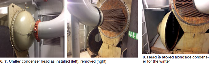
The current plan: Once the chillers are no longer required, the cooling-water system is drained and a condenser header from each chiller unit is removed and stored (Fig 8), allowing for complete drying of the system. Next, the service contractor is contacted and tube cleaning and inspection are scheduled.
The vendor responsible for the chemistry program also inspects the cooling-water system. Based on its findings, the effectiveness of the chemistry program is evaluated and changes made as needed.
Since instituting the practice of drying the chiller condensers during the winter, the corrosion rate has been reduced. In addition, no cooling-water tube leaks have occurred and no electricity and chemical costs incurred. Finally, since the entire cooling-water system is drained during the layup period, there is no need for additional insulation or heat tracing. CCJ
