
The powerplant may be ‘commissioned,’ but extensive work remains to get it shipshape

Woodbridge Energy Center is a nominal 725-MW 2 × 1 combined cycle powered by two of the first 7FA.05 engines to achieve commercial operation. It is owned by Competitive Power Ventures and operated by Consolidated Asset Management Services (CAMS) with Plant Manager Ken Earl at the helm. Given the leading-edge technology implemented at this facility, Earl and his team have been deeply engaged in plant activities since well before first fire.
The veteran manager is a believer of “owning” the operation of the plant from Day One. What he means is not to be in a position of blaming someone else for punch-list items after commissioning. To keep on top of things, Team Woodbridge implemented a formal process of system walk-downs during construction to correct as many oversights as possible before first fire. This level of involvement fostered the development of many best practices to ensure lessons learned would not be relearned.
Earl and team members Michael Armstrong, Justin Hughes, and Ryan Bullock share four of the plant’s best practices here. The first profiled below, Comprehensive plant heat-trace guide, received Best of the Best honors. This is the fifth Best of the Best Earl has had a hand in. The other four were awarded to Effingham County Power when he managed that facility for CAMS.
Coincidentally, Effingham, under new ownership, also was recognized with a Best of the Best this year—its first under Nick Bohl, who was promoted to plant manager when Earl accepted the challenge at Woodbridge.
Comprehensive plant heat-trace guide
Plant personnel found that poor installation practices coupled with the lack of documentation made it difficult to troubleshoot Woodbridge Energy Center’s heat-trace system. This required staff to spend roughly 60 man-hours per week identifying and fixing issues with heat-trace circuits not functioning as designed. The poor performance of the heat-trace system jeopardized reliability and operability by allowing critical equipment to freeze-up.
The central New Jersey facility was constructed as an outdoor plant with everything—including instruments, pumps, piping, control valves, etc—installed outside. Equipment must endure the elements of a Northeast winter, where temperatures may be below freezing for days on end. Obviously, equipment reliability depends on a functioning heat-trace system.
Woodbridge was constructed by a single EPC contractor with multiple equipment suppliers. Design of the heat-trace system was subcontracted to a reputable supplier while installation was handled by the EPC contractor’s craft electricians, who had little or no experience with heat-trace equipment.
The various scope-of-supply boundaries and types of heat tracing proved problematic. Many field changes were required to complete the installation—changes performed without the knowledge of the designer and poorly documented.
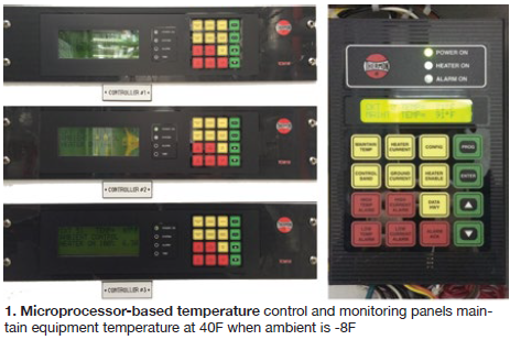
Heat tracing was designed to maintain an equipment temperature of 40F at an ambient of -8F. The heat-trace supplier implemented the use of microprocessor-based temperature control and monitoring panels (Fig 1) which required other new equipment—including various temperature sensors, new alarm capability, DCS integration, self-testing circuit cards, and programmable RTD outputs.
The lack of qualified oversite from the heat-trace designer during equipment installation and in preparing documentation of as-built conditions proved challenging for the plant operator once it took possession of the facility.
First step in fixing the problem was to bring back the original heat-trace designer to audit the entire system and identify and correct any deficiencies. This required all 612 individual circuits to be reviewed to ensure the correct materials were used along with the correct installation practices. Next, all the documentation was updated to reflect as-built conditions. This information and a thorough review ensured the system was designed and installed as originally intended.
With the proper installation and operational techniques identified for the new technology, the plant operator developed a heat-trace guide to provide a laymen’s approach to better understanding of equipment and operational requirements. In the guide, details which had been segregated because of scope breaks are included in one location, eliminating the need for multiple sources of documentation. The guide is written in plain language and includes pictures of installed equipment to better acclimate the reader and facilitate troubleshooting.
The guide includes the following major sections:
- Equipment and location defines what the pieces of equipment are, along with their associated location.
- Operational overview describes the system from beginning to end.
- General alarm and troubleshooting describes typical steps to take when an alarm is received. This section also advises the operator what information must be recorded to facilitate a work order in the event they are unable to troubleshoot the issues seen.
- Examples of equipment onsite describes with pictures each piece of equipment.
Success! Using the original design team to identify and fix the installation issues the heat-trace system achieved its specified objectives. System performance now is aligned with the original design intent, ensuring safe and reliable operation of plant equipment during times of inclement weather.
Upon release of the guide, personnel were immediately able to reference site-specific information for heat-trace issues in a timely manner. Today, only about 10 man-hours per week are required to properly troubleshoot system issues, down from 60. The guide also helped personnel identify equipment improperly installed, before it adversely impacted heat-trace performance.
In sum, the guide’s effectiveness has shifted the response from reactive troubleshooting to proactive analysis and has removed any uncertainties associated with the new technology installed at the facility.
Logic changes reduce blowdown quench-water use, save $30,000 per month
At Woodbridge Energy Center, blowdown and drains from each heat-recovery steam generator are directed to a dedicated blowdown tank where they are cooled with potable service water supplied by the local water authority. Quenched steam and water drains from the blowdown tank into a blowdown sump and is then forwarded to the cooling-tower basin via HDPE piping, temperature-limited at 140F.
The blowdown tank and drain sump have independent temperature control valves. The blowdown-tank control logic was programmed to maintain a temperature below 140F using service water for quenching. The sump was programmed to maintain 120F using a separate but similar quenching setup. Each of the blowdown tanks required 65 gpm of quench water, the sumps an additional 25 gpm each.
To reduce potable-water use, the blowdown tank temperature control logic set point was raised to 220F, allowing blowdown to flash off and leave through the outlet piping to the muffler with minimal or no need for quench water. The elevation of the muffler provides enough exposed piping that steam entering the blowdown tank can cool naturally and condense, reducing the need for quench water. The new alignment reduces the temperature of water remaining in the blowdown tank to less than 120F, eliminating the need for quenching in the drain sump.
Big saving. Service-water consumption has dropped by approximately 125 gpm since implementing the logic changes. This translates to a monthly saving of $30,000.
Safety program minimizes the potential for arc-flash injuries
Determining the appropriate arc-flash personnel protective equipment (PPE) was extremely difficult at Woodbridge Energy Center because of the complex nature of the installed arc-flash PPE and various scope breaks in arc-flash protection. The plant’s power distribution system was designed to restrict the incident energy level to a maximum value of 25 cal/cm2.
Differential protection, fiberoptic arc-flash detection, high-speed overcurrent protection, and maintenance switches were used to satisfy this requirement. Depending on the voltage and current rating of a particular piece of equipment, any one of these methods could have been employed.
The arc-flash rating for equipment with a “maintenance switch” could be changed dramatically by turning the switch on or off. Adding to the confusion, the arc-flash study performed by the EPC contractor during construction referenced NFPA 70E-2012 guidelines, which changed shortly after the study was completed when NFPA 70E-2015 was released.
Adding to the difficult nature of the protection was an arc-flash study over 300 pages with results for the incident-energy levels described not in alignment with NFPA 70E-2015 or the site’s arc-flash safety procedure.
Furthermore, the NFPA 70e hazard labels provided by the EPC contractor did not specifically call out a recommended level of arc-flash PPE, requiring the person performing the work to locate the piece of equipment in the arc-flash study and cross reference the incident energy level with the site’s safety procedure and NFPA 70E-2015. With so many different documents being used to accomplish one task, the risk of human error increased significantly; potentially hazardous situations could occur.
The first step in reducing the confusion regarding the hazard ratings was to ensure the site arc-flash safety procedure included easily understood PPE classifications. Following NFPA 70E-2015, site personnel aligned the plant’s arc-flash PPE with these three incident-energy levels: 0-1.2, 1.2-12, and 12-40 cal/cm2. For the 0-1.2 cal/cm2 range the company determined arc-rated uniforms and arc-rated face shield (as necessary) would be required and made them available.
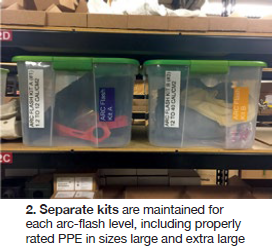
For the higher incident-energy levels, separate kits were created for each arc-flash level and included all of the properly rated PPE in sizes large and extra-large. The kits are contained in a clear storage bin stored in a designated location at the site and are labeled to reflect the arc flash rating and designation by color and letter (Fig 2). The color code and letter designation labels also are applied to each piece of power distribution equipment adjacent the NFPA 70e label. Specifically:
- Equipment rated <1.2 cal/cm2 is identified with a green label having white lettering stating, “Arc Rated Uniform.”
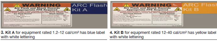
- Equipment rated 1.2-12 cal/cm2 has a blue label with white lettering (Fig 3) stating, “Arc Flash Kit A.”
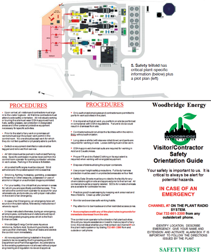
- Equipment rated 12-40 cal/cm2 has a yellow label with white lettering (Fig 4) stating, “Arc Flash Kit B.”
These same labels then were placed on the outside of the clear storage bins containing the corresponding PPE. Note: Equipment rated >40 cal/cm2 has a red label with white lettering stating, “No Energized Work Permitted.”
Safety made easy. Site personnel now can walk up to a piece of power distribution equipment and easily identify the hazards and proper PPE required to perform energized work, greatly reducing the risk of incorrectly determining the required PPE. In addition to significant increases in arc-flash safety, this best practice has reduced the time required to evaluate energized work requirements—from hours to minutes. Man-hour reductions could save $150,000 over the life of the facility.
Trifold for contractors keeps critical site information readily available
Combined-cycle outages require a large skilled workforce to complete a substantial amount of work in a short period of time. It is not uncommon to have over 150 contractor personnel working during a major outage, increasing the risk of a safety or environmental incident.
To mitigate this risk, all contractors are required to participate in an onsite safety orientation prior to beginning work.
This orientation covers the site safety and environmental requirements and procedures along with all of the applicable plant policies. Most contractors participate in dozens of site-specific orientations per year so keeping track of which policy/procedure applies to the current worksite is nearly impossible. Additionally, contractors may have little knowledge of the equipment and processes they are working on, and may be expected to carry out tasks that are not routine for them.
After the relatively short orientation, contractors are expected to recall vital safety information including evacuation locations, emergency contacts, locations of equipment, and hazards. Tall order.
So Woodbridge personnel developed a contractor safety orientation trifold pamphlet (Fig 5). Upon completion of orientation, each contractor receives a hard-hat sticker and a copy of the pamphlet, which they are required to have on their person when onsite. The sticker tells plant personnel who should have copy of the trifold.
The trifold, printed on durable cardstock material, includes critical plant-specific information—including emergency phone contacts, plant radio system channel, what to do in the event an emergency, summary of safety policies and procedures, and a plant plot plan that identifies contractor parking, smoking areas, restrooms, and the evacuation muster point, plus major plant equipment.
The safety trifold was inexpensive (less than $350) and has provided immediate results in improved awareness and safety culture. To date, the plant has not experienced a safety or environmental incident attributable to contractor personnel. The trifold makes critical safety information presented during contractor orientation accessible at all times. CCJ