
By Clyde V Maughan, Maughan Generator Consultants
Generator stator-bar insulation systems have experienced a steady evolution since the beginning of central powerplants in the early 1900s. Initially, 1900-1915, natural products were used—for example, shellac, mica flake, paper. These materials apparently worked well on small, low-duty units, but were inadequate beyond perhaps 10 or 15 MW.
As units grew in size, problems developed and during the period 1915-1950, “asphalt-mica” was the common system. These systems used mica, with a paper or cloth carrier, and vacuum pressure impregnation with carefully selected asphalt compounds. Initially, they performed well, with minor problems associated with puffing and asphalt bleeding if operated at too high a copper temperature—above roughly 95C.
But as generator size increased, the “tape migration” issue described in Ref 1 became so destructive that use of asphalt-mica systems was discontinued in the 1950s for generators rated higher than about 25 MW.
Problems with asphalt-mica systems led in the 1950s to the transition to thermoset resins, first polyester and then epoxy, for impregnating the mica tapes. From the 1950s to the present time thermoset systems have evolved upward in mechanical and electrical capabilities.
But during this period, generator ratings also have gone up, with associated mechanical and electrical duties dramatically increasing. For example, generators manufactured prior to 1950 would have normal electromagnetic forces in the slots of perhaps 2 to 3 pounds per inch of length (0.35 to 0.53 kg/cm), and an electrical stress of up to 45 volts per mil (2 kV/mm).
In modern generators the slot forces range up to about 110 lb/in. and electrical stress to more than 90 V/mil. Thus it should be no surprise that, although the evolving new systems generally performed fairly well, problems continue to occur to this day. Some of these problems have been very costly and some have been very persistent.
Asphalt systems, with their low slot forces and soft, bounce-free groundwall insulation, never experienced slot bar vibration. Thermoset systems, with their higher slot forces and hard insulation, experienced severe slot bar vibration unless the bars were well restrained by slot wedging systems. These increased mechanical duties and challenges existed throughout the entire stator winding—that is, slots, endwindings, and connections.
The 2:1 increase in electrical stress from 45 to 90 V/mil may not seem great, except that electrical-stress duty is about a ninth-power function. Translation: The duty increase from 45 to 90 V/mil would be (90/45)9 = 512. The huge increase of electrical duty shows up not only on the groundwall, but also as increased electrical duties everywhere throughout the entire stator winding.
Thus with increased mechanical and electrical capabilities of the stator-bar groundwall insulation came demands to increase mechanical and electrical capabilities on all portions of the stator windings—including internal components of the stator bar, slot bar surface grounding systems, endwinding electrical grading and electrical clearance requirements, phase connection rings, and series and phase connections insulation.
Note that there are also thermal and atmospheric duties on the windings. The duty from these influences has remained relatively constant, and generally is not considered in this article. But some of these influences are significant. For example, the influence of humidity on insulation systems, both stator and rotor, can be highly important, as discussed in Ref 2.
Design evolution
The insulation systems considered in this paper apply roughly to units 25 MW and above, high speed and low speed, polyester and epoxy.
Basic design of stator bars
Stator bars for large generators are made in three configurations (Fig 1): At left, “conventional” indirect-cooled; center, “direct-cooled” gas (air or hydrogen); right, “direct-cooled” liquid with hollow strands through which water flows.
The “bare bar,”—that is, consolidated insulated copper strand package, varies among cooling methods and unit size, but the groundwall composition normally is the same for all designs. The groundwall typically is formed by applying mica tape layers to the bare bar. The number of layers depends on the voltage of the winding and the volts/mil the designer chooses.
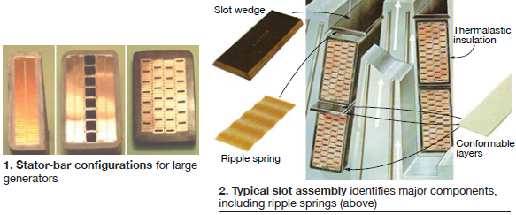
The composite tape usually is made up of a layer of glass or polyester (Dacron) tape, a layer of mica paper and perhaps a third layer of unwoven material. Total thickness of the tape is around 7 mils. Two bars then are assembled into a slot, as shown in Fig 2. (Very rarely generators have been made with one bar per slot.)
Many manufacturers have not used side springs, although they are becoming more common on large units. A top spring under the wedge is now very common, except on small units.
Resin evolution
The initial thermoset systems generally used polyester resins to replace the asphalt, great progress having been made with polyesters during World War II. Other components remained largely the same, mica flake with paper or cloth carrier.
But from the beginning two very different approaches were taken as to how the resin was applied:
- In the VPI process, resin is applied to the mica-taped bars through an individual bar vacuum-pressure-impregnation (VPI) process.
- Resin rich. Resin is in the mica tape, as applied to the bare bar.
In the mid-1990s, global VPI systems became popular for generators of moderate size—roughly rated 200 to 500 MW. Some of these systems have performed very well, but others have not. All are very difficult to rewind. These units are not a topic of this article.
The initial mica was the natural mica flake splittings, pretty much as the mica comes from the ground. As the high-grade natural mica became harder to obtain, a conversion to “mica mat” occurred. This mica is a “paper” made from lower grades of mica by a mechanized process that breaks down the mica into tiny “platelets” which are extremely thin. These platelets of mica are sufficiently thin that they have high ratio between width and thickness as did the original mica flake.
Polyester systems performed fairly well—if installed and supported well—but they were subject to difficulties: difficult to cure correctly, soluble in hot water even if well cured, limited temperature capability, limited mechanical capability. Result: By the 1960s, most OEMs were working on new epoxy-resin-based systems.
As each of the systems was developed, the manufacturers issued technical papers touting the merits of their new system (Refs 3-6).
Quality considerations
Manufacturers touted the properties of each new resin system. But in the opinion of the writer, the resin itself generally does not have much impact on the intrinsic quality and performance of the stator winding system—even if the groundwall system is made perfectly to engineering specifications. This (controversial) observation is based on considerations such as those that follow.
Consider that stator-winding performance depends on many parameters, some directly related the groundwall resin system itself, but most not. For example:
Design parameters directly related to quality of the groundwall system
- Cure of resin.
- Mica content.
- Mica tape backer material.
- Internal voids.
Stator-bar design parameters not directly related to groundwall system
- Magnitude of vibrational electromagnetic forces.
- Volts/mil design stress.
- Strand crossover insulation.
- Internal grading systems.
- External grounding system.
- External surface armor material.
- End arm grading.
Winding and connections
- Connection between grading and grounding systems.
- Uniform end arm spacing.
- Connection insulation.
- Slot vibration prevention system.
- Endwinding vibration prevention system.
- Connection-ring vibration prevention system.
Based on the complexities of the design of the various stator winding systems, is it possible, and likely, that the manufacturing facility and personnel will be able to meet the engineering requirements of the stator winding design.
Root causes of performance problems
Polyester groundwall insulation
Problems with groundwall insulation have been relatively few. In the very early days of the polyesters there were a few cases of cure failure that apparently permitted tape migration. Other lesser but important cure difficulties were associated with failure to obtain resin with correct components, resin pre-cure, incorrect cure temperature, and failure to adequately remove volatiles.
One OEM wedged its initial production of polyester windings with the same loose, clearance techniques as used with asphalt; these windings had severe and destructive bar vibration. This same OEM initially had bar cross-section issues, including dog-ear corners. This made reliable wedging of the bars in the slots impossible and resulted in numerous major winding problems.
At least one unit with water-cooled bars developed water leaks; the hot water destroyed the polyester groundwall insulation and resulted in winding failure. Also, polyester windings seemed vulnerable to high humidity which made drying of the windings difficult.
In general the polyester systems performed satisfactorily. However, the problems were sufficiently important as to cause early transition to the more stable and reliable epoxy resins.
Epoxy groundwall insulation
Epoxies eliminated most of the problems associated with polyesters. The groundwall concerns then focused on obtaining maximum performance from the groundwall. Brief comments follow on the parameters mentioned previously:
Curing of resin. If the cure is imperfect, obviously less than optimum mechanical and electrical capability resulted.
Mica content and tape backing material. The greater the uninterrupted mica content of the groundwall the better will be the electrical behavior. This suggests a thin carrier for the mica, and if a woven fabric such as glass or polyester is used, select a fine thread for the fabric.
Internal voids. These are difficult to avoid, particularly at the corners and between the bare bar and groundwall. Internal semi-conducting paints often are applied to address the latter.
Non-groundwall insulation
These problems are many and varied and carry low relationship to the groundwall system selected. Some have been experienced by all manufacturers. Some occur on only the VPI systems, some on only the resin-rich systems. Of the problems tabulated in the previous section, a few brief comments:
Magnitude of vibrational EMFs. Electromagnetic force is established simply by the design: It is essentially proportional to the armature reaction and inversely proportional to the number of slots. Armature reaction tends to increase with an uprate associated with cooling methods—air or hydrogen—and indirect or direct stator-bar cooling. And how hard the designer is willing to push the duties on the physical components.
Volts/mil. In a laboratory voltage endurance test, a good groundwall will be severely damaged by partial discharge and fail after many hundreds of hours at a stress greater than about 200 V/mil. Most of today’s systems are designed at less than about 70 V/mil and will not fail in 100 years. At 90 V/mil, “good windings” may eventually begin to fail electrically, but not until after many years of service.
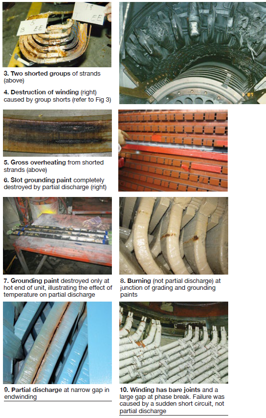
Strand insulation. The voltage between strands is very small, but important. At the crossovers it is reinforced by additional insulation. Still, insulation failures occasionally occur (Figs 3-5).
Internal grading systems. These systems can be simply paint applied to the bare bar, but can also be very complex. (The writer it is not certain that internal grading systems are well understood.)
External grounding system. These are always a semi-conducting paint applied directly or via tape carrier. But they are often a troublesome item, primarily on air-cooled generators (Figs 6 and 7). Some experts also are not sure that external grounding systems are well understood.
External surface armor material. Usually some “armor” tape is applied over the mica groundwall. If vibration occurs it will quickly wear off. Also, if a large-thread material is used, such as polyester, the threads may not fully impregnate and cause the condition shown in Fig 6.
End-arm grading. These materials perform the important duty of grading off the abrupt voltage discontinuity at the end of the slot grounding paint. The end-arm grading systems usually are not troublesome.
Connection between grading and grounding systems. Energy collected in the grading paint must be bled off to ground. This is done by connecting the grading paint to the end of the grounding paint. This connection often is not made well and gives a local peripheral mark on the bar. This is a burn (Fig 8), not partial discharge (PD).
Uniform end-arm spacing. If end-arm bar shape is not uniform and spacing between bars at the phase breaks is less than about 0.375 in., severe PD indications may be observed (Fig 9). But with mica in the groundwall, failure may never occur.
Connection insulation. The electrical voltage between series bars is small and the insulation here can be limited in capability—non-mica or even air. But the voltage between phase connections often is line-to-line and mica insulation, or a large air gap, is needed (Figs 10 and 11).
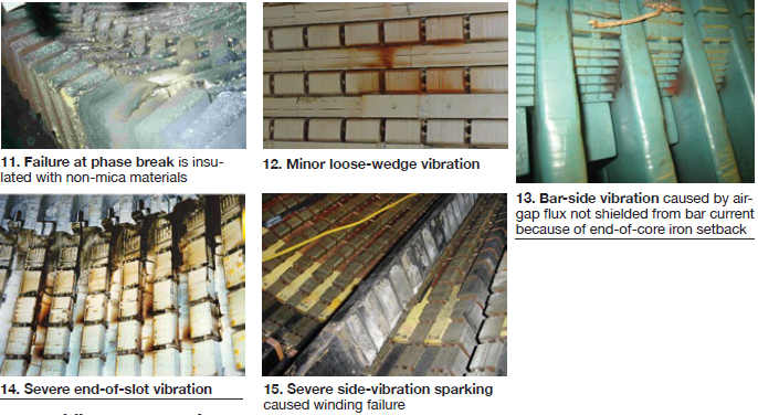
Slot vibration prevention. Slot bar vibration has been a relatively common deterioration and failure mechanism on thermoset windings (Figs 12-15).
Endwinding vibration is a common, widespread, and costly failure mechanism on thermoset windings. It is manifested in many degrees of magnitude (Figs 16-19).
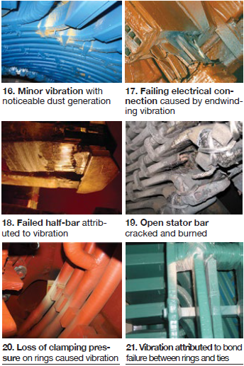
Connection-ring vibration is a common wear and failure mechanism with numerous causes (Figs 20 and 21).
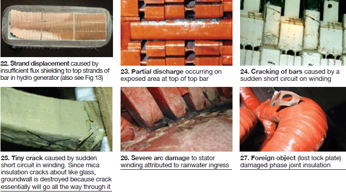
There are numerous other winding duty mechanisms that can cause deterioration and failure. Some are illustrated in Figs 22-27.
O&M recommendations
From an O&M viewpoint, all thermoset insulation systems are basically the same, although in a few important ways they are different from the soft asphalt systems. Thermoset windings are more vulnerable to cracking of the bar groundwall insulation from sudden short circuits, but more forgiving of over-temperature. Thermoset bars are vulnerable to cracking during winding installation.
A few cautions and special considerations relative to the thermoset windings are presented below. But O&M of the soft and hard insulation systems are not greatly different.
Operation
Nothing can be directly seen on the winding while the generator is in operation, and monitoring/ instrumentation capability is in general low. However, there are still important operational considerations, including the following:
Cleanliness. No insulation system likes contamination. On open, once-through cooling-air systems this can be a huge problem, depending on the local atmosphere. The only solution may be constant physical monitoring of contamination build up.
Even on TEWAC generators, contamination will often slowly build up, depending on tightness of the ventilation system, quality of filtering of the inevitable air ingress, and local atmospheric conditions.
On hydrogen-cooled designs, contamination can still occur, particularly over long periods of time, and primarily during outages. Depending on the nature of the material—for example, coal dust or brush-wear carbon—contamination can be an issue.
Cleanliness issues are greater on the rotor windings, but can be a problem with stator windings as well. It is something that efforts should be expended to minimize, but is likely to continue even under the best of efforts.
Moisture is a sub-set of cleanliness. While dirt contamination, and correction, can be well understood, moisture contamination, and its correction, may not be. On open and TEWAC ventilation systems, no prevention really is possible beyond avoiding leaking coolers. On hydrogen-cooled units, humidity can still be an issue with cooler leaks or non-functioning dehumidifier equipment.
Direct water-cooled stator winding. These systems require constant monitoring during operation to maintain water purity, correct water oxygen content, water pressure, performance of coolers, and detect water leaks.
Overload. System demands may call for overload of a generator. These situations should be limited because excessive load increases the electromagnetic forces on the stator winding as a squared function of current (load).
Asynchronous operation. Plant personnel may have little or no control in these situations, except during synchronizing. If the condition occurs at low power, no generator damage may occur. But if at high power, and persisting, total destruction of the generator may result.
Sudden short circuit. Except during synchronizing, the operator will have no control relative to short circuits. If synchronizing is off only a few degrees, no damage is likely. If a short occurs at 120 deg, maximum torque occurs and couplings may slip and other damage may occur. If the angle of synchronizing occurs at 120 deg, maximum forces on the stator winding will occur and the stator winding almost certainly will be destroyed.
Winding temperature instrumentation
The recommendation of the OEM should be followed carefully relative to monitoring and responding to winding temperature readings. This may prevent a minor problem from turning into a major, costly, and long forced outage.
There is an inclination to want to load the unit based on slot RTD/TC readings. On indirectly cooled windings these readings are very indirect and inaccurate. Read an amalgamation of the temperatures of the cooling gas, the core, and the bar copper through a thick thermal blanket (the ground insulation).
On direct gas-cooled windings, cooling gas often is measured as discharged from individual bars. These values are an important and reliable indication of winding performance.
On direct water-cooled windings, many designs measure the temperature of the cooling water from each individual bar, and these readings give a valuable monitoring of winding condition.
But on a large number of water-cooled windings, cooling-water temperature is measured as it is discharged from pairs of bars. Using the discharge water temperature and the corresponding slot RTD/TC temperatures, some limited intelligence can be derived as to winding condition. But interpretation of winding condition based on these temperature readings is complex and inaccurate.
Maintenance
A well-designed, properly manufactured, and properly operated generator is unlikely to require rewind in 30 years of operation, and maybe never. But it will require regular maintenance. The frequency of OEM-recommended maintenance has evolved in the last 25 years (Ref 7).
But regardless of maintenance frequency, and considering the discussion in the root-cause section above, some basic principles apply. They are:
1. No work should be attempted without a qualified crew and supervision onsite.
2. The quality of the work and the rate of progress will be expedited if all necessary tools and equipment are on hand.
3. Item 2 also applies to all needed materials and parts.
These three items can be a huge challenge. In particular, skilled workmen are limited in supply and availability. The availability of capable supervision is limited as well. Also, often those sent onsite, even by the best of OEMs and vendors, are not well qualified. The result can be costly in dollars and calendar time, and in quality of work.
In the case of failure root cause determination, if the lead investigative engineer is not highly skilled, incorrect determinations often have been reached and the result have been hugely negative in quality and cost.
Actual routine maintenance work constitutes a broad spectrum of often highly skilled effort. The work procedures have been documented by the OEMs and by others, and this documentation is broad and voluminous. No attempt has been made here to further document these procedures; but some special considerations are offered below on a few specific topics.
A good inspection by a qualified individual generally is the best assessment tool of a stator winding. It can reveal important information relative to deterioration associated with most of the conditions discussed previously in “Root causes of performance problems.”
Thus the importance of a skilled inspection cannot be over emphasized. This inspection will consume time, maybe a full shift or more, but it must be done and done by a qualified individual. Many technical papers have been written on this important topic and two books with chapters on maintenance are included under Refs 8 and 9.
Test. Some stator-bar deterioration mechanisms cannot be detected by inspection—for example, general deterioration of groundwall, internal PD, strand or bare-bar vibration or displacement, and strand and group shorts. (Turn shorts on a multi-turn coil will normally be detected by winding failure.) Detection of some of these conditions may be possible by available tests, the most important of the tests being over-voltage test (hipot). Many papers have been written on the subject (Ref 10).
Hipot is a powerful test, but is controversial because of possible winding failure, which would likely force a long outage for bar or winding replacement.
Power-factor test can be performed, although this test has limited usefulness in determining winding condition, in the opinion of some experienced individuals.
Partial discharge and electromagnetic interference (EMI) may also provide some intelligence on winding condition. Expert assistance may be needed to interpret test results.
Finally there is the low-voltage insulation resistance test—the “megger” test. Both resistance and polarization index readings should be taken at every convenient opportunity.
Other maintenance considerations:
- Robotic inspection without rotor removal is widely recommended by OEMs, and these devices can perform rather well in an inspection of stator core areas. They can also do wedge tightness test and ElCid core insulation integrity test. However, a robotic inspection is expensive and may indicate the need to remove the rotor anyway.
- Re-wedging of the stator winding is recommended where it is not needed. Judgement of wedge tightness can be very subjective—for example, manual test by inexpert individual, improper use of tightness test device, misunderstanding results of tightness device, etc. Re-wedging is expensive and time consuming, and can result in core and/or winding damage. Also, if only the end wedges are loose, only the end wedges should be replaced, not all wedges.
It is essential that a qualified expert is involved in any wedge tightness assessment decision.
- Stator cooling-water systems involve many components: piping, valves, controls, storage tank, filters, deionizer, coolers—and the stator winding itself. Close following of the OEM recommendations for operation and maintenance of these systems is highly recommended and can avoid costly repair (Ref 11).
Wrap-up
The foregoing discussion of stator groundwall insulation and stator windings systems is intended as a general summary only. It is by no means complete, or even comprehensive. The reader is referred to the several references provided below, and to references within those documents. Also, the website www.generatortechnicalforum.org has a large collection of references in “Resources.” The industry-wide library, open 24/7 at no cost to the user, is huge, variable in quality, and helpful if wisely and patiently used. CCJ
References
1. Clyde Maughan, “Asphalt Stator Winding Insulation,” IEEE/EIC, Baltimore, June 2017
2. Neil Kilpatrick, “Moisture Ingress and Storage Mechanisms In Large Generators,” Generator Users Group Conference, August 2017
3. C M Laffoon, et al, “A New High-Voltage Insulation for Turbine-Generator Stator Winding,” AIEE TP-51-121, January 1951
4. Thomas W Dakin, “Application of Epoxy Resins in Electrical Apparatus,” IEEE Transactions, December 1974
5. E J Flynn, C E Kilbourne, C E Richardson, “An Advanced Concept for Turbine-Generator Stator Winding Insulation,”AIEE TP-58-199, February 1958
6. N V Gjaja, C V Maughan, W R Schultz, “A Second-Generation Epoxy/Mica-Paper Insulation System for Large Turbine-Generator Stator Windings,” IEEE Transactions, 1975
7. Relu Ilie, “Advisory document reflects OEM’s changing maintenance philosophy over time,” Combined Cycle Journal, 2Q/2017
8. Greg Stone, et al, “Electrical Insulation, Insulation for Rotating Machines—Design, Evaluation, Aging, Testing, and Repair”, John Wiley & Sons Inc
9. Clyde Maughan, “Maintenance of Turbine-Driven Generators”
10. James Timperley, “AC High Potential Testing”, Doble Engineering Co
11. Clyde Maughan and Matthias Svoboda, “Water-Cooled Stator Windings”, Generator Users Group Conference, Las Vegas, November 2015
