
 It’s time to decide which conferences you will attend in the first quarter of 2019 assuming you haven’t already done so. If you’re involved in the specification, installation, operation, and/or maintenance of 501F gas turbines made by Siemens Energy Inc and/or Mitsubishi Hitachi Power Systems (MHPS), participation in the upcoming 501F Users Group annual meeting (see box at right) is particularly important.
The players in the service business are changing and their product/services offerings are evolving—oftentimes faster than you might think. It’s virtually impossible to do the job company management expects unless you keep up with that the suppliers are doing—especially the OEMs and their third-party competitors.
The all-volunteer 501F steering committee, headed by Cleco Power LLC’s Russ Snyder, has posted the agenda on the group’s website. This year’s program has the same compelling elements as the information-rich 2018 conference which ran four days and included the following:
- User presentations on issues identified in the fleet and solutions implemented, as well as on experience with upgrades to improve unit performance.
- User-only sessions promoting open discussions and short presentations by owner/operators on safety; compressor, combustion, hot-gas, inlet, and exhaust sections; rotors; auxiliaries; and generator.
- Special closed sessions by the major products/services providers serving this frame.
- Vendorama progam, comprising three-dozen half-hour technical presentations by third-party services providers, brings attendees up to date on offerings of primary interest to the 501F community.
- Vendor fair, following the Vendorama program on the first day of the meeting, gives users the opportunity to peruse the offerings of nearly a hundred manufacturers and services firms.
If you have never attended a 501F Users Group meeting, make the 2019 conference your first. You will learn things vital to your plant’s future success that’s not available in one place anywhere else. Chairman Snyder stressed, “Owners of 501F equipment certainly will leave the conference with a better understanding of their options in the marketplace for maintaining their equipment.”
Officers, directors of the 501F Users Group
President/Chairman of the Board: Russ Snyder, general manager, Southern Gas Fleet, Cleco Power LLC
Vice Chairman/Secretary: Carey Frost, program manager, Duke Energy
Board members: Blaine Gartner, outage supervisor and technical support, Xcel Energy
John Burke, O&M manager, Cottage Grove Power Plant (NAES Corp)
Brian Berkstresser, plant manager, State Line Plant (Liberty Utilities)
Dave Gundry, staff engineer, Xcel Energy
Dennis Winn, managing director, Klamath Energy LLC (Avangrid Renewables)
Ivan Kush, principal CT and Controls Engineer, Cogentrix Energy Power Management
Special closed sessions
There were four special closed sessions of either two or four hours each at the 2018 meeting to provide details on 501F performance-improvement solutions offered by industry heavyweights GE, MHPS, PSM, and Siemens.
These sessions were sandwiched between user presentations and discussion sessions on Tuesday, Wednesday, and Thursday to maximize participation. The special sessions all were well attended by owner/operators who asked insightful questions and actively participated in discussion opportunities. Presentations by PSM, GE, and MHPS can be accessed by registered users on the group’s website. Siemens posted its presentations on the company’s private Customer Extranet Portal. Unregistered owner/operators of Siemens power generation equipment can request access at https://siemens.force.com/cep.
General Electric
Recall that GE was a new entry on the agenda of the 501F Users Group annual meeting in 2017, having acquired that engine technology as part of its purchase of Alstom in late 2015. At the 2018 conference, engineers in the company’s cross-fleet solutions business unit updated attendees on their successes and upgrade products.
Key points that resonated throughout the presentations included the following:
- GE is a full-service provider for the 501F fleet and offers long-term service agreements as evidence of its commitment.
- Initial development activities focused on improvements and refurbishment. Today, the company is offering more advanced upgrades, ones based on GE F technology and its proven validation processes.
- Full engine spares are available.
- Dedicated engineering and service teams serve each frame in GE’s cross-fleet portfolio.
The status summary presented noted that GE has full upgrade capability in place for the 501F and that multiple outages have been completed. Plus, significant performance enhancements were said to have been implemented prior to the 2018 meeting.
A second phase of upgrades, planned for deployment in 2019/2020, and applicable for W501FA through FD3 models as well as the M501F, include a DLN combustor with additional fuel staging, full GE Advanced Gas Path (AGP) capability, and enhanced turndown with single-digit NOx.
A presentation on outage experience focused on the details of a W501FD3 combustion inspection that included integration of a wet-compression system.
In the generator portion of the program, the first example of GE’s capabilities was a generator in-situ robotic inspection incorporating a visual air-gap inspection and ElCID test. That outage window was only 48 hours. A second generator outage, this one for an AeroPac I commissioned in 2003, involved replacing the original pole-to-pole connector onsite to assure long-term reliability.
A fast stator rewind (22 days) was conducted on yet another AeroPac I—done during a turbine major inspection. This machine suffered misalignment of magnetic core segments leading to increased partial-discharge activity; the stator revealed significant indications of slot discharge. The owner opted for the rewind to avoid the increased risk of a three-month outage that would be required for stator/core repair should a failure occur.
The project included new stator bars incorporating the latest MICAREX insulation technology. Plus, lateral wedging with round packing to address misalignment of core plates and assure high-quality contact between insulation and the core.
Interesting to note is GE’s extensive experience in cross-fleet generator service, which pre-dates the Alstom acquisition by more than two decades. The company reports having completed nearly 500 jobs on generators made by 20 OEMs. Included are nearly 200 inspections and overhauls, more than 120 condition assessments, more than 75 rewinds (stator plus rotor, partial and full), etc.
Repairs. Focus of the first presentation in the repairs session showcased the company’s flexibility in dealing with “surprises.” The example given: Technicians were prepared to make repairs on IN738 first- and second-stage turbine blades, which turned out to be made of the nickel-based superalloy CM247 (VGP in Siemens speak) when they arrived at the shop. The configuration of these airfoils also differed from the design expected and they incorporated shaped diffuser cooling holes.
While unexpected, no “biggie.” Materials engineers and technicians implemented a process to characterize, inspect, and analyze the hardware received to develop the necessary repair solutions, which involved the development of coating, welding, and machining techniques. Photographs illustrated the work—including model creation, examination of the internal geometry, and metallurgical examination.
Inspection of the airfoils upon receipt at the shop revealed trailing-edge, platform, and weld cracking. Personnel likened the distress modes to those experienced with IN738 and GE F-class first-stage buckets.
The speaker explained the process developed for tip repair. Cracking extending below the tip cap was typical on these airfoils. In GE’s experience, CM247 is prone to cracking and it was important to develop a repair process that leveraged the OEM’s 7FA.04/FB experience.
A DVC (dense vertically cracked) coating system was developed and applied to the repaired turbine blades. Anyone under the mistaken impression that coatings and their application is akin to spray painting got a wake-up call at this point. The speaker explained how coating thickness is tailored to maintain the throat area, how air-masking is used to maintain cooling-hole diameter and shape, etc. GE believes the coating developed, and its application, will maintain past performance while improving durability.
The discussion moved to first-stage vanes, which had about 550 cooling holes. Challenges included (1) not having access to the OEM’s component flow targets and (2) relatively small cooling holes (nominal 30-mil diameter) drilled without coating collectors (counterbore). The GE team had to characterize incoming flow and establish final flow targets. A chart of airflow results for the first set of first-stage vanes repaired showed data points tightly clustered and within standard new-make tolerances.
Basket repairs also have required a significant investment to improve their durability with no adverse impact to part performance. The challenge here was that the 501F is a highly fragmented fleet with two OEMs participating, each having designs that have evolved over the years. The result: Several basket variants exist.
One example given was uncoated resonators that are prone to cracking. Another: An OEM coating configuration and system that offers little room for operational improvements. To extend component durability, GE conducted a program to analyze and test the original resonator configuration and make changes to accommodate coating application.
Parts and performance. The last segment of the GE session focused on improvements to second-stage blades and vanes, plus combustion testing in a high-pressure rig to support a combustor redesign and upgrade. Second-stage blades were said to suffer high fallout during repairs as well as early mortality.
Post-cast changes implemented by the GE shop included redistribution of cooling-air flow, additional platform cooling, and use of the company’s DVC thermal barrier coating. For replacement parts, GE touted the superior performance of its DS GTD141-1 material, a redesigned airfoil, and re-engineered root fillet and core.
GE’s second-stage vane also was designed to provide better performance than the OEM’s original airfoil. The benefits: a 1% increase in power output and a heat-rate reduction of 0.3%— based on the FD3 configuration. In addition, the promise of three 32k intervals. Key to the improvements, the speaker said, was improved air-flow distribution by conversion to a single cavity. The new vane is interchangeable/compatible with OEM hardware on a row-wise basis.
Combustor. Phase 1 combustor work included an upgrade to a Co-Cr-based wear coating and GE proprietary TBC; fuel staging (four fuel circuits and no transition-piece bypass; and more-forgiving weld geometry. The benefit of this effort: Combustors directly retrofittable in Siemens and Mitsubishi machines capable of 32k hours/1250 starts intervals to eliminate CIs.
Work underway on the Phase 2 flex combustor has the following goals: single-digit NOx, up to 20% additional turndown, and greater fuel flexibility, among other benefits. It will incorporate the same life-extension approaches as the Phase 1 combustor, enhanced fuel staging (late axial staging with fuel and air injected into the transition piece), and improved premixing by use of GE’s F/H-class integrated swirler/fuel injector.
MHPS
Team Mitsubishi’s program began with presentations on the company’s product portfolio, facility capabilities, key initiatives, and safety performance—as most OEM sessions do. The meat of the program for CCJ’s subscribers focused on rotor and exhaust-system issues and proven solutions offered by MHPS, plus the OEM’s engine performance and durability upgrades.
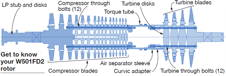
Presenters for this segment of the session were led by Scott Cloyd, recently promoted to chief engineer, gas-turbine service engineering, who opened the program with a primer on the inspection and care of W501FD2 rotors of value to both experienced attendees and first-timers (more than a third of the audience).
Cloyd shared the company’s experience gained during more than 200 comprehensive rotor inspections (CRI), stressing MHPS’s growing experience in its Savannah and Houston repair facilities. One of his primary objectives was to raise user awareness regarding CRI planning, common wear mechanisms, and torque-tube cracking and service support.
Before digging into CRI planning, Cloyd reviewed the operating history of peak, intermediate, and baseload engines. It was obvious from the data plot shared with the group that operating beyond MHPS’s recommended CRI intervals of 100,000 actual service hours or 12 years was akin to inviting problems. More than half of the engines in service are operating outside recommended inspection intervals.
He noted that corrosion was of particular concern to low-hours units, saying that some machines may go 12 or more years before their first hot-gas-path (HGP) inspection. Corrosion occurs primarily because of condensation in a cold rotor cycling in and out of service while subjected to ambient-temperature and humidity changes.
The condition is exacerbated when wear from blade rock reduces the contact area between the blade and disc fir-tree serrations. This concentrates stress at the top-most serrations; defects in the serrations below can amplify stress in the already highly stressed locations.
Cloyd said CRI results should be able to answer this question for the engine owner/operator: Can rotor components operate until the next scheduled interval? A pre-CRI assessment will help determine inspection scope and assist in parts planning and availability. It is intended to identify rotor component concerns, determine the state of material degradation, and characterize the wear of turbine-disc root serrations.
Historian data are important to the accuracy of any rotor assessment. Trending of rotor ageing characteristics improve component life predictions. This analysis should begin at the turbine inspection (TI) prior to the CRI and provide a continual stream of information to planners. Depending on the results of the pre-CRI rotor assessment, the engine owner might want to have a spare rotor on standby for a possible swap-out to minimize outage duration.
Cloyd suggested the following inspections be performed at the TI before the CRI to trend rotor health:
- Visual and dimensional checks.
- Corrosion-pitting inspections to measure size and depth.
- Hardness measurements.
- Blade shroud gap and platform gap checks.
- Grain-structure replication and anslysis.
- Turbine-blade root serration wear.
In your pre-CRI investigations, remember that dental molds are valuable for characterizing blade groove wear (high turning-gear hours can result in uneven wear and loading) and serve as a historical reference point for future evaluations. Molds of the turbine-disc root serrations are excellent for evaluating the severity of corrosion pitting.
Cloyd next outlined key aspects of a CRI recommended by Mitsubishi. Below is a list the components that should be checked, what should be investigated, and the inspections typically called upon to assure an accurate assessment. The rotor cross section provided may prove useful if you have limited first-hand knowledge of the W501FD2.
- Spindle bolts can suffer fatigue or fretting wear. NDE of bolts, lands, and threads can point to possible problems.
- Turbine-disc cooling-air passages can become clogged. Find visually and clean.
- Turbine-disc blade serrations can suffer corrosion, wear, and fatigue. First step is surface cleaning and scale removal. Then NDE contact surfaces, measure blade rock, and evaluate pitting. Blend as needed.
- Curvic clutch may experience wear, which can be found by visual inspection plus checking metal-to-metal contact.
- Compressor and turbine discs are susceptible to corrosion, cracking, pitting, creep, and/or hardness changes. Conduct visual inspection and NDE all contact surfaces, perform hardness checks, and take replicas.
- Journals are susceptible to wear, scoring, and/or cracking. Dimensional and runout checks point to certain problems; visual checks can identify scoring and pitting. NDE is relied on as well. Machining corrections are made as needed.
Cloyd had users’ eyes glued to the screen with his photos of turbine-disc corrosion, wear and tear attributed to blade rock, etc.
He then reviewed typical CRI findings and repairs, including:
- Peening and machining of compressor-disc spigots to remove fretting and restore proper interference.
- Root end-face cutbacks on compressor blades to reduce the potential for diaphragm rubs caused by locking-groove wear.
- Shot-peening of compressor-blade grooves to remove scale which otherwise would accelerate wear of the root coating.
- Removal of debris from air-baffle grooves to mitigate baffle-plate wear.
- Blending-out of indications and signs of wear.
Before moving on to torque-tube cracking, Cloyd addressed air-separator health. He said fretting often is observed on the air-separator contact face and that restoration of this surface is critical to reduce the risk of crack propagation. Cloyd also reminded the group that a shim can be used at the torque tube-to-air separator flange to restore pre-load.
Torque-tube cracking. Recall that the torque tube on 501F engines joins the compressor and turbine sections of the rotor. Cloyd said three W501Fs were reported to MHPS as having experienced forced outages attributed to vibration events caused by through cracks in the torque tube. The cracks were concealed by the air separator (figure provides clarity). He added that no M501Fs have had this problem.
One failure was described by a second speaker directly involved in the analysis. Deck-plates personnel closely monitored increasing vibration levels recorded on a W501FD3 over a 14-hr period. As the vibration approached alarm limits, the engine was shut down for investigation. Polar plots indicated there was a change in rotor stiffness, which could have been caused by a cracked air separator, cracked torque tube, or turbine or compressor bolt failure. The highest vibration level was recorded at the exhaust bearing.
A diagnostic strategy was defined to identify the cause of the vibration-trend change with the goal of minimizing outage duration. A borescope inspection revealed no irregularities and a cover lift showed the air separator to be in good condition. But ultrasonic inspection of the torque tube identified a large crack; the indication traveled 60 deg around the torque tube. More accurate shop measurement recorded a crack 24 in. long and 90 deg around the torque tube.
The field work associated with this project was challenging and timing was critical given the forced-outage situation. Previous work on the unit included modification from FD2 to an FD3 with a single-piece exhaust to address cracking issues with the original exhaust system. Work-arounds for MHPS field-service personnel included limited overhead crane travel and the lack of special tooling to handle the SPEX.
Mitsubishi provided tooling for rotor support and bearing removal, as well as skids for removal of the exhaust spacer, manifold, and cylinder to enable a conventional rotor lift. Rotor extraction was facilitated by removal of all compressor blades which were inspected and blended as necessary. At the time of the meeting the rotor was in the Savannah shop for a CRI, torque-tube replacement and a root-cause analysis of the torque-tube crack.
What the speaker revealed based on rotor disassembly and early shop work was that there were actually two cracks—the 24-in. crack and another one of about 4.5 in. in length. The second crack formed after the first had propagated. A review of cracking of a torque tube of similar geometry on a W701F suggested the root cause might be corrosion-assisted low-cycle fatigue with propagation by high-cycle fatigue (rotor bending from gravity). Be sure to attend the upcoming meeting to learn more.
Based on this and previous work, the speaker suggested a cover lift as part of the pre-CRI and phased-array inspection of the torque tube to detect the presence of a crack before a forced outage occurs.
MHPS presented its solution for the torque-tube and air-separator failures facing some owner/operators, including the company’s 501F3-style torque tube and bolted air separator for the W501F machine. The first such arrangement sold is installed, having met all quality requirements on its balance run.
Other upgrades recommended by the speaker included root springs to reduce disc wear from blade rock during long periods of turning-gear operation; plus coating of compressor rotor discs to protect against particulate matter in the flow path, as well as corrosion.
Ramy Massoud followed Cloyd with an overview of MHPS technology flow-down for gas-turbine durability enhancement and improved engine performance. Massoud shared that at the time of his presentation these upgrades had logged more than 6.8-million hours of operation and 60k starts on Mitsubishi machines.
Pictures of both hours- and starts-based fleet-leading W501F hot components in excellent condition were shown on the big screen at the front of the meeting room. None required more than light repairs—including the Row 1 vanes and blades. There was zero fallout. A user in attendance confirmed these results. MHPS validation methodology supported an interval extension for all turbine components to 32k hours/1200 starts.
Massoud then provided an update on MHPS’s latest F-class turbine upgrade, which was derived from M501J technology with optimized cooling, advanced and thicker TBS, as well as an optimized wall thickness. An F-class case history confirmed both output and heat-rate expectations were exceeded and that the 32k-interval goal was achieved.
Pictures showed hot parts in very good condition, with no visible coating chipping or cracks. MHPS is confident that the reliability of these high-performance parts will be at least equivalent to the company’s standard turbine components.
Massoud’s portion of the program concluded with an overview of the OEM’s TOMONI© solutions and a digital analytics road map. The company’s strategy is to work with key software partners having deep experience in critical areas while leveraging MHPS’s value-added experience working with big data and powerplant operations knowledge.
Matt Grysko wrapped up the session with an overview of the MHPS exhaust cylinder and manifold. Design features and operating experiences were shared. No abnormalities were evident in the photos taken at up to 83k EOH.
Grysko pointed to aspects of the MHPS design that addressed each of the W501F failure modes experienced in the fleet. These included improved/aligned materials, optimized mechanical loading, and more strategic cooling. The upgrades allowed for the relief of stresses and reduction of temperatures conducive to the cracking identified with the existing design. Photos of an installation in progress confirmed the availability of a drop-in solution that did not require changes to auxiliary piping or the foundation.
PSM
PSM’s four-hour session incorporated presentations on the vendor’s product line, combustion options, airfoils and upgrades, exhaust system, and the 501F rotor, as well as other topics. Global Product Manager Brian Micklos got the ball rolling with a review of 2017 accomplishments—including the following:
- PSM’s first two exhaust-system installations. Details are provided in a separate article on p 46, “Repairs never-ending? Replace problematic exhaust systems.”
- Replacement in-kind of targeted rotor components as of part of refurbishment—including some discs.
- Rotor component procurement.
- Achieved 33k equivalent baseload hours (EBH) without repair on transition pieces and baskets.
- Demonstrated turndown to less than 40% of rated engine capability, with inlet bleed heat.
Next, Micklos discussed the interchangeability of PSM parts—both standard and upgraded—with original equipment stating that all of the company’s hardware is set-wise compatible for applicable frames. A few of the examples he presented included these:
- Compressor. Replacements for all FD components.
- Combustor. Full drop-in system or component replacement, gas only and dual fuel. FlameSheet™ for both W501F and M501F featuring sub-9-ppm NOx operation.
- Turbine. All major components for the W501FC-FD2 and M501F3 models, plus the first three stages for the W501FD3 (fourth stage in process).
- Exhaust. W501FC-FD2 drop-in cylinder (includes new manifold front flange); FC-FD2 drop-in manifold (but only available with PSM exhaust cylinder).
While most users were generally familiar with the company’s W501FC-FD2 and M501F3 hardware, and to some degree with its W501FD3 components, several were surprised to learn that it also offered some W501F4/F5 hardware as well—including transitions and fuel nozzles, Gen4 baskets, FlameSheet, and Stage 4 turbine blades.
Discussion of interval and life expectations for PSM hardware had attendees focused on the speaker. Here’s what he said:
- Concerning the rotor and compressor, no maintenance is expected until the second major outage from installation.
- Concerning the combustor, maintenance intervals are 25k hours/900 starts, with a four-interval lifetime for all parts. Components incorporated into the company’s GTOP6 (Gas Turbine Optimization Program) upgrade—roughly the equivalent of a Siemens FD3 upgrade for performance, but executed in a smaller scope—can have a maintenance interval of up to 32k/900.
- Regarding GTOP6, note that the 25k version of this upgrade allows a 15-MW simple-cycle increase in output and a heat-rate reduction of 3.5% compared to that for the standard W501FD2 combustion system. Opting for 32k hours reduces the output gain to 7 MW and the simple-cycle heat-rate benefit to 1.5%.
- GTOP7, planned for release in 2019, is expected to boost the performance improvement for the 25k interval to 20 MW of simple-cycle output and plus a 3.8% reduction in heat rate. For the 32k interval, the benefits are 8 MW more output and 2.1% lower heat rate.
- Concerning the turbine, first-stage parts are designed for two intervals of 25k/900, second stage for three intervals of 25k/900, third and fourth stages for two intervals of 50k/1800. GTOP6 extends those intervals to 32k/900 and 64k/1800.
Hardware experience was a perfect sequel to the interval discussion. Component durability is confirmed by fallout rates of 0% for all critical hot-gas-path (HGP) parts—except for PSM’s Gen 2 and Gen 3 baskets and Gen 3R1 blades, which suffer about 10% fallout. Fleet leaders for transition pieces and pilot nozzles are now in their third intervals of 25k EBH.
Combustor products and experience was the next topic. PSM has three basic offerings here: (1) Standard drop-in 501F combustor; (2) Drop-in combustor plus inlet bleed heat (IBH) plus AutoTune for automatically keeping emissions and combustion dynamics within specified limits under varying ambient conditions; and (3) FlameSheet.
The first two maintain NOx and CO emissions to less than 25 ppm between the lower operating limit and 100% of the full-load rating when burning liquids-free gas; FlameSheet restricts emissions of both pollutants to less than 9 ppm on liquids-free gas. All three can meet 42 ppm NOx (wet) on liquid fuel. Turndown capability of the standard combustor extends to 55% to 65% of rated load, with enhancements (Option 2) to 45% to 55%, with a FlameSheet drop-in to 30% to 40% using the standard firing curve.
A big benefit of FlameSheet, in addition to extended turndown capability, is greater fuel flexibility compared to traditional OEM offerings. This is particularly beneficial both to plants burning shale gas and LNG, which may have a wide range of varying constituents, and to those with access to off-gases from industrial processes.
For the first two combustor offerings above, PSM specifies a minimum of 85% methane, no hydrogen, and a maximum of C2+ constituents; plus, it restricts the variation in Modified Wobbe Index to 5%. Compare this to the specs for FlameSheet: a minimum of 40% methane and up to 40% hydrogen, 40% C2, 20% C3, 10% C4 to C6, and 30% inerts.
Results from the first two installs of FlameSheet in 2015 (Eastman Chemical Co, Longview, Tex) were reviewed to confirm stated performance. The data: Turndown confirmed to 40% of rated load with NOx emissions below 5 ppm at 40% and less than 7 ppm at 100%. CO was less than 9 ppm at 40% load and about 1 ppm at 100%. Part-load efficiency was measured at less than 127% of the full-load number; goal was 130%. Startup visual emissions were eliminated, reducing exceedance reporting by 200 reports annually.
Important: FlameSheet enables Eastman to keep its units operating year-round because of their increased turndown. Also, it gives the company the potential to burn waste fuel streams rich in hydrogen.
Drop-in combustion-system experience, a/k/a market penetration, was summarized in one slide. About 70 sets of pilot nozzles had been sold as of January 2018, the speaker said, with fleet leaders above 60k fired hours and 1250 fired starts. Total fleet experience was closing in on 2-million EBH.
For transition pieces, the numbers were about 95 sets sold, fleet leaders at more than 60k fired hours and 1250 fired starts, and fleet experience at 2.2 million EBH. Extended-turndown combustion baskets have been installed in more than 30 engines, with fleet leaders at 33k fired hours and more than 550 fired starts. The numbers for support housings: About 20 sets sold with fleet leaders at 31k fired hours and more than 450 fired starts.
Session focus migrates to the rotor. PSM reported that, at the time of the 2018 meeting, it had completed two rotor lifetime evaluations and another was in progress. The company also had completed rotor lifetime evaluations for two Frame 6B engines and one 7F.
Experts explained how rotor lifetime evaluations were conducted. They began by listing the inspections required: MPI/FPI, eddy current, and ultrasonic; plus, a metallurgical evaluation. Using these techniques in a set of overlapping inspections the following key failure modes can be identified and all defects found:
- Surface defects.
- Forging/volume defects.
- Compressor-bolt inspections.
- Torque-tube nut groove.
- Air separator goose neck.
- Turbine-disc scallops and small radaii.
PSM’s portable lab permits onsite hardness and microstructure review in a single shift using two technicians. Grinding and polishing prepare the metal for imaging using a Keyence microscope. Hardness testing is done in locations near where microstructural reviews are conducted; multiple tests are conducted at a given location and the results are averaged.
Eddy-current inspections are conducted in bolt holes, bores, and critical locations. No defects are allowed. All components—disk bores, webs, slots, attachments, posts—are fully inspected using a combination of conventional and phased-array ultrasonic methods.
The speaker stressed that a 501F rotor assembly contains more than 200 parts and all must be flawless.
Siemens
The Siemens session began with a presentation highlighting some of the successful programs the company has in place to promote awareness of, and bring attention to, safety. Siemens’ safety record validated the success of its efforts.
A comprehensive presentation on technical solutions and improvements followed. Siemens speakers discussed technical issues experienced by the F fleet over the last several years and then provided details on the improvements implemented to address them.
Next came presentations on repair technology development and technology innovations. They covered some of the many tools Siemens is investing in and developing to pave the way for the future in repair-process improvement, cost-reduction initiatives, additive manufacturing, materials development, coatings, inspections, measurement accuracy, etc.
An update on current developments in Siemens’ robust digital portfolio of energy services—including cybersecurity offerings—followed. The solutions presented (access the list on the Customer Extranet Portal) can be tailored to each customer’s unique needs and operating conditions.
Siemens concluded the session with a comprehensive overview of its product portfolio for F technology. In some combination, the available products are designed to offer safety, power, efficiency, operating and starting reliability, availability, emissions improvement, flexibility, maintenance ease, and interval extension—depending on the particular needs of an owner/operator, plant, or site. Statistics on implementation and experience with the upgrades were included and speakers encouraged users to contact their platform teams for further discussion. CCJ