Turbine Tip No. 2, from the Dave Lucier’s PAL Turbine Services O&M solutions library, applies to General Electric Frame 5 models K-LA and M-P, and early 6Bs, 7Bs, and 7Cs, equipped with Y&F fuel regulator and Speedtronic™ Mark I, II, and IV controls.
Overfiring a gas turbine during startup can be a serious condition, particularly when the engine is cold. As a GE gas turbine fires and warms up, fuel flow is controlled by the average exhaust temperature—called Txa. During the subsequent acceleration period, the starting means (diesel engine or electric motor), assists in bringing the turbine rotor up to rated operating speed.
On legacy units, as the coupled rotor passes through a mid-range zone, compressor air flow and pressure may be insufficient to maintain Txa under 950F, as recommended by the OEM. If your control system is incapable of limiting fuel flow to prevent the exhaust temperature from exceeding 950F, be advised that GE provided for manual control of its early gas turbines (years from 1960 to 1980).
In the decade of the 1960s, GE gas turbines used the Young & Franklin fuel regulator for engine control. In the early 1970s, Speedtronic became the electronic control and protection system of choice. In this 20-year span, the OEM provided methods for “overriding” the automatic controls with a manual feature on its gas turbines.
In Fig 1, an operator is shown “thumbing” General Electric Manufacturing Co’s (GEMAC) 70TC programmer to control exhaust temperature during acceleration of a Frame 5L gas turbine. This action limits Txa temporarily, by manually controlling fuel flow to the combustors. Once the temperature has “crested,” at about 2200 to 2400 rpm, the operator can release his thumb, allowing the timer to run up to its 100% stop.
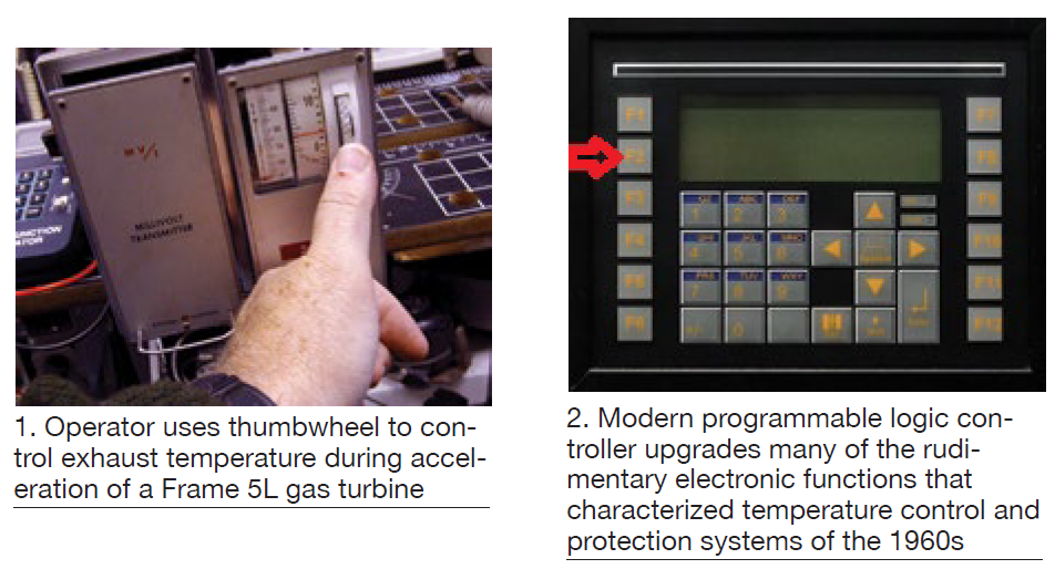
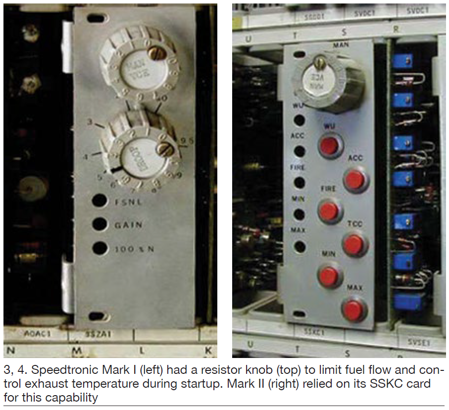
Several MS5001K-LA gas turbines installed in the mid-to-late 1960s have had their legacy temperature control and protection systems replaced/upgraded with a programmable logic controller (PLC), like the PAL GEMAC in Fig 2.
Recall that the technology of the day in the post Northeast Blackout era (November 1965) was early integrated circuitry. The operator-friendly PLC can perform many of the electronic functions from 50 years ago easier and faster. Example: Manual override with the PAL GEMAC is provided with the F2 function key (arrow in Fig 2)—much simpler to use than the thumbwheel feature it replaced.
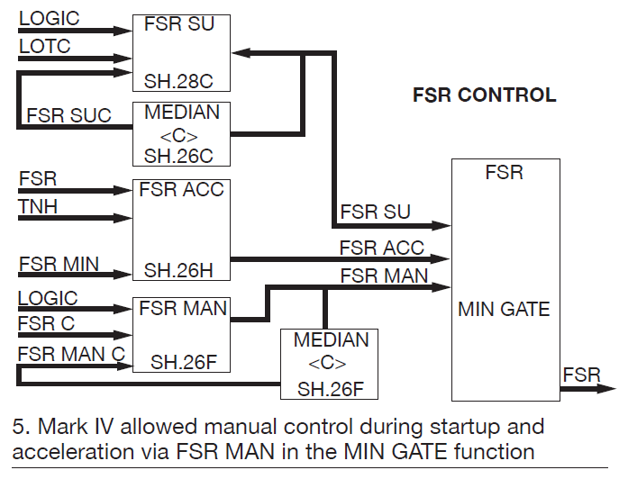
Beginning in the 1970s, Speedtronic Mark I controls had a manual resistor on the speed control circuit board called SSZA (Fig 3). It is the upper resistor knob in the photo—named MAN VCE for manual, variable control electronic, or minimum fuel command. Turning the knob to the right (clockwise) decreases the fuel control voltage, thus fuel flow. An alarm will sound. Fig 4 shows the later version of Speedtronic, the Mark II. Its MAN VCE is located on the SSKC card. The audible sound can be silenced, but the annunciator flag remains until the knob is returned to normal.
Case study. A user recently had a problem starting his MS5001N, equipped with Speedtronic Mark I controls. When the turbine reached approximately 1900 rpm the unit tripped because the average exhaust temperature exceeded its allowed operating limit of 1000F. Subsequent trips made the problem particularly difficult to diagnose. The diagnostics team believed the turbine had to continue operating, so the system could be observed and analyzed.
Plant personnel were unaware of the manual control option and the reasons why GE had installed it. The site engineer was advised to turn the MAN VCE knob clockwise during acceleration (at 1700-1800 rpm). Yes, the alarm sounded. VCE was limited temporarily, so troubleshooting could begin. In this case, it was desirable to run at a safe speed at an exhaust temperature less than 900F. I&C sleuths determined that a 240F comparator “oven” was defective and had to be replaced.
Even modern GE gas turbine control systems (circa 1980-1985), like the Speedtronic Mark IV (Fig 5), provided for manual control during turbine startup—should it be needed. Refer to FSR MAN in the MIN GATE function. During startup and acceleration, manual control is possible with this function, though on later-model gas turbines its use is less likely. The MIN GATE looks at all inputs and selects the one that “calls for” the lowest fuel flow. In this case, MAN VCE can be that one.
On a new Frame 5 gas turbine, the average exhaust temperature was expected to “crest” at about 810F approximately 3 minutes and 20 sections into the start cycle (red arrows in Fig 6), when the turbine was at about 80% speed (nominally 4000 rpm).
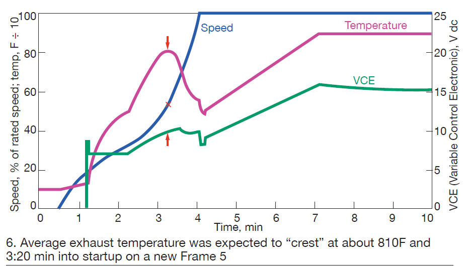
Bear in mind that if the temperature drifted too high, the turbine might trip on over-temperature. The operator could limit VCE manually (read 10 Vdc on the right vertical axis) to prevent a trip until the air flow and compressor discharge pressure increased to cool the exhaust. Perhaps a MAN VCE setting of 9.5 Vdc might work better in this case. Later, the ACCE VCE limit could be recalibrated lower to this same limit.
In conclusion, many legacy GE gas turbines have ways to temporarily control fuel flow (manually) to the combustors. During startup, it may be necessary to manually limit fuel flow until rotor speed passes through a critical zone (1800 to 2300 rpm). GE provided the controls to assist the operations team in troubleshooting.