
The 2020 Digital Conference hosted by the 7F Users Group was the first web-based annual meeting conducted by a user group serving owner/operators of gas-turbine-powered simple- and combined-cycle generating plants in the US. Most of nearly 700 registered users believed the 13- day event, conducted over five weeks from June 16 through July 16, exceeded expectations— except possibly for some hiccups identified with the virtual vendor fair on the first two days of the event.
The conference was viewed as highly successful by CCJ’s editorial team. The content was compelling and easy to access; plus, no travel required, no negative budget impact. The Q&A following the presentations was more robust and efficient than at most face-to-face (F2F) meetings, which can have “dead” time as microphones are passed around the room and attendees gravitate to email.
A major benefit of the virtual 7F meeting was that most of the proceedings were recorded and are available to users (details in the sidebar) who might have been called away from a session they had planned to attend, or want to listen to a given presentation again to confirm details.
The downside of virtual conferences, of course, is that there’s no personal interaction with colleagues, which can be extremely valuable. Looking ahead, the editors think the format of future user-group meetings may have both online and F2F components.
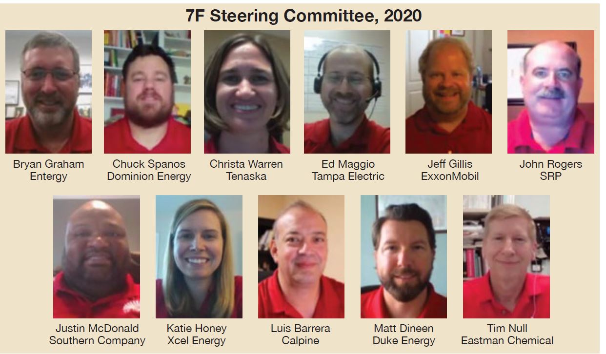
A big “thank you” is due members of the 7F Steering Committee (photos) for developing the technical program and for dedicating the considerable amount of personal time required to transition from a F2F format to a virtual one. There was no roadmap for doing this. It took countless hours of experimenting and rehearsing to arrive at a format that would meet expectations. Note that screen shots of committee members substitute for the traditional group photo this year.
To dig deeper
A broad range of topics was addressed at the 7F User Group’s 2020 Digital Conference. You may have missed one or more presentations of interest, or might want to listen to a particular one again. This is possible.
Dig deeper into any of the topics covered in this report by visiting the Power Users Presentation Library, where slides and/or videos are posted for your professional development. However, you must be registered on the website for access. Simple process if you don’t already have a “library card:” register online now.
Presentations by owner/operators
Safety
The Safety Session on the first day of the meeting, chaired by Dominion’s Chuck Spanos, followed introductory remarks by the 2020 Steering Committee Chair Matt Dineen of Duke Energy. Presentations addressed two of the industry’s hottest safety topics: Hex chrome and Covid-19 mitigation.
Hex chrome: You may be aware of it but how much do you really know? The well- organized hex-chrome presentation is ideal for a lunch-and-learn session in the plant break room to be sure all personnel are on the same page with regard to this issue. It begins with a review of the health effects associated with exposure and provides guidance on exposure limits. Control measures to protect workers—respirators, protective clothing, increased ventilation, adjustments in the way a task is performed, etc—follow.
Cleaning methods are an important part of the presentation. Surfaces contaminated with hex chrome typically must be cleaned by HEPA-filter-equipped vacuums or by wet methods, such as wet sweeping or wet scrubbing. GE does not recommend use of dry methods for contaminant removal—especially wire brushing and compressed air—because they may cause the residue to become airborne. Also, waste material or debris contaminated with hex chrome must be collected and disposed of in sealed, impermeable bags or other closed, impermeable containers.
The OEM’s Product Service Safety Bulletin (PSSB) 20180709A-R4 and OSHA 3373 were recommended information resources. The first alerts against the use of anti-seize compounds that contain calcium and have the potential to result in the formation of hex chrome when applied to chromium-containing materials and exposed to elevated temperatures. The anti-seize compounds recommended for Frame 6, 7, and 9 gas turbines are Kluber paste HEL 46-4500 and Bonderite L-GP GP460.
The speaker said he was not aware of any reported hospitalizations tied to hex-chrome exposure, which is not characterized by an “acute” attack. However, health-related effects could show up years later. A person wouldn’t necessarily know if he or she was contaminated by hex chrome or inadvertently ingested it. Those users with a nuclear background might see similarities with inadvertent exposure to radioactive material.
Covid-19: Is there anything else we should know, except accurate facts? The speaker developed slides on what had been reported at the time of the meeting: symptoms, groups at high risk for severe illness, precautions, contact guidance, and employee protection. Nothing new here, and to the speaker’s credit, he didn’t spend valuable time rehashing this material. Instead he focused on a so-called outage planning heat map and changes his colleagues might consider to their outage execution plans for mitigating exposure.
The heat map described in the presentation and available to you on the Power Users website identifies “at-risk” outages and mitigations and the value of holding regular meetings to update outage plans.
Lessons learned during recent outages suggested the following changes to consider regarding outage execution to avoid exposure:
- Segregate shift teams. Use phone or other digital means to communicate during shift turnovers. Provide a separate trailer for each shift.
- Maintain social distancing during morning toolbox talks and move them outside (weather permitting). Strive to conduct meetings in 15 minutes or less.
- Eliminate weekly group safety meetings; move them online if need be.
- Schedule breaks in a manner to minimize personnel contact.
- Organize work on the deck plates so only necessary personnel are present and try to maintain the suggested 6-ft distancing to the degree possible. If a “safe” distance cannot be maintained, issue additional PPE to compensate.
- Limit one person per row of seats in company vehicles.
- Stress increased personal hygiene. Add hand-wash stations and increase cleaning frequencies in common areas as necessary to achieve goals.
- Monitor the temperatures of workers as they enter the site.
- Be aware of the increased potential for heat-related stress created by wearing extra PPE.
Perhaps the most important lesson learned: Day-to-day productivity has not been impacted significantly by implementation of the above rules. The biggest concern for anyone with outage responsibility: The chance of an entire job being shut down if someone in the workforce were to test positive for Covid-19. Be vigilant, maintain strict adherence to the health aspects of your outage plan.
Combustion
The first presentation in the Combustion Session, chaired by John Rogers of SRP, reviewed one user’s experience with FlameTop 3.0™, which combines the performance improvements offered by PSM’s Flamesheet and G-Top 3.0 products.
Project update on FlameTop 3.0. The shortlist of Flamesheet performance goals/results:
- Confirmed: Turndown to 50% output while maintaining permitted NOx and CO emissions of less than 9 ppm each; achieved turndown to 40% output.
- Confirmed: Less than 5 ppm NOx at 40% output, less than 7 ppm at full load.
- Confirmed: Less than 9 ppm CO at 40% output, about 1 ppm at full load.
- Confirmed: Efficiency equal to or better than gas-turbine efficiency prior to upgrade.
- Confirmed: Efficiency at 50% load less than 130% of the full-load efficiency; less than 127% achieved.
- Confirmed: Elimination of visible emissions on startup. The shortlist of G-Top 3.0 performance goals/results:
- Confirmed: Maintained all Flamesheet achievements.
- Confirmed: Increased gas-turbine output by 5.79%.
- Confirmed: Decreased unit heat rate by 71%.
- Confirmed: Eliminated seasonal tuning.
- Evaluating: Longer maintenance intervals made possible by different modes of operation.
After FlameTop 3.0 installation, the 2 × 1 cogen plant, powered by unflared 7241 engines, experienced several engine trips triggered by the flashback protection system. Suspected issue: Increased sensitivity to fuel-gas-skid condensate formation leading to autoignition. Combustor mods implemented in November 2019 to eliminate the problem were successful. FlameTop 3.0 was said to have allowed the cogen facility to better align with the host site’s steam and electrical demands. Satisfied customer: The second unit will be converted to FlameTop 3.0 during an upcoming hot-gas-path inspection.
Lessons learned during commissioning. Three valuable experiences were shared by a user who was involved in the commissioning of two 7FA.04-powered 1 × 1 combined cycles early this year. Both units are equipped for dual-fuel firing with DLN 2.6+ combustors, and have bypass dampers. Fired hours on the units just ahead of the meeting were 3300 (68 starts) and 3100 (95 starts). Run profile: Baseload with automatic generation control (load following).
The speaker urged attendees planning a commissioning to understand how their unit’s warranty handles newly issued TILs (Technical Information Letters) to save aggravation and money down the road. His units were able to incorporate most TILs during the construction and commissioning process. However, some TILs were assigned after the units were received and would have required significant disassembly for compliance. Suggested work was postponed for a future outage.
The need to verify that no foreign materials remain in the machine when it is buttoned-up for operation was stressed. The speaker said, “The seemingly most-simple task can have severe consequences if not performed with rigor.”
During inlet-guide-vane calibrations in preparation for performance testing of one unit, damage was found on several R0 blades. Inspection revealed that a ball of duct tape had been left in the inlet and was ingested. A dozen blades were damaged and blended; there were no vibration issues afterwards. However, tape residue had reached the seventh stage and was not completely removed by water washing.
Commissioning of one unit on oil proved difficult. It could not be tuned when in the liquid-fuel mode because of high exhaust spreads. Note that these units are equipped with pressure-atomized liquid-fuel systems (acronym is XAA), which eliminate the need for atomizing air. No coking has been experienced, but operating time on oil was less than about 50 hours for each gas turbine. The user said more run time was required to fully evaluate the reliability of the liquid fuel system.
XAA is an emulsification system that mixes liquid fuel and water ahead of the end cover. The speaker reported that water injection starts at about 40 MW following a pushbutton start on oil only. Water is used to flush the fuel system after burning oil.
Learn how GE engineers found and eliminated the gremlins responsible for the operational problem by accessing the presentation on the Power Users website. To learn more about this system, request GEK 121513 from the OEM.
Combustion polling results guide discussion session. The 7F was the first user organization to use electronic polling as a method for guiding and contributing to topical discussions, according to the editors. Tenaska’s Christa Warren, the 7F Users Group’s vice chair for 2020 makes liberal use of polling in her interactions with the group. She led a brief discussion session on a couple of combustion issues that appeared on agendas of previous meetings to see if there was anything new to talk about.
One subject was fuel-nozzle damage, which had been experienced by 56% of the attendees. As for cause, 28% of the respondents named fuel contamination; “other” and “unknown” received 64% of the votes. Warren put up photos of fuel-nozzle damage on the screen to get some feedback. One user said that at least some of the damage shown likely came from burning because the flame was not detached from the nozzle like it should be. Another offered that proper use of atomizing air is critical to nozzle damage control. Yet another said most damage he has seen was on PM2 and PM3 nozzles. High NOx and ammonia were said to be key indicators of fuel-nozzle damage.
Another topic was the adverse impact of cold weather on operability. Here are the questions Warren asked the group:
- Do you have autotune installed? More than three-quarters (78%) of the responding attendees said “yes,” with 63% of the users equipped with a GE system.
- Do you have issues during cold weather with high-dynamics alarms that require an operator response? Answers: No, 45%; rarely, 41%; frequently, 14%.
One comment was that model-based control works well, except possibly in cold weather. Suggestion for those with issues: Operator intervention to possibly change NOx, for example.
Compressor
The Compressor Session with Warren at the helm, opened Day Two of the user presentations. Topics were Row 1 damage from inlet FOD and the value of pressure-washing inlet guide vanes (IGVs).
Inlet-duct liner-attachment failure releases heavy vinyl material that damages R1 blades. This presentation should be reviewed by personnel at any plant with an inlet duct, or inlet silencers, manufactured by J&G Steel. The speaker reported on his plant’s issues linked to manufacturing errors made by the vendor since a 2016 borescope inspection found insulation in the cooling passage of a first-stage nozzle. TIL-1995 (April 2016), “Silencer/Inlet Bleed Heat Duct Inspection,” was the first response by the OEM; TIL 2173 (December 2019), “Inlet Silencer Panel Inspection,” was the second.
The CliffsNotes version of this presentation is that pieces of the vinyl moisture/noise barrier, located between the inner liner and the mineral-wool insulation/outer wall of the inlet duct, were released when stitch welds failed. The welds, which anchored the inner liner to support plates for the insulation system, were ground flat in error, weakening those joints. Vibration likely caused the weakened welds to fail.
The speaker said the damage to the Row 1 compressor blades resembled ice damage. All first- stage blades were removed, without pulling the rotor. Two of the blades with bent corners were blended; three blades with more substantial damage were replaced.
Pressure-wash IGVs to restore efficiency. This presenter’s plant pressure-washes the bellmouths and inlet guide vanes of its gas-turbine compressors every quarter—sometimes more frequently if a drop in performance so dictates. The pressure-wash idea was pursued after a roll of paper towels used for cleaning the IGVs was left inside the machine prior to restart and caused considerable damage.
The gas turbines operate in a challenging process environment and foul quickly. The pressure washer is operated by plant personnel at 3200 psig; the nozzle is held 2 to 3 in. from the vane surface. A typical cleaning procedure is as follows:
- With IGVs in the closed position, saturate the vanes and bellmouth with water.
- Coat the vanes and bellmouth with ZOK at full concentration. A manual pump-up sprayer is ideal for this purpose.
- Allow the ZOK to soak in and loosen the debris for about 10 minutes. Important not to let the ZOK fully dry because that would make it much harder to remove.
- Pressure-wash the vanes and bellmouth with water.
- Open the IGVs and repeat the process. An added benefit of opening the IGVs is that you clean the first two or three compressor stages as well.
- Offline water-wash the entire compressor before returning the unit to service.
At this plant, pressure-washing the IGVs alone boosts output of the 7FA.03 gas turbine by 4 to 6 MW. These numbers increase, of course, if a full compressor water wash follows the pressure- wash step. Plant personnel can complete a pressure wash in less than two hours. A full water wash and pressure wash takes about eight hours.
Readers considering a pressure wash will benefit from reviewing the presentation, which offers valuable details and safety hints.
Auxiliaries
Battery storage/GT peaker integration. If you want to stay on the cutting edge of gas- turbine facility design, access this presentation on grid-scale battery energy storage systems (BESS), made during the first segment of the Auxiliaries Session (Day Two), chaired by Entergy’s Bryan Graham. Owner/operators are getting acquainted with a variety of grid-scale BESSs. But one thing’s for sure: Many of them will be destined for existing gas-turbine and combined-cycle facilities.
This presentation reviews a 7.4-MWh lithium-ion BESS designed to black start a 2001-vintage 150-MW 7F.03 simple-cycle gas turbine/generator. The batteries are specified for a 10-yr life based on one charge/discharge cycle per month. Note that black-start equipment often is started for test purposes more than for an actual black start.
Replete with extensive electrical one-line and circuit diagrams, the slides should be especially attractive to electrical engineers. Other users will take note of the detailed sequence-of-events descriptions for how the BESS and gas turbine (with an upgraded load commutated inverter, LCI) work together during synchronization and startup.
Grid-scale battery geeks will benefit by learning about the extensive BESS fire suppression system, which is comprised of three major subsystems:
- An extensive lithium-ion gas detection monitoring array in each of the battery enclosures. Each enclosure contains 21 individual sensors connected up into two controllers.
- A spray suppression system inside the enclosures which deploys a fluid mixture of 30% inert gas and 70% potassium particulate.
- A water spray nozzle system in between the enclosure rows to prevent heat transfer from one enclosure to others across the walkway.
Battery enclosure temperature control is critical for BESS systems; each enclosure is equipped with two 100% redundant 6-ton HVAC units comprised of a 13,000- to 67,000-Btu/hr chiller, 15-kW heater, and variable-speed blower operating between 850 and 1700 cfm.
Startup posed several challenges and lessons for others. For example, the harmonic filters were designed based on the original LCI design data. However, the live data captured during unit start revealed the noise was much worse. So, the harmonic filter was redesigned for the actual data, which doubled its size.
The black-start procedure required many revisions after several failed start attempts caused by logic oversights, wiring and hardware issues, etc. However, after the first successful startup, everyone on the project was surprised that the battery had still retained 94% state of charge, a key measure of the depth of the cycle, battery life, and performance.
Lube-oil conditioner upgrade. There have been significant improvements in lube-oil polishing technology since this baseload 1 × 1 STAG 107FA plant began commercial operation at the end of 1997. Its lube-oil system has a single 10,000-gal tank serving both the gas and steam turbines.
A portable oil conditioning unit purchased in 2000 had reached end-of-life and plant personnel jumped at the opportunity to purchase a modern system equipped with the latest filtration capabilities and instrumentation to dramatically reduce both particulate count and moisture content.
A review of this presentation is a good first step for those dissatisfied with the performance of their lube-oil conditioning system.
Non-chemical approach to cooling-tower algae control. River Road Generating Plant, a 7F-powered 1 × 1 combined cycle, originally used chlorine for algae control in its cooling tower. At the first NPDES permit renewal, the state of Washington’s Dept of Ecology compelled the facility to eliminate the use of chlorine and shift to bromine.
After several years of bromine use, the plant began to experience intense blooms of a resilient and chemically resistant form of filamentous blue-green algae, which was out of control in spring and summer. Algae could grow more than 2 ft/day on sunny days, requiring cleaning of the forebay trash screens every two or three days. A crane was required to dispose of the nominal 2-ton harvest.
With chemical solutions limited, plant management challenged staff to explore the following non-chemical options: electrocoagulation, ozone generation, ultraviolet light, ultrasonic devices, magnetic devices, modulated molecular oscillation pipe wraps, lattice oscillation devices, radio- frequency generators, and cooling-tower shading.
One of the first steps was the trial of an ultrasonic device designed to kill the type of algae affecting the plant in its single-cell form—before it could morph into colonies. The floating transducers emit ultrasonic sound waves that oscillate in frequency, and change periodically, to kill multiple types of biological growth and to prevent mutant strains from developing.
Ultrasonic waves create a so-called “sound barrier” at the water/air interface that prevents some types of algae from floating to the surface for photosynthesis; without surface light, algae die.
Bacteria are killed as well. This means colonies of bacteria are not available to adhere to cooling-tower surfaces. The strand-type algae found at the plant will not attach to surfaces that do not have a layer of biofilm, and the offending cells pass through the system. But while providing a substantial reduction in algae growth, ultrasound did not eliminate the algae infestation during the summer.
Sun shades were considered because algae require sunlight for photosynthesis. This low-tech solution helped to reduce algae growth and the cost of chemical treatment.
Ultrasound and sun shades together reduced the amount of algae dramatically, but not completely. Radio-frequency devices, which successfully helped control the effects of biological growth and silica in small cooling towers for HVAC systems, were tested next. The underlying theory is that radio frequency disrupts the lifecycle of the algae in its single-cell form.
Plant and vendor personnel worked together to develop and implement an industrial-scale test plan. The speaker displayed results slides at intervals of about 10 days over a six-week period and the results were compelling. The last slide showed no algae were present. The test was repeated and results were the same. Another benefit: Silica drops to the bottom of the tower basin and is removed during blowdown.
While the benefits of RF devices are impressive—including improved personnel safety, reduced chemical consumption, longer intervals between cleanings of condenser tubes—the speaker pointed out that you never completely eliminate algae because the cooling tower is open to atmosphere. Thus, bromine still is injected, but only every fifth day.
Benefits still to be quantified include the reduction in calcium silicate scale in the condenser and plate heat exchangers, and the reduction in cooling-tower chemicals possible—such as silica dispersant. Stay tuned to CCJ for updates.
Plant replaces exciter during peak demand with minimal financial impact. One of Green Country Energy’s 9A4 generators experienced a ground-fault trip on its Kato brushless exciter because of a winding insulation failure—after nearly 18 years (about 80,000 hours) of service. The nominal 800-MW plant is equipped with three 7F-powered 1 × 1 combined cycles; the steam turbines are married to 9A4 air-cooled generators.
Routine inspections and tests were conducted over the years and the exciter historically had been reliable. The stator had been removed numerous times, the rotor never.
The plant’s highly capable staff was challenged to remove and replace the exciter during a period of peak demand while limiting financial impact. This included the following actions: Reduce peak-demand forced-outage penalties to the extent possible.
- Locate a replacement exciter.
- Evaluate the risks and rewards of performing repairs onsite. Several hurdles were encountered:
- Kato no longer manufactured replacement brushless exciters for the 9A4. An interesting finding given the 9A4 had been introduced only 20 years earlier.
- No direct-replacement brushless exciter was available from an alternative manufacturer.
- Removal and installation of the exciter rotor requires specialty tooling that the plant didn’t have.
- The repair cycle for rewinding the exciter would require a lengthy forced outage.
The goal was to develop a plan to minimize the forced-outage impact by locating and installing a replacement exciter while the failed exciter was repaired and put in the GCE warehouse.
Luckily, a new old-stock spare exciter was located at a partner facility that the plant had shared parts with previously.
Finding the Kato instructions for exciter rotor removal and replacement vague and inaccurate, staff reached out to other plants to discuss their lessons learned and best practices. Some owner/operators reported success, others said there were complications that led to complete removal of the generator field for offsite repairs—attributed to binding of the exciter rotor on the generator shaft.
Thus, the solution was to purchase the spare exciter identified and manufacture in-house the specialty tooling required for removal and replacement. That tooling has since been loaned to at least one other plant.
The bottom line: Plant staff took what easily could have been a three-week outage and completed it in six days, the speaker acknowledging that this was possible because of industry cooperation in obtaining the new exciter and the sharing of experiences by others to develop a good work plan.
Energy-efficient turbine oil. Mobil SGC™ 918 EE is a new turbine oil designed to provide energy-efficient benefits in GE 7FA and 6FA gas turbine/generators. Developed jointly by ExxonMobil and GE, it is the first product to meet GEK 121603, the OEM’s energy-efficient turbine-oil specification. The new formulation is based on Mobil DTE 932 GT, which the presenter said has been used successfully throughout his company’s frame fleet for the last decade.
According to the user presenting, the new oil provides an overall turbine efficiency improvement when compared to conventional ISO 32 viscosity grade lubricants. Performance was measured in a GE-designed bearing rig, the 7HA test stand, and during 7FA and 6FA field demonstrations.
The speaker reviewed the technical evaluation process used by personnel at the 7F-powered cogen plant charged with the investigation. But before digging into the details, he polled the audience with these two questions:
Have you changed the type of lube oil in your gas turbine? Attendee feedback: Yes, 29%; considering it, 20%; no, 51%.
For those who did not respond with a “no,” 60% said they performed a full technical evaluation, 18% had the lube-oil suppler to do the evaluation; the remainder simply relied on the experience of others.
The evaluation process described by the speaker began with two two-hour brainstorming sessions in which key participants participated. After back-and-forth calls over about a week’s time to iron out details, work began with a gathering of P&IDs for the turbine involved in the demonstration. These were used to identify all components and instruments that comprise the following systems: lube oil, hydraulic oil, trip oil, lift oil, and generator seal oil.
Next step was a review of system components by machinery engineers from the plant owner/operator, lubrication experts, and OEM personnel to identify potential concerns with the lower viscosity of SGC 918 EE compared to that of the DTE 932 GT currently used. Note: Because the new formulation is based on the current oil, the evaluation team excluded from review the compatibility of coatings and elastomers with the SHC 918 EE.
The speaker then described the type of matrix used to guide the technical evaluation process. This slide might be of benefit to others considering an oil change—that is, any oil change, not necessarily a switch to SHC 918 EE. One illustration offered concerned lift oil: Would a system adjustment be necessary because of the different viscosity? In this case the answer was “no.”
Another one of the concerns evaluated involved hydrogen seals on the generator: Would there be a need to increase generator seal-oil flow and hydrogen consumption to maintain generator H2 purity? The lower viscosity dictated a change to a bolted seal to maintain hydrogen purity.
The sump for the gas turbine selected to demonstrate the value of SGC 918 EE in an industrial setting has been filled with the new oil; a July restart is planned. Connect to the 7F Forum for progress reports as they become available.
Case history of a heat-exchanger leak: Little things can mean a lot. The presentation at the 7F Users Group’s 2020 Digital Conference that had generated the most questions and discussion among attendees through Week Three concerned a leak in a plate-and-frame lube-oil cooler.
Go figure! How could a mundane leak generate much interest at a high-tech meeting? Read on: There are some lessons learned you may benefit from.
The background: One 7FA at a 2 × 1 combined-cycle cogeneration facility was out of service for an outage. Lube oil to the unit was shut off, but cooling water was still running through the plate-and-frame heat exchanger. This had been standard practice for the last 18 years. During that time plant personnel had performed the periodic heat-exchanger cleaning required without incident.
The problem: Water pushed through the exchanger’s gaskets after the lube-oil system was secured. Water then ran through the exchanger discharge and all associated systems, and contaminated the 6400-gal oil reservoir. By the time the leak was found and the water shut off the reservoir level had risen by more than 3 in., causing oil to flow from the explosion doors. A quick calculation revealed that about 400 gal of water had been added to the oil reservoir, creating a milky mixture in the tank.
Staff considered that after its last cleaning the heat exchanger might not have been tightened to the applicable “crush” specifications for that model and the number of plates it has. The exchanger was disassembled and the gaskets inspected. No damage to gaskets or plates was in evidence, so the lube-oil cooler was cleaned and reassembled.
Alfa Laval, the manufacturer, was asked to provide a formula to guide reassembly and assure the proper crush. The total inside spread between the end caps of this unit with 106 plates was calculated at 18.56 in.
Given that proper crush is so important to leak prevention, consider verifying the specs for your exchangers. And when using outside labor for cleaning, share this information with that team; it’s not just a matter of “tightening” a few bolts/nuts after cleaning a plate-and-frame exchanger, as some might think.
Another thought was that the leak began when the lube-oil system was shut down because the oil cooled. The logic: When the oil was hot, expansion prevented leakage of water into the oil side of the unit.
In either case, the takeaway is obvious: Avoid leakage by shutting down the water system before taking the lube-oil system out of service. This lesson learned has been incorporated into plant procedures.
However, a couple of attendees listening to the presentation reported having the reverse occur, with lube oil leaking out when water was “isolated in the compartment.” The fix here was gasket replacement and right-torqueing. This exchange among users, and others like it during the 7F event, was proof that a virtual conference done correctly can be as effective as a conventional meeting for sharing experiences—possibly even better.
Another attendee suggested all gaskets be replaced every couple of years or so because they lose their resiliency. Yet another mentioned baking the gaskets to cure them after cleaning. There was no follow-on discussion related to this suggestion, however.
The presenter said a vacuum truck was brought onsite to remove the oil/water solution in the lube-oil sump. The dregs then were mopped up by hand, the lube-oil filters replaced, and the tank refilled. Entire process took three days. The plant didn’t pursue centrifuging/vacuum dehydration to save the oil because the cogen facility was necessary to support process operations.
A similar situation was reported by another attendee who said the issue at his facility was brittle gaskets in the heat exchanger that failed once the oil pressure was off the unit and cooling water was still in service. It was a mess, he said, with oil spilling out the explosion doors as the speaker had reported earlier.
This tank also was drained and mopped clean before new oil was added. Oil could not be salvaged, the user said. Two days were spent trying to save it before deciding on disposal. Next step was to replace gaskets on all of the plant’s plate-and-frame heat exchangers serving the 7Fs and D11 steamer. All those assets were commissioned around 2000.
The takeaway from this session suggests that if you have Alfa Laval lube-oil coolers installed during the bubble years and have not replaced their gaskets it might be time to consider doing so. A user suggested buying a spare set of plates with gaskets (glued on or clipped on) then swapping them out with the plates in service. Job should take about four hours based on his experience.
Someone else added that when you send plates to Alfa Laval for refurbishment a Zyglo inspection also is performed. It detected a pin hole in one of this user’s plates that allowed oil to enter the cooling-water system.
How to quickly, safely remove hydrogen from your generator in an emergency. If your staff is not experienced in initiating an emergency purge of hydrogen from the generator, personnel at Hermiston Generating Plant, a 474-MW, 7FA-powered 2 × 1 combined-cycle cogeneration facility have a solution to consider.
Hermiston developed an emergency hydrogen purge procedure during plant commissioning nearly 25 years ago. It required entering the collector compartment and opening the lower compartment where the purge valves are located. But this could be problematic in the event of fire and/or release of CO2 into the compartment.
The goal was to make an emergency purge safer for the individual performing this task. Several options were considered. Here’s what was done: Use the logic already in the Mark V Control Sequence Program and add logic to allow the control room to remotely initiate and purge hydrogen with no one near the generator. The relatively simple upgrade was facilitated by replacing the original hydrogen control cabinet with one from EOne.
Drawings of the successful mod are provided in the presentation. After the logic updates were completed, an emergency hydrogen purge was performed on each unit from the control room. Success! Today, the system is tested annually or when hydrogen is removed from the machine during extended maintenance shutdowns.
Rotor
Discussion format of rotor session creates a vibrant exchange of experiences. The 7F Steering Committee invigorated the Day Seven program by leading off with a discussion session on rotors rather than a user presentation on the subject, as had been the norm for the other days of the event. The format was simple: Two committee members greased the skids, so to speak, on the subject of rotor maintenance, and attendees provided a seemingly endless string of questions and experiences. In fact, the discussion leaders had to hit the session trip button so the next speaker could make his presentation.
The two discussion leaders combined have fleet-level maintenance responsibility for more than five dozen 7FAs. They began with a brief introduction of the OEM guidance documents of greatest importance to anyone involved in the rotor-maintenance process—read end-of-life (EOL) inspections and life-extension work. They are GER-3620, “Heavy-Duty Gas Turbine Operating and Maintenance Considerations” and Technical Information Letter 1576-R1, “Gas Turbine Rotor Inspections.”
TIL 1576-R1 refers you to GER-3620 for overall guidance on all centerline maintenance. The latter is now at Rev N (November 2017) which is important for you to have. Don’t have a copy? A simple Google search can provide access.
Rotor life limits for the 7FA are 144,000 factored hours or 5000 factored starts, depending on whether your machine is starts- or hours-based. The pages in Rev N of interest to this discussion are 30 to 35, with Fig 45 being particularly important. Reason is that the impact of forced- cooling on rotor inspection calculations is now a consideration, replacing the “trip from load factor” in earlier versions of the GR-3620 document.
Attendees were polled on how they operate their units. More than half (52%) said their machines were hours-based, 16% starts-based. For users with multiple units, 27% said they had a mix of hours- and starts-based machines. Interestingly, only 5% of the attendees said their units had switched from starts-based to hours-based, or vice versa.
Calculation of factored startscan be challenging. There was considerable discussion of what to include in your determination. One of the session leaders illustrated how he calculated the rotor maintenance factor for one unit, which was 1.4 multiplied by actual starts.
The other discussion leader said this was fine, provided the entire rotor has been together for its entire life. If not, track the operating histories of individual components—such as the compressor and turbine if they have been decoupled. This approach likely benefits the owner. GE, it was said, considers the rotor one component.
Other points also were made to illustrate the complexity of factored-hours/starts calculations (particularly the latter). Attendees were urged to do make their calculations as accurate as possible to avoid leaving “life” in the rotor before removing it for an EOL inspection. How would you factor the following into your calculations?
- Control system changes.
- Staff changes.
- Ownership changes.
- Upgrades—such as going from 24k hours to 32k on a Dot 04 upgrade.
An idea for extending rotor lifetime surfaced: Shift your high-hours machine to a starts-based unit. No guidance was offered, however.
It might appear that calculation of the maintenance factor might be a task assigned to the DCS. But that’s not true. A poll showed only 14% of the attendees used the DCS to calculate maintenance factor; 37% said “No” outright. Another 16% said they weren’t sure; double that number track maintenance factor outside of the DCS.
Safety drives rotor EOL inspections. The experts say gas-turbine casings are not designed to withstand a rotor wheel burst, so if that were to happen personnel could be hurt, possibly killed. Rotor disassembly and inspection can mitigate this risk by identifying wheels that should be replaced. The failure of other components, it is said, would cost money and time but likely would not be life-threatening. Cyclic operation is of particular concern because it induces thermal transients and mechanical stresses on the rotor.
Attendees were asked if they were planning on 7F rotor maintenance in the next five years. “Yes,” based on GER-3620 guidance, was checked by 57% of the users participating; “No,” 29%. The remaining 14% said they had to learn more before deciding.
A few takeaways from the conversation included the following:
- Experience from units hitting the 5000-starts limit: Turbine sections typically are in “pretty rough condition.”
- The aft end of the compressor gets most wear and tear on cycling units. Think about replacing the 17th and 16th stage wheels at EOL, perhaps even one or more earlier rows. Suggestion was to have a qualified company help you determine if this is a good idea.
- Expect to replace the first-stage turbine wheel on most starts-based units.
- Poll: Have you performed a rotor lifetime assessment? “Yes,” 22%; “No,” 78%.
- One of the nation’s largest utilities reportedly has not yet hit EOL on an hours-based unit. Poll: What are you planning for? Exchange rotor, 29%; lifetime extension, 32%; new rotor, 12%; undecided/do not know, 27%.
Exhaust
Strut cracks dictate exhaust-frame replacement.
A major inspection in March 2020 on one of the gas turbines for a 2 × 1 7FA.03-powered combined-cycle power block at Gila River Power Station revealed severe rubs in the compressor and turbine sections upon unit disassembly. The machine, which did not run at all for 18 months beginning in 2017, operated baseload after returning to service. It had accumulated 53,000 operating hours (1760 starts) since commissioning in the early 2000s. Since the unit’s prior outage, a 2014 HGP, the gas turbine had run a nominal 20,000 hours (300+ starts).
Severe rubs were in evidence on one side of the turbine’s first-stage shroud blocks and on the compressor stator airfoils in Rows 13, 14, and 15 on that same side. Plant personnel found rotor clearances tight on the right in almost all rows of the turbine and compressor.
Schaffer Precision Alignment was contracted to check unit alignment (laser) and found the exhaust frame had shifted 0.071 in. to the right. Advanced Turbine Support, onsite to perform a borescope inspection, was asked to inspect the exhaust struts for any obvious signs of damage. Visual indications were found on two struts with confirmation by eddy current on one. A through-wall crack also was confirmed.
The search for a replacement exhaust frame ensued. The owner opted to purchase one in an as- is/where-is condition to minimize schedule impact. The replacement frame was removed from an unfired unit and shipped to the site. Upon arrival, it was inspected with the following observations:
- Large gouge in the stainless-steel liner.
- Support legs had a water jacket around them. Bearing housing was a three-piece design.
Plant personnel believed that the gouge probably occurred when the weld was ground out during removal of the exhaust frame. The gouge was filled in with weld material and the frame installed at Gila River. Other actions taken were these:
- Weld repairs were made on the exhaust manifold.
- New oil seals were installed on the old bearing housing.
- The existing support legs were reused to avoid having to deal with the water jacket on the new legs. All units in the fleet were believed by staff to be working well without the water jacket.
- Stainless-steel exhaust seals were replaced with Inconel 718.
Schaffer Precision returned to check alignment with the replacement exhaust frame. It was located slightly to the left and high. The condition of bearing No. 2 and its position were checked and the experts agreed that it could be reinstalled and satisfactory alignment could be achieved by adjusting the bearing’s position. That’s what was done.
End notes:
- The unit was restored to service after a 45-day outage, nine days less than originally scheduled.
- The old exhaust frame is awaiting root-cause-analysis investigation to determine why the struts cracked.
- Balance was not an issue after the work was finished.
- Damaged airfoils in the compressor were simply swapped out because replacements were available and the job could be completed quickly with new stator blades.
