
Don’t delay. Make plans now to attend the fifth annual Australasian HRSG Users Group (AHUG) meeting, December 3 to 5, in Brisbane, Australia. This conference and its associated workshops are acknowledged by some industry observers as the leading public forum, in terms of content, for owner/operators of heat-recovery steam generators worldwide. The 2012 meeting, also held in Brisbane, had 80 attendees—about half first-timers—from seven countries.
O&M personnel representing utilities as well as independent generating companies, consulting firms, and equipment/services providers participated last year, with many staying for the two half-day workshops on the third day that focused on technical and management aspects of cycle-chemistry optimization and next generation HRSGs. Bullish members of the steering committee, chaired by Barry Dooley of Structural Integrity Associates Inc, think the upcoming conference could draw more than 100 participants.
A benefit of traveling West in December (summer in that part of the world) is to learn how your colleagues on the other side of the International Date Line deal with many of the same problems you face. In some cases, their solutions are different; in others, they come up with the same answers, thereby reinforcing your decisions. The lineup of speakers is world class and the subject matter “spot on” in terms of what users need for keeping their plants at top performance.
The information exchange at AHUG is vibrant and generally more meaningful than at the HRSG meeting held annually in the US. A smaller audience and high percentage of subject-matter experts enables participation by all as well as in-depth answers to questions. Knowledge is transferred in these four ways during the conference:
- Questions submitted by users prior to or during the meeting. In a few cases, the questions come from colleagues who can’t attend the formal meeting and they receive their replies from a member of the steering committee after the event. AHUG is very proactive in the sharing of information among owner/operators of generating plants powered by gas turbines.
- Formal presentations by consultants, equipment/services providers, and users; nearly two dozen of these in 2012.
- Short case histories by owner/operators; eight of these in 2012.
- Workshops addressing timely topics in detail.
Acronyms
The global community of powerplant water chemists uses acronyms and terms that may be unfamiliar to some deck-plates personnel. Here are several you should be aware of:
AVT(O), all-volatile treatment (oxidizing).
AVT(R), all-volatile treatment (reducing).
CACE, conductivity after cation exchange; more simply, cation conductivity.
CEP, condensate extraction pump; more simply, condensate pump discharge.
IAPWS, International Association for the Properties of Water and Steam (www.iapws.org).
PTZ, phase transition zone in a steam turbine.
Redox potential—or oxidation reduction potential (ORP)—is a reliable measurement, in millivolts, indicating whether cycle water contains an oxidizing agent (positive voltage) or reducing agent (negative voltage).
Open discussion
The punctual Dooley welcomed attendees promptly at 8 am, introduced the steering committee, thanked the sponsors, offered a few tips on how to extract maximum value from content-rich program, and passed the microphone to Bob Anderson of Pressure parts
Competitive Power Resources (US), who led the first open discussion session.
A few minutes were devoted to NFPA standards before hardware took center stage. The group was told by an attendee that the NFPA code essentially is followed in Australia; in some instances these rules may be modified by local gas codes (each state has its own regulator).
The subject of purge credit was introduced. Recall that NFPA required a pre-start purge prior to 2011, but changed that to allow a purge on shutdown provided a triple block/double bleed arrangement was provided on gas lines to the gas turbine and duct burners (if installed). If this is “news” to you, come up to speed by using the search function at www.ccj-online.com; simply enter “purge credit.”
The discussion leader asked the group what would be required to implement the shutdown purge in Australia? A power producer replied that it likely would be possible if gas valving were upgraded in accordance with the latest NFPA standards and the procedure received local approval. Anderson explained that elimination of condensate formed during a prestart purge lessens the severity of thermal transients, thereby reducing the wear and tear on pressure parts.
Ligament cracking. A user in the UK who was unable to make the meeting seemed surprised at finding very little evidence of ligament cracking at tube stubs, despite rigorous borescope inspections. He asked via email if any OEMs or owner/operators had experience to the contrary. A consultant, expert in the inspection of boiler pressure parts, said his firm had only found one small indication in a P91 superheater header in all of its work and classified that as an “isolated finding.”
A representative of a global firm with deep experience in advanced inspection techniques and pressure-part engineering assessments said he associates ligament cracking with the thicker headers and thermal imbalances characteristic of conventional boilers. He viewed the condition as less likely in the thinner-wall P91 headers typically used in HRSGs.
A very experienced boiler inspector reported no ligament cracks to date. However, he said, his company regularly finds cracks in drums, downcomer nozzles, and riser nozzles—typically in HRSGs that cycle. A user added that cycling was thought the cause of a crack in the HP drum of his plant’s F-class HRSG. That crack, located near where the downcomer is attached, was ground out. Another user reported a similar experience with a downcomer-nozzle crack that could not be dressed out. Finding the crack was easy, he said, but it was difficult to determine crack depth, which is very important information.
A materials expert reported that his company’s inspectors find many cracks in the oxide layer on pressure parts—most attributed to corrosion fatigue (CF) and most in boilers serving conventional steam plants. He said it was important to quickly deal with these findings by dressing out cracks and stress risers and adjusting chemistry. If a crack is left too long, the consultant continued, then CF becomes a far more difficult problem to address.
Another consultant long on operating experience noted that the root cause of cracking often is rapid pressure ramps (up and down). Owners sometimes don’t have allowable ramp rates to guide operators. This is a serious oversight, he said. In other instances, the ramp rates in place exceed OEM recommendations. Finally, the consultant stressed frequent inspections.
How frequent? a user asked. As a general rule, an HRSG expert said, one good visual inspection annually should be conducted of gas paths and steam drums, plus downcomer and riser nozzles. Follow up with mag particle or other appropriate nondestructive examination (NDE) method of any cracks found. Results should be analyzed by an expert and steps taken in timely fashion to dress out stress concentrators to maximize fatigue life and prevent other issues.
A local consultant reminded the group that AS3788, “Pressure Equipment Inservice Inspection,” is the inspection code of record in Australia and New Zealand. If you want to extend your inspection interval beyond one year you need strong justification. An owner/operator said it is possible to extend the interval to four years if you have long-term history (a decade is a rule of thumb) of no problems. A user said his plant was pulling together such evidence to meet management demands of increasing inspection intervals to the maximum as fast as possible.
Another owner reported having extended a plant’s inspection interval to four years (for one of its coal-fired units), but described the approval process as long and demanding. It took nearly 18 months to assess the results from previous outages, he said. Company’s philosophy is to focus its inspection efforts on high-risk areas.
How to do this was offered by another user. Develop an inspection manual for all of the HRSG’s pressurized components—including external pipework—he said. This involves identifying the failure mode of each component, determining its probability of failure, etc. Inspection frequency is based on this analysis. It’s a big job to launch such a project, the user stressed. And it must be kept up to date by the continual addition of meaningful data—such as load ramp rates—and reassessment of inspection needs over time.
A suggestion was made that inspection tasks for the HRSG be aligned with planned gas-turbine outages. Example given by a GT26 owner was that during a three-day Alstom A inspection, HRSG inspections focus on chemistry and the gas pass. The HP drum usually is too hot for entry so it is inspected from the door. It generally is possible to get in the IP and LP drums for close-up visual inspections. Inspection results are reviewed after each outage and a “living document” is maintained.
The idea of video-based inspections was tabled because of a variety of issues, including camera positioning, image quality, etc. An inspection expert touted the advantages of borescopes for fast review of large areas of the HRSG, especially when searching for locations of FAC attack. However, access can be a problem, he said, and sometimes ports must be added, such as in upper headers, to reach into individual tubes.
Is thermal fatigue (TF) a higher-profile damage mechanism because of increased cycling? Person submitting the question, who was not in attendance, also wanted to know how often tubes are plugged in service and what impact plugging has on HRSG efficiency. One participant recalled a failure where a T91 tube connected to a P22 header. The defect in the HP manifold was thought related to thermal fatigue, but this was not confirmed. The header was replaced with a P91 header.
Another offered that thermal fatigue often is the direct result of something else having gone wrong first. The example given was a vertical gas pass where finned tubes were hung up on tube supports. One of the industry’s top consultants said that, in his opinion, attemperator problems cause the most TF failures.
Plugging is a good option in many cases where access is difficult, a member of the steering committee said. Have plugs available, he added, as well as repair procedures for going through headers, etc. Someone asked: Do you leave the tube attached? Answer: best to partially cut the tube to relieve future stresses. Another repair expert jumped into the conversation. General philosophy is to cut the tube free so it is hanging, he said, this to prevent hang-ups.
The second expert added that you have to be sure the tooling is available to achieve your goals. He also reminded that patches on P91 headers are very difficult to install. The first expert contributed a second reminder: Make sure you know where economizer division plates are before you cut a hole in the header.
Chemistry
Prepared presentations followed the open discussion on pressure parts. Q&A stimulated some audience exchange on a few of the first day’s papers, but not all. Chemistry was the focus of the open discussion that jump-started the program on the second morning when Dooley rang the bell at 8 am. One participant wanted to get some perspective on sizes, temperatures, and engines for combined cycles in Australia and New Zealand. Here’s some of the information shared by the group:
- Engines. Mentioned were Alstom GT 26, GE Frame 9, Alstom 13E2, and Siemens SGT-800.
- Configuration. Combined cycles have from one to three engines and range in capacity from about 200 to 650 MW with most under 450 MW.
- Steam temperature. GT26s have high exhaust temperatures at part load, a consultant said. Steam to the turbine is about 1085F, he added; a user said at his plant steam to the desuperheater was 1160F.
Next question put to the AHUG attendees: What is the group’s two-shifting experience (shutdowns of four to six hours) and what return-to-service/standby chemistry issues are you facing, if any? One user said his 175-MW plant was designed for base-load service but had been two-shifting/peak-chasing the last five years. The 2 x 1 station has only one HRSG and that is of the once-through design manufactured by IST. Thus its optimal cycle chemistry is different from that used in drum-type boilers. However, this plant was dealing with chemistry issues and had suffered stress corrosion cracking in the steamer.
One of the world’s leading powerplant chemists reminded the group of the two basic rules for two-shifting:
1. Don’t allow the redox potential to change.
2. If on an oxidizing cycle, don’t change pH—this to minimize the amount of corrosion-product transport. It’s all about the interfacial science, he said, wanting to keep the oxide in a stable condition.
Another chemist suggested holding vacuum between the operating cycles if possible and to run makeup water through a membrane degasser to minimize its oxygen content. The first chemist added that users should not worry about CO2 ingress.
AVT(O). An attendee wanting a better understanding of how AVT(O) works asked: Do you just run with no reducing agent and rely on air ingress (which may be very minimal) or should you have oxygen injection?
One of the world’s top chemists responded. It does not matter, he said; the original concept for AVT(O) was to make it different compared to AVT(R)—specifically, eliminate the use of a destructive reducing agent. However, experience with AVT(O) has shown that very low oxygen levels—that is, less than 5 ppb at the condensate pump discharge (CEP)—is not optimal.
Ideally, the consultant continued, you want about 10 ppb at the CEP, from air or oxygen. He also suggested that users monitor system health by checking drum oxide color (red is good) and ensuring that all surfaces touched by water are passivated—this to obtain a hematite dominated film.
Another chemist in the room said it was his experience that some plants admit air on the vacuum side of the condensate pump, others inject oxygen manually or via automatic control. He suggested that some valve tweakers may pose risks if manual adjustment of oxygen content is employed. An automatic injection system is better, the chemist said.
There was considerable give-and-take on the subject. One user offered that in switching coal-fired units from AVT(R) to oxygenated treatment in the early 1990s, plant personnel found there was insufficient oxidizing power with AVT(O) and air was added. No issues.
An OEM representative remarked that for units with an LP-drum feedwater tank system, CO2 ingress will give high cation conductivity (CACE) in LP steam and that this causes confusion as to whether carryover is occurring or not. The chemists responded. One said CO2 is not an issue; you have to understand what is causing the elevated CACE. Another suggested testing carryover using ion chromatography (IC) to get at the root cause of the problem. But if you do this, he said, be sure you know if you’re sampling saturated or superheated steam.
A user then commented that OEMs give chemistry specifications for steam, but IC analysis conducted to determine the reason for high readings of cation conductivity at his plant showed no issues with sulfate or chloride so they continued to operate. Another user in the audience held up the caution flag regarding operation outside of OEM limits. A recent steam-turbine failure, he said, illustrated the importance of documenting such operational decisions. You need to put in an official record the justification for not running within OEM limits in case a legal issue develops in the future.
Mention was made of ongoing work by the International Association for the Properties of Water and Steam (IAPWS) that would soon provide users validated guidance on issues discussed during the foregoing exchange. Stay tuned to www.iapws.org for developments.
Chemical cleaning is a subject about which relatively little has been written regarding HRSGs. An attendee asked: What’s the best chemical for cleaning the steam/water side of HRSGs—inorganic (such as HCL and HF) or organic (citric or formic)? Are boil-out, flushing, and steam/air blowing alternatives?
There was no clarification as to whether the question pertained to a pre-commissioning chemical clean or one required by poor operating practices over the years. Most in the group offering an opinion assumed the former, judging from their comments. An OEM engineer said the choice of cleaning solvent often depends on environmental disposal options and cost, adding that a degrease stage might not be so necessary today. That almost certainly would be the case for a unit that had a service history.
A user said it was necessary to do a full clean rather than just a degrease, which most respondents apparently agreed with. Another OEM engineer said decisions on chemical cleaning normally are made by the EPC contractor. That likely would be the case in the US, but not necessarily the way things are done elsewhere.
A chemist with deep knowledge said solvent selection is site- and project-specific, the former impacting accessibility of chemicals and waste disposal. Experience in Australia and New Zealand, he said, has been with citric acid, HF, and HCl. Of great importance, the chemist added, is a detailed specification that defines the scope (full steam path included?), various steps in the process—such as flushing, iron removal stage, passivation stage, flush, and storage—and the metrics for determining when the unit is considered “clean.”
The discussion dug deeper with an OEM engineer mentioning that superheater cleaning often is avoided in the US because of chromium disposal concerns. Regarding the waste stream from the cleaning of evaporator panels made of steel containing small amounts of chromium, he was unaware of any issues. Yet another HRSG supplier was said to have identified no issues associated with the cleaning of T91 superheaters.
A second chemist joined the information exchange noting there may be risks associated with cleaning the superheaters of future plants because of unknowns associated with the effects of solvents and inhibitors on advanced materials.
While the conversation seemed to support the notion that less might be more with regard to chemical cleaning, a naysayer took the floor citing under-deposit corrosion failures in the preheater sections of one unit that was not cleaned after construction 10 years earlier. One of the two most vocal chemists said it’s not unusual to find heavy deposits in preheaters and he didn’t see that as a general problem—unless the deposits were “super heavy,” as no boiling should occur in the preheater. This is unlike the condition in an evaporator, where concentration mechanisms allow for under-deposit corrosion with heavy tube deposits and poor water chemistry.
The subject of air blows versus steam was next. A user said he preferred steam because of the poor performance experienced with air blows. An OEM reported good experience with air blows, with no operational issues identified after commissioning. There are many different variations of steam blows, a consultant noted: continuous blow, intermittent blasts, low pressure, high velocity, etc. However, no advice was offered on what was most effective and under what conditions.
When planning for boiler cleaning, the group was told, be sure to have plenty of makeup water available in temporary tankage onsite. Supply often is the limiting factor for steam blows.
To sample tubes, or not? Practical questions and insightful discussion are a hallmark of AHUG. What are people doing in regards to HP evaporator tubes: sample or borescope inspection? “Very difficult to justify engineering to allow for tube sampling” was the first reply, from a user. Another owner/operator said his company has taken HP evaporator tube samples from all units in its fleet. First time was in 2010 after a base-load plant had operated for 10 years. Samples were taken high up and to the sides; duct burners are in the center of the tube bundle.
A consultant said that discussion of the subject at another user group meeting suggested that the heaviest deposits might not be found high up in the tube. Another user apparently agreed. It sampled two tubes in one unit, the first tube center and top, second tube sample center and side. No issues were identified.
Yet another owner experienced several evaporator-tube failures and its consultant reported “lots of variability in tube condition.” It was moving towards use of a borescope to identify areas of concern. A chemist questioned this looming decision. He considered it “risky,” saying you typically find during a proper analysis that which you see bears no relationship to the results from a scanning electron microscope—information needed to determine when to clean a boiler.
Presentations
Total iron corrosion-product testing
Thermal Chemistry Ltd’s David Addison, a globally recognized water consultant with years of experience in powerplant operations, told AHUG attendees that accurate measurement of total iron in a combined cycle’s steam/water circuit is critical to understanding the degree of effectiveness of the cycle chemistry program formulated to protect against corrosion and deposition.
He reminded that 99.9% of the materials contacting steam and/or water are ferrous-based—including the carbon steel used in HRSG feedwater, economizer, and evaporator circuits; the P/T11, P/T22, P/T91, and other alloys specified for superheaters, reheaters, and main steam piping; and the stainless steels used in condensers, sample lines, etc.
Addison’s goal was to convince those not currently monitoring iron levels to do so and those using the incorrect monitoring techniques to change their approach.
Next step was a crash course on the different forms of iron found in an HRSG (bullets immediately below). The first two combined are referred to as particulate iron and account for 99% of the total iron collected at sample points.
- Metal.
- Surface oxide. This includes FeO (mill scale), Fe3O4 (in-situ formed magnetite), transported and deposited magnetite, Fe2O3 (in-situ formed hematite), and hydrated iron oxides.
- Soluble iron, Fe2+. Once in solution it precipitates as a solid oxide particle.
- The challenges presented by iron monitoring, the chemist said, include the following:
- Once corrosion occurs, the iron forms a solid oxide in the liquid phase—normally magnetite.
- Feedwater must be considered a two-phase fluid: water and iron oxide.
- Saturated steam/early condensate must be considered a three-phase fluid: steam, water, and iron oxide.
Total iron (soluble + particulate iron) should not exceed 2 ppb in condensate and feedwater systems and 5 ppb in the HRSG evaporator circuits, according to limits recommended by the IAPWS. These quantities may seem relatively insignificant, but given the high flow rates in an F-class HRSG, they translate to a large amount of iron transport over time.
Again stressing the need for an accurate and repeatable measurement of iron transport, Addison identified several grab-sampling and analysis methods in use that have best-reported detection limits above the IAPWS 2-ppb limit. They are UV-Vis (Ferrozine method with a 1-cm optical cell), ICP-AES, and Graphite Furnace AA. Please excuse the jargon, but there’s no meaningful way to simplify the terminology. The chemist added that a technical guidance document for total iron sampling and testing is under development by the IAPWS and expected soon.
What works? Addison endorsed the Corrosion Products Sampler as one of the best methods today for measuring total iron. The system he showed during the AHUG presentation is offered by Sentry Equipment Corp, but there are other models on the market and in-house constructed systems often are seen in the field. It passes a measured flow of sample through a 0.45-micron particulate filter (a 0.1-micron filter may be preferable). Filters are removed at the end of the collection period and the captured species analyzed. This involves acid digestion of the filter and analysis for Fe2+. Total iron on the filter divided by total sample flow gives the average concentration of iron in the system at the sampling point during the collection period.
Note that dissolved products are collected on ion-exchange membrane filters or, in some cases, ion-exchange resin. However, studies have shown that the dissolved species have very low concentrations.
An alternative, considered by Addison as the second-best system available today for measuring total iron, is grab sampling with ultra-pure nitric acid preserved bottles followed by constant volume digestion (all particulates are dissolved) and analysis using inductively coupled plasma mass spectrometry. Best reported detection limit for this method is 1 ppb.
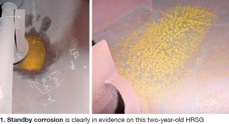
Standby corrosion
You can just hear someone on the plant staff saying to an HRSG inspector regarding unexpected waterside corrosion damage, “But we didn’t do anything to cause this condition.” Precisely the point: It was important to do something.
Thermal Chemistry Ltd’s David Addison was back at the front of the room speaking to AHUG 2012 attendees about shutdown and layup practices that would assure a flexible return to service for combined-cycle plants. He asked the first question, “What is HRSG standby corrosion?
And then answered it: Standby corrosion is the unwanted formation of non-protective iron oxides from Rankine Cycle materials—bluntly, rust. It occurs under stagnant, low-pH, and oxygen-saturated water and when high-humidity (more than 30% RH) conditions exist. The condition is often ignored. Plants in reserve, two-shifting, and frequent start/stop service are most prone to standby corrosion damage (Fig 1).
Addison said there are several risks associated with standby corrosion, including these:
- Decreases plant material thicknesses over time, creating an opportunity for failure and/or leakage.
- Causes pitting (galvanic corrosion), a condition conducive to leaks and stress corrosion cracking and corrosion fatigue failures.
- Transport of corrosion products to areas of high heat flux—such as HP evaporators—where they increase the risk of under-deposit corrosion.
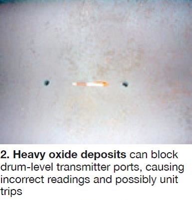
- Blockage of drum-level transmitter and sample lines with possible loss of unit control and the risk of unit trips (Fig 2).
When you place an HRSG in wet storage, Addison continued, it is critical to protect the in-service generated protective oxides—that is, hematite and magnetite. This requires maintaining the operating pH and redox conditions in storage. Specifically, maintain: (1) pH at about 9.8 by dosing prior to shutdown and during drum-level top-offs, and (2) dissolved oxygen in boiler water at 5 to 10 ppb by capping the drum with nitrogen prior to pressure collapse.
Periodic topping-off of drums likely will be required during wet storage to account for leakage and water shrinkage as the boiler cools. Important to assure that the chemistry of water added matches the boiler’s water inventory in terms of pH (by dosing with ammonia or amine) and redox potential (by controlling the level of dissolved oxygen).Also important is to circulate boiler water periodically during shutdown (every few days) to avoid a stagnant (no flow) condition conducive to pitting attack. Very few HRSGs are designed with this capability but a retrofit may be beneficial if your shutdowns can extend more than a couple of weeks.
If your station has multiple units, top off from an operating unit with matched water chemistry. If not, best practice suggests having a standby vacuum deaerator or membrane contactor to match the oxygen content of makeup to that in HRSG water.
Successful dry storage requires the removal of all moisture to achieve a relative humidity of less than 30%. This means blowing down the HRSG while metal surfaces are hot to assure residual moisture is evaporated from metal surfaces. The procedure can be challenging in the preheater and LP sections where metal temperature is relatively low.
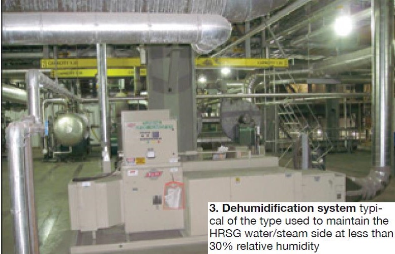
Immediately after the blowdown step has been completed, circulate dry air throughout the unit and maintain continuous flow throughout the layup period (Fig 3). Nitrogen is an alternative to dry air, but its use inhibits maintenance access. Addison suggested that the steam turbine be protected during layups in a like manner.
Storage pros, cons. The chemist then reviewed the pros and cons of both wet and dry storage to assist owner/operators in decision-making. The big benefit of wet storage, he said, is that it’s easy and effective for short outages and assures the plant’s fast return to service. However, it’s not free. Here are some of the expenses associated with wet storage:
- Installation of a nitrogen capping system and the cost of the inert gas. Note that if the nitrogen cap is lost, boiler water will quickly become oxygen-saturated.
- Installation of a pump skid to allow periodic circulation of boiler water during extended outages.
- Deaerated water is required for drum top-offs during the storage period.
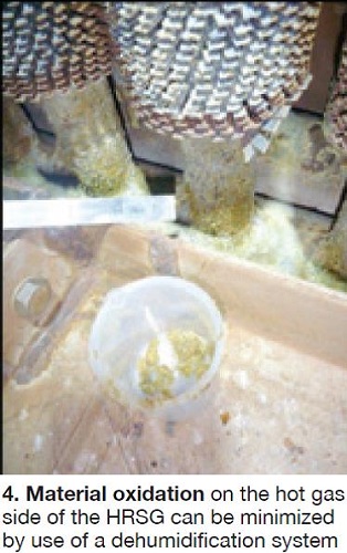
Low-humidity dry storage is highly effective for protecting against corrosion of both the HRSG (steam/water circuitry and gas side, Fig 4) and steam turbine. A big plus is that dry storage doesn’t inhibit offline maintenance and plant access. However, the cost of a dehumidification system is significant and continuous monitoring is necessary to ensure moisture levels throughout the protected areas are not conducive to corrosion. Caution: If dehumidification is done incorrectly, standby corrosion rates can be high.
What not to do when laying up an HRSG wet:
- Don’t use a reducing agent/oxygen scavenger for storage solutions, or any other treatment chemicals not normally employed during plant operation.
- Don’t partially drain the HRSG and later reapply a nitrogen cap, or refill under air.
Dry storage should not be attempted after the HRSG cools and the water is drained. It simply doesn’t work, Addison warned users. Another caution: Don’t circulate air with a relative humidity above 30%.
The chemist encouraged owner/operators to have clearly defined guidelines and procedures in place no matter what path—wet or dry—is taken. Risk assessments that involve the chemistry, operations, and engineering departments should be factored into the development of such guidelines and procedures to maximize the probability of success. Operator training is an essential part of the program.
When returning to service from storage, wet or dry, Addison recommends heavy HRSG blowdown to establish stable chemistry conditions as soon as possible. Where wet storage has been employed, remember to (1) isolate the nitrogen system, (2) set drum levels in the startup position, and (3) fire the gas turbine as soon as possible. After a dry layup, be sure to (1) line up auxiliary systems, (2) isolate the dehumidification system, (3) purge the HRSG with nitrogen to displace air, (4) fill the boiler with pH-corrected deoxygenated water to the correct drum levels for startup, and (5) fire the gas turbine as soon as possible. If solid-alkali dosing of drums is a normal procedure, include that in Step 4.
| AHUG V
December 3 – 5, 2013 Register today: http://www.ahug.co.nz/ The annual meeting of the Australasian HRSG Users Group (AHUG) provides a forum for sharing knowledge and experiences among owners, operators, manufacturers, service providers, consultants, and others with an interest in heat-recovery steam generators and associated plant processes and equipment. The group’s steering committee, chaired by Barry Dooley of Structural Integrity Associates Inc, has the following members: John Blake, Stanwell Corp. Conference program The 2013 meeting focuses on the water-treatment, mechanical, and nondestructive examination (NDE) aspects of HRSG design, construction, commissioning, operation, and maintenance. It begins with two days of presentations and discussion on the following subjects, among others:
Presentations on this year’s program, which may make this the top HRSG meeting ever in terms of content value, include:
Two four-hour workshops are scheduled for the third day, December 5:
|
Workshop
Next-generation HRSGs
The shuttering of nuclear and coal-fired generation in the name of the environment has encouraged manufacturers of gas turbines and heat-recovery steam generators to push the designs of their equipment to limits unexpected a decade ago. Today, for example, you can buy a single-shaft combined cycle for 60-Hz service with an output of nearly 500 MW (about double the rating of a late-1990s unit) and an efficiency of more than 60%. The 50-Hz version of the same system is rated 680 MW. The engineering achievement is even more remarkable given renewables-era demands that these behemoths be able to start and ramp up and down quickly.
A “high five” is due the AHUG steering committee for hosting a workshop that gave attendees a close-up view of the engineering and decision-making that underpins the development of the next generation of HRSGs. The special session was chaired by Ian Perrin of Structural Integrity Associates Inc and included presentations from representatives of Alstom, NEM, and Nooter/Eriksen.
Overview. Perrin outlined some of the challenges facing designers of advanced HRSGs, and by extension, engineers responsible for high-energy piping and bypass systems, to focus the attention of participants on the workshop’s agenda. The challenges, he said, include the following:
- Larger HRSGs to accommodate the higher exhaust-gas mass flows from G-, H-, and J-class gas turbines.
- Higher GT exhaust-gas temperatures and velocities.
- Larger-diameter and thicker-wall pressure parts.
- Increased use of creep-strength-enhanced ferritic steels and advanced stainless steels.
- The higher operating pressures, temperatures, and flows characteristic of advanced HRSGs have a significant impact on boiler and piping design. Perrin offered the following comparison as evidence:
- Case 1: Relatively conventional HRSG by today’s standards, designed to produce 800,000 lb/hr of 2200 psig/1050F HP steam; Grade 92 components.
- Case 2: HRSG for a more advanced turbine, designed to produce 950,000 lb/hr of 2600 psig/1100F HP steam; Grade 92 components.
For the same flow velocity (pressure drop), pipe diameter increases from 12 to 16 in. in going from Case 1 to Case 2 conditions. In addition, pipe wall thickness doubles from 1 to 2 in. and pipe weight increases by 2.4 times.
Changing the material in Case 2 to Super 304H austenitic stainless steel, which is designed for high-temperature service (creep-strength-enhanced ferritic steels generally are restricted to applications where steam temperatures are below 1175F), pipe diameter can be held to 14 in. and the weight increase to only 1.3 times that for Case 1. Pipe wall thickness remains about the same as Case 1.
Perrin pointed to the increased use of advanced ferritic and stainless steels today to limit the wall thickness of pressure parts. However, he cautioned that material selection requires careful consideration. Example: Super 304H, while attractive because of its high-temperature strength, has a larger coefficient of thermal expansion and a lower thermal diffusivity than some alternatives. Also, the use of stainless steel introduces the need for dissimilar metal welds (DMWs).
With higher exhaust and steam temperatures, he continued, consideration must be given to oxidation resistance of pressure parts and structural supports (such as tube restraints), etc. For temperatures above 1175F, perhaps coatings will enable use of ferritic steels. Austenitic stainless steels have better oxidation resistance, to about 1400F, but they are prone to exfoliation. Shot peening might help there.
The high exhaust-gas mass flows associated with large gas turbines impact superheater and reheater designs as well as the design of the inlet duct. Gas velocity is of concern because of its possible effects on tube vibration and heat absorption.
Codes and standards require scrutiny, Perrin advised. New designs will operate at conditions that may be outside of previous experience. Section I of the ASME Boiler and Pressure Vessel Code still does not consider cycling, but the EN Code does. However, it is lacking in other areas. And neither code addresses creep-fatigue interaction.
Alstom was first to present among the boiler OEMs. The speaker divided trends influencing design into two groups: operational and steam/water cycle (Fig 5). The latter essentially duplicated what Perrin had said earlier. Operational trends/challenges included an increased number of on/off cycles, high ramp rates, and low-load operation. A concern expressed was that on cold starts, HP and reheat manifolds are subjected to high-temperature gradients. Tubes heat up quickly before steam flow from the drum is established; manifolds are cooler.
Next Generation GT exhaust temperatures are within the current experience range, the speaker said. He added that steam temperatures may increase above current levels to boost cycle efficiency; also that peak steam temperatures may occur at part load or during duct firing.As steam-flow requirements increase, the speaker said, the options are to increase HRSG width or height. If width is increased, more tubes are added to maintain velocity and pressure drop; if tube length is increased, velocity and pressure drop increase as well. Steam-drum length is extended as output increases to maintain the same shell diameter and wall thickness.
Alstom attributes some of its HRSG’s operational flexibility to the use of multiple desuperheaters—one between the final two stages of superheating and one between the HP outlet and the steam turbine. Also to an integrated plant design that allows owners to manage fast-start GT exhaust conditions to meet steam-turbine ramp-rate limits.
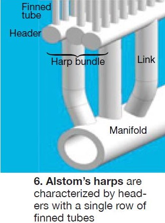
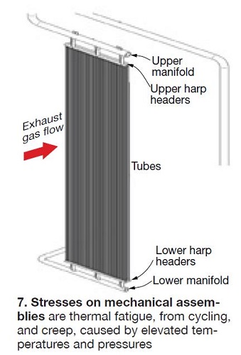
Each OEM’s boiler has one or more design features to satisfy market demands. Alstom’s HRSG is characterized by what it calls the OCC™ (Optimized for Cycling and Constructability) design. Its finned tubes have no bends and harps have only a single row of tubes as shown in Figs 6 and 7. Shop content is maximized to minimize field labor. An enhanced drum-nozzle configuration contributes to lower stress concentrations where nozzles connect to the drum.
Fast-start capabilities of the OCC design are the following: 30 min for a hot start (maximum shutdown of about eight hours); 100 min for a warm start (maximum shutdown of about 60 hours); 150 min for a cold start (shutdown of more than 120 hours). The speaker said the HP and reheater manifolds are the limiting components in terms of fatigue life, not the steam drum. The OEM’s calculations show that fast hot starts will consume the most component life because of the high number of starts. For example, a cycling HRSG might expect to have 4000 hot starts over its lifetime, 1000 warm starts, and 200 cold starts.
NEM’s presentation covered much the same material as the other OEMs with two significant exceptions: mention of VM12, a new material for pressure parts in demanding service, and DrumPlus™, the company’s solution for fast start/fast ramp at high steam pressures and temperatures.
VM12 (for Vallourec and Mannesmann), a 12%-chromium steel containing cobalt, tungsten, and boron, was developed for advanced HRSGs and other applications. It is said to combine good creep resistance and high steam-side oxidation resistance. V&M says it has successfully demonstrated production of the material in several laboratory and industrial heats, and several sizes of tubes and pipes have been fabricated using different rolling processes. Extensive testing suggests the material is ready for prime time and the NEM speaker seemed positive about VM12’s promise for the EN market in the near term. However, there’s no commercial experience to date and ASME has not yet blessed the material.
NEM’s way for accommodating fast starts and ramps at today’s challenging steam pressures and temperatures is DrumPlus, which combines the advantages of drum-type and once-through HRSGs. Design is largely in accordance with a conventional drum-type HRSG but with the advantages of a once-through unit.
In brief, the conventional HP drum, which would be susceptible to fatigue damage in a fast-start application, is replaced by a knock-out vessel and external separator bottles. This smaller drum has a relatively thin wall to accommodate thermal stresses. Because of the reduced volumes of both steel and water, DrumPlus has the dynamic capabilities of a once-through unit; however, it has considerably more water inventory to provide a higher degree of operational flexibility. Also, DrumPlus does not require the condensate polishing system recommended for a once-through boiler.
The Nooter/Eriksen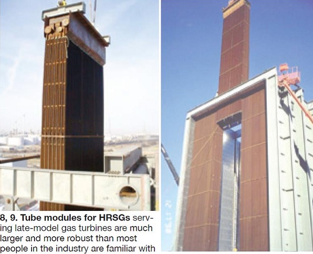 presentation began with a review of the following impacts gas-turbine size has on the design of a conventional triple-pressure HRSG with reheat:
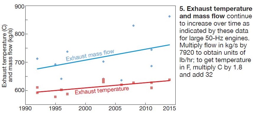
- HP and reheat design temperatures are going higher and higher. An HRSG on the back of a late-model, 60-Hz, F-Class gas turbine might be designed for an HP steam temperature of 1115F, for a G-Class turbine that might go to 1150F, and for a J-Class unit, 1215F. Recall that back in the 1990s, HP steam conditions for an F-Class turbine were in the neighborhood of 1820 psig/1055F; in the mid 2000s, 2425 psig/1085F.
- HP steam piping diameter and wall thickness.
- Structural members.
- Basic module/casing configuration.
- Stack diameter/height.
The speaker showed photos of several plants with today’s largest HRSGs and presented thumbnail sketches of the Nooter/Eriksen projects. Figs 8 and 9 offer eye-popping perspective.
Next, the following design features conducive to cycling were suggested:
- Tube stubs for HP and reheat panels.
- Reliable drains system.
- Reheater steam bypass.
- Stack damper.
- External stack insulation.
- Economizers with return bends between tube rows, no tube bends at the inlet header, no pass partition plates, and tube-to-tube expansion flexibility.
- Desuperheaters of the nozzle ring design equipped with separate control valves, piping liners, and drain pots downstream. The latest control logic should be employed for operating block and control valves.
- Instrumentation to enable duct-burner heat release across the entire unit.
- Advanced monitoring and control techniques for water chemistry, drum level, and duct burners.
- HP and reheat sections designed to accommodate expansion, such as by use of flexible coil arrangements.
- Spring hanger header support.
- Use of higher strength steel for steam drums—such as SA-302 Gr B—can have a dramatic impact on the life of a drum in cycling service. The speaker provided the following comparison between a standard SA-516 Gr 70 shell material and SA-302 Gr B for a drum designed for 2625 psig/685F with a 64 in. ID. Shell thickness for the 302 material is a nominal 4 in., about an inch thinner than for the 516 steel.
For a 30-yr projected life, the assumption is that the HRSG will make 300 cold starts (from 60F), 1800 warm starts (from 212F), and 6000 hot starts (from 500F). For the 302 material, the 300 cold starts would consume 17% of the drum’s fatigue life and the 1800 warm starts, 15%. By contrast, 300 cold starts with 516 steel uses 63% of the drum’s fatigue life; the 1800 warm starts, a whopping 115%. The hot starts have virtually no impact on fatigue life with either material. The bottom line: The 302 drum consumes less than one-third of its fatigue life in 30 years while the 516 drum is at end of life in less than 17 of its expected 30-yr life. CCJ