
Clean fouled HRSG tubes, increase revenue
By Christopher Norton and Randy Martin, Environmental Alternatives Inc
Gas-side deposits and corrosion of HRSG heat-transfer surfaces are inevitable and are a common cause of reduced steam production, low steam temperatures, and degraded gas-turbine performance. These effects contribute to reduced electricity production and lost revenue.
Many factors contribute to deposit formation on HRSG tubes—including fuel sulfur content, tube leaks, insulation failures, ammonia injection in excess of that required for NOx control, and condensation caused by low stack temperature. Corrosion also is problematic at plants operating in locations with high humidity, particularly those facilities designed for base-load service and required to cycle. Additionally, HRSGs equipped with oil supplemental firing experience an increased rate of tube fouling than when burning only natural gas.
Over time, fouling can bridge the gap between adjacent tube fins or other heat-transfer surfaces, further disrupting heat transfer and increasing gas-side pressure drop. Recall that gas-turbine (GT) and combined-cycle efficiency decrease with increasing delta p. In cases where HRSG performance is severely compromised, the entire plant may require an extended forced outage to repair corrosion-induced tube leaks, remove deposits from heat-transfer surfaces, or even replace an entire module.
Mitigate deposits, corrosion
 Removing HRSG gas-side deposits should be a part of every plant’s annual maintenance program. Effective planning can be improved by closely monitoring specific operating parameters—such as GT backpressure, steam production and temperature (for each pressure level), and stack temperature—and comparing the data against corrected plant design conditions. Plant heat rate and output also should be tracked.
Careful review of the data can provide advance warning about the location and amount of fouling, and the rate of deposit formation within the HRSG. This information allows the owner to determine precisely when an outage for tube cleaning is economically justified. In general, HRSG cleaning is required when the gas-path pressure drop across the HRSG reaches 3 to 4 in. H2O over the “new and clean” condition.
Once the need for cleaning has been established and an outage date determined, the next step is to select the optimal cleaning technology. The standard options are high-pressure water blasting, grit blasting, acoustic cleaning, and CO2 blast cleaning. The plant owner should carefully consider the pros and cons associated with each cleaning option before making a final selection.

High-pressure water can be effective but may also have the undesirable side effect of a water/deposit interaction that creates an acidic environment and accelerates tube corrosion. It also could turn the water/deposit mixture into a concrete-like substance when the plant is restarted. Important to remember is that this cleaning technique is limited to line-of-sight deposits and the high-pressure water may push removed deposits further back into inaccessible regions of the HRSG.
Unless carefully performed, high-pressure water blasting also can quickly damage insulation that is extremely difficult to access for repairs and/or may erode some tubes or damage tube fins. Finally, contaminated water is difficult to contain and may require expensive waste disposal, if determined to be a hazardous waste.
Grit blasting, also limited to line-of-sight cleaning, can quickly thin the tube wall or damage fins if not carefully performed by experienced technicians. Unfortunately for the plant owner, thinning of tube walls is not obvious during cleaning but will become apparent when the rate of tube leaks increases in the future. Like high-pressure water blasting, A large amount of waste material is generated, some of which may be classified as hazardous and require special (read “expensive”) handling and disposal.
Owner/operators report mixed results when using sonic horns for deposit removal, particularly in the cold end of the HRSG. Sonic blasting is ineffective for removing ammonia salts and baked-on deposits.
CO2 blast cleaning
The remaining option for HRSG cleaning is CO2 pellet blasting, the only option that is non-secondary waste products. This is a dry process and does not contribute to corrosion or erosion of heat-transfer surfaces. Just as important to the owner, deep cleaning between tubes can be performed.
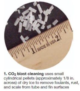
 CO2 blasting penetrates and completely cleans modules located deep within the HRSG, eliminating the time and expense of mechanically spreading tubes to access tubes not in the technician’s line-of-sight. It has been proven by over 20 years of industry experience and is recognized by HRSG manufacturers as a cleaning best practice (Fig 1).
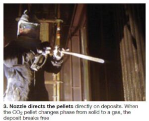
The general cleaning process is illustrated in Fig 2. CO2pellets are fed into a portable machine that is connected to a high-pressure compressor. The pellets are educted into the air stream and propelled through a hose to a specially designed nozzle that propels them at speeds up to 1000 ft/sec. The pellets exit the nozzle and penetrate the debris layer on the surface being cleaned (Fig 3).
The CO2 sublimates once the pellets penetrate the deposit. During sublimation at atmospheric conditions, the CO2 pellets undergo a transformation from a solid directly to a gas, unlike ice that must first melt into liquid water before evaporating into vapor form. When CO2 sublimates from a solid to a vapor, it expands 750 times in volume creating a “mushroom” effect inside the deposit that lifts and removes deposits from metal surfaces. A HEPA vacuum system collects the debris. Two typical HRSG tube banks shown prior to and following CO2 blast cleaning in Figs 4 and 5, respectively, illustrate cleaning effectiveness.

Making CO2 pellets
High-density CO2 pellet production is the cornerstone of the cleaning process. Sufficient pellets are manufactured onsite to guarantee the quality and density for maximum cleaning effectiveness. Pre-made pellets from an offsite dry-ice vendor usually are 24 to 48 hours old before they are used and will have already experienced a loss in density. Lower-density pellets begin to sublimate in the hose and “soften.” Soft pellets are a less-effective cleaning medium because they are less able to reach the bundle interior.

Onsite production of high-density CO2 pellets is possible by using a completely self-contained mobile support trailer (Fig 6). The trailer houses a 350-psig air compressor, air dryer/after-cooler (for clean instrument grade air with low moisture content), a liquid CO2 storage tank, a pellet conversion unit, and all necessary support systems for direct connection to onsite power. The trailer also carries all the necessary tools, personal protection equipment, and other safety gear to the plant.
Case studies
The true effectiveness of high-density CO2 pellet blast cleaning becomes evident when comparing pre- and post-cleaning plant performance data—such as pinch points, steam flow, heat rate, fuel consumption, pressure drop, and unit power. In the first case study, the performance restoration experienced after cleaning is presented. In the second, the value of a CO2 blast cleaning allowed the owner to cancel a scheduled major outage and avoid purchasing a replacement economizer module.
Regaining lost performance
Monitoring important performance data points at a nominal 500-MW combined cycle in the Northeast is part of the plant’s ongoing HRSG maintenance and cleaning program. The data collected are used to develop performance trends and to estimate the power output that can be restored by cleaning. A simple economic analysis compares the value of lost power sales revenue when running with a fouled HRSG, with the lost revenue incurred for an outage and the cost of an HRSG cleaning. This analysis helps the plant owner decide when a cleaning should be scheduled.
Data collected from the plant historian before and after an HRSG cleaning is shown in the table. The capacity restored as a direct result of the cleaning was 1120 kW. This plant normally operates at a 90% capacity factor and sells power into the market at 3.5¢/kWh off-peak, a conservative price. Assuming the plant can sell the additional power generated, the gross savings resulting from the restored power is about $309,000 annually. The owner’s payback for the HRSG cleaning is a matter of weeks.

Another approach to determining the value of an HRSG cleaning is to calculate the fuel saving that occurs when a plant runs at a fixed power output. In that situation, the fuel savings is a function of the plant’s improved heat rate. If the HRSG gas-side pressure drop increases by 4 in. H2O because of fouling, the resulting heat-rate increase can be determined from plant-specific design data.
For this case, the heat-rate improvement is approximated as proportional to the power restored (1120 ÷ 500,000) or 0.22%. Assuming a typical 500-MW combined cycle has a gross heat rate of about 7000 Btu/kWh, the heat-rate restoration is about 16 Btu/kWh. If fuel is purchased at $3.50/million Btu then the annual fuel savings for the improved heat rate is about $220,000.
Avoiding an unexpected cost

The second case study involves a combined-cycle cogeneration plant in the UK that produces steam and electricity for two paperboard mills. The plant is equipped with a GE LM6000 gas turbine and a Siemens steamer.
Sticky combustion products were condensing out on the HRSG economizer tubes as a tar-like substance because the flue-gas temperature had dipped below the dew point. In addition, ceramic fiber insulation blocks used in the HRSG combustion zone were deteriorating with fiber strands coming lose into the gas flow and sticking on the economizer’s finned tubes. The combined effect was a loss of heat transfer in the economizer and a rise in the HRSG gas-side pressure drop that significantly reduced steam production.
 Initially the plant owner thought to replace the entire economizer module with one having a recirculation system to take a portion of the hotter economizer outlet water and return it to the inlet to ensure tube-metal temperature remains above the dew point. However, procuring an expensive new economizer module was going to require at least 40 days, thereby putting the plant owner at commercial risk for failing to supply the contracted amount of steam.
Alternative approach: The plant owner investigated cryogenic cleaning of the economizer even though there was no large boiler experience with the technology in the UK at the time. However, dry ice was used to clean small equipment—such as motors and generator windings. The plant owner sent representatives to the US to observe the cleaning process in action and the decision was made to bring the process to the UK for the first time.
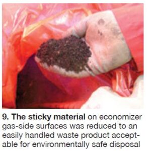
The CO2 pellet blasting equipment was shipped to the UK for a planned HRSG outage. Figs 7 and 8 show the state of economizer tube fouling before and after cleaning; Fig 9 shows the debris removed from the HRSG after the cleaning was completed.
The cleaning process was very successful and at the close of the outage the plant resumed supply of the contracted amounts of steam to the customer. By selecting CO2 pellet cleaning, the owner avoided an unnecessary economizer replacement, sidestepped an extended outage for the economizer replacement, and avoided an unpleasant contract discussion. CCJ
