Mechanical Dynamics & Analysis (MD&A) recently completed the major inspection and refurbishment of a 1 × 1 combined cycle at the Hermiston Generating Plant that successfully returned the facility’s turbines and generators to full and reliable operation.
The project began with the full major inspection of a late-1990s-vintage, 170-MW 7FA gas turbine—including the robotic inspection of its 7FH2 generator. The A10 steam turbine and its 7A6 generator also were fully inspected and refurbished by MD&A in the same outage.
The plant
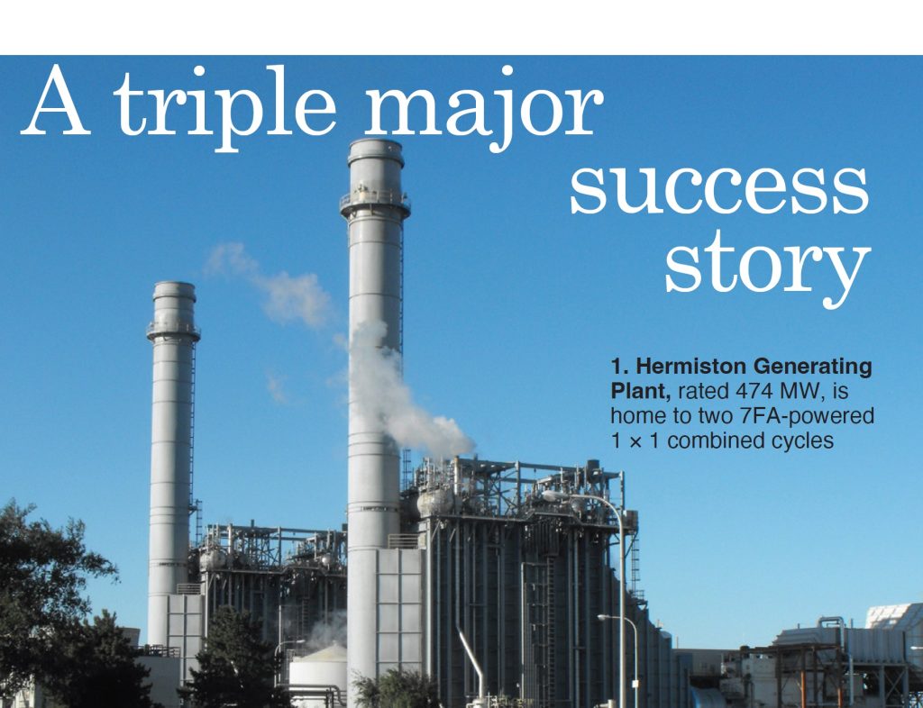
Perennial Power’s 474-MW, two-unit Hermiston Generating Plant in northeastern Oregon (Fig 1) provides power to nearly 500,000 households in the Pacific Northwest. It also sends steam to Lamb-Weston’s adjacent potato processing facility.
Both Hermiston units feature identical gas turbine/generators and steam turbine/generators, all commissioned in 1996. The plant has been recognized by the Oregon Occupational Safety and Health Division in the past for its exceptional health and safety record and to date has never experienced a lost-time injury.
The outage
Safety, planning, communication, and coordination were instrumental in the successful Unit 2 outage in fall 2022.
Plant Manager Chad Daniel takes us back to the outage and offers an insightful and educational look at what made it run smoothly.
“I can’t over-stress the importance of pre-outage planning and open communication among the plant, the various technical points of contact, and all contractors,” he explains. “We had 20 contractors on site, MD&A being the largest, plus additional subcontractors.”
Daniel explains that pre-job planning and walkdowns are absolutely critical.
“There are things that come up during walkdowns (crane activities, for example) that may need to be altered, sequences shifted, and you are always looking for safety items. All of these are critical to a successful outage.”
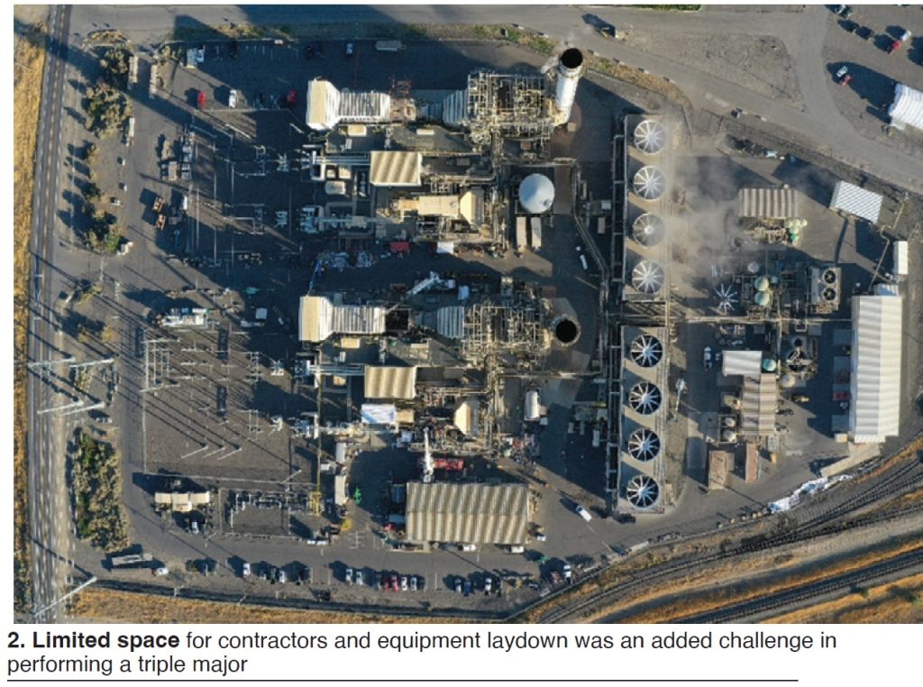
He continues: “With nearly two-dozen contractors onsite and within limited space (Fig 2), communicating and coordinating contractor milestone schedules and needs become crucial (competing for space, LOTO timing, equipment testing, safety concerns, etc).
“Our plant has found that by having multiple internal pre-outage meetings combined with specific responsibilities and work-order and contractor assignments, you make sure that no single person is overloaded. At Hermiston everyone shares those responsibilities, both salaried and non-salaried. Our internal meetings and reporting start several months before the outage. Meetings with contractors are also held onsite or virtually as often as needed.”
“It starts with the plant,” states Daniel. “I feel it is the site’s responsibility to build the dialogue, the trust, and the open communication to bring up any and all questions and make it a streamlined and safety-conscious outage.
“The result,” as he explains, “is that once you get rolling into the outage, you have the relationships, you know who you need to talk to, you have people that you are comfortable with
and have faith in so you can walk through the issues, get them resolved quickly, and keep everyone involved and moving ahead.”
Daniel also addressed weather-related scheduling, offering an important caution for outage planning. Although his part of Oregon does not routinely experience extreme weather, the climate can still be unpredictable, especially in the fall and spring. So, you need to consider temperature swings, and high winds than can impact crane operations.
“When you are planning your outage, whether it’s based on the owner’s needs or the hours on your machine, certainly leave a few extra days for contingency, if possible, particularly for a major inspection where you are going to be down for a substantial amount of time, are performing non-routine work, or work that poses increased risk of delays. You have to be mindful of the end timing of the outage and keep weather conditions in mind for startup. You don’t want to be starting the HRSG, for example, in freezing conditions,” he notes.
7FA gas turbine
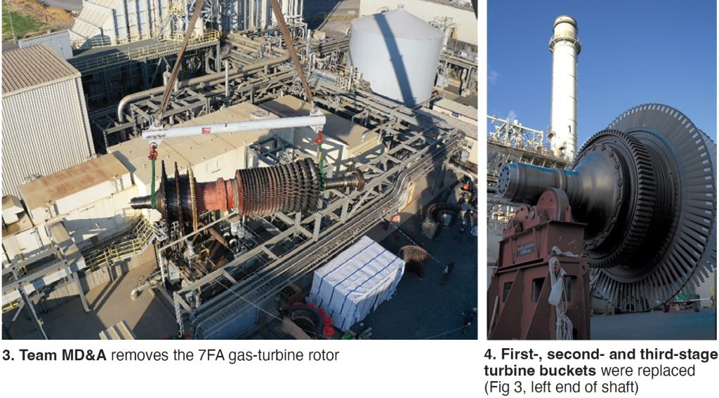
MD&A mobilized and completed the disassembly process utilizing a two-shift operation (Fig 3). Detailed visual inspections began, coupled with detailed NDE, followed by the recommended refurbishments.
In the turbine section, first-, second- and third-stage buckets were replaced (Fig 4) due to rubbing wear and loss of the thermal barrier coating (TBC).
First-, second- and third-stage nozzles also were replaced because of foreign object damage, evidence of cracking, and coating loss. Inspections and similar indications revealed the need to also replace the shrouds.
In the combustion section, liners and transition pieces were replaced with refurbished sets due to TBC loss. New inner crossfire tubes and retainers were installed because of wear and outer crossfire tube packing was replaced at reinstallation.
Although no abnormal visible wear was found, forward combustion cans and fuel nozzles were replaced with customer-provided refurbished sets. Flow sleeves also showed no wear, but the flow-sleeve piston rings were replaced.
Liner caps were replaced with refurbished ones, and transition-piece bullhorn brackets were found worn and replaced with new.
For the compressor-section inlet guide vanes (IGVs), MD&A replaced gears, rack, inner and outer bushings, and spacers. IGV blades themselves will need to be replaced at the next major inspection.
Rotating and stationary blades showed no damage. R-0 inlet compressor blades were replaced with a refurbished set and shims were added to stages 14, 15, and 16. The casing and rotor showed no need for immediate action, but the discharge casing retention bars were replaced.
The inactive thrust bearing showed heavy scoring and the T-1 and T-2 bearings revealed pitting and scoring, which were subsequently replaced with refurbished bearings. The active thrust bearing was cleared for service.
7FH2 generator
For the generator, the initial scope of work was visual inspection, robotic wedge-map analysis, electromagnetic core imperfection detection (ELCID), and a full battery of electrical tests.
The borescope inspection showed substantial widespread greasing and several areas that had loose hardware. Field removal was recommended for a more comprehensive stator investigation. Following that, a core wedge map was performed that showed approximately 90% of the wedge system was loose and/or hollow, not meeting MD&A criteria. A full stator re-wedge, replacement of greasing blocking/ties, and axial support tightening was recommended and performed.
MD&A also provided and installed an improved wedge design.
Prior to re-wedging, a significant amount of time was expended cleaning the core. All slots were cleaned, including dovetails.
New filler material and top ripple springs were installed during the re-wedge. A modification was made to the end wedges to improve mechanical strength. The original flux probe was installed without issue, and a final ELCID was performed with acceptable values.
Based on modal bump testing, MD&A recommended that the entire collector and turbine ends have series blocking installed to reduce resonant frequency response. Saturated felt and ties were added to dampen the response.
New axial support hardware was installed, replacing the loose axial supports and hardware found during initial inspections. Locking epoxy was applied on all hardware to ensure no complications during operation.
Hydrogen seals were replaced with new, and field collector rings were ground.
Successful electrical testing was performed at the completion of all work performed.
A-10 steam turbine
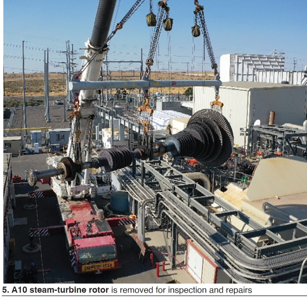
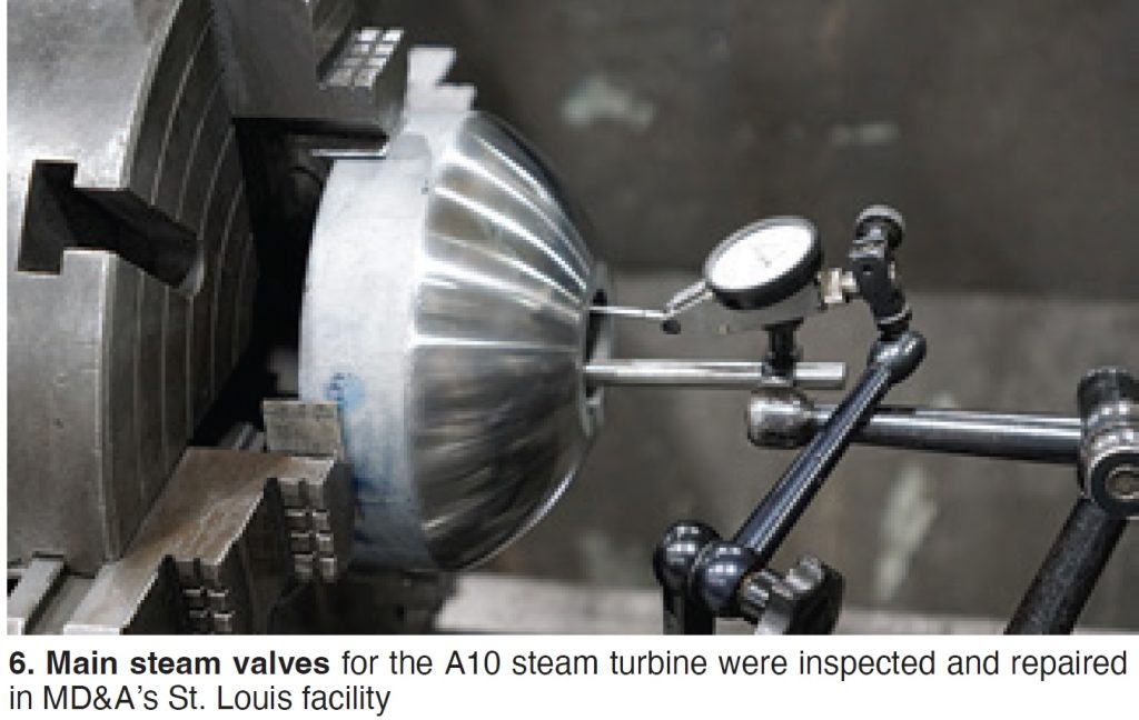
MD&A performed a major inspection and overhaul of the 81-MW A10 steam turbine (Fig 5) and its generator stator and field—all installed in 1996. The main steam valves also were removed by MD&A and sent to the company’s St. Louis facility for inspection and repairs (Fig 6).
MD&A specialists performed a complete steam-path structural audit of the A10 machine. Although many minor diaphragm indications could have been repaired by MD&A onsite, ILP diaphragms 9, 10, 11, and 13 were shipped to MD&A’s facility for major repairs. Stages 10 and 11 also had inserts installed on the steam-seal face because of dishing.
HP and ILP rotors remained coupled and were removed for sandblasting and NDE. Minor bucket repairs were performed onsite to correct impact damage and moderate solid particle erosion.
On reassembly, MD&A performed a Topless Laser Alignment® and its On-Site Seal Services fit and installed new diaphragm and gland-steam packing.
7A6 Generator
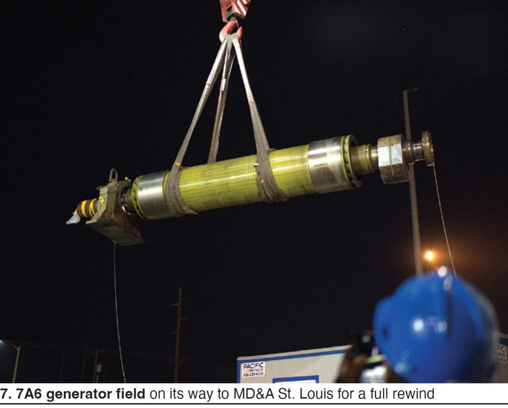
The 7A6 air-cooled generator was disassembled and its field removed and shipped to MD&A’s St. Louis facility for a full rewind (Fig 7). In addition, the company’s Generator Div mobilized onsite to perform a full stator rewind.
The combined HP stop and control valve was disassembled and the cores shipped to St. Louis for inspection and repair. The Steam Turbine Repairs Div also received two reheat stop valves and two intercept-valve cores for inspection and repair.
Stator. Concurrent with the steam-turbine major inspection, an elevated workspace was constructed onsite to support the generator division in stator disassembly and reassembly work. A baseline ELCID was performed to determine integrity of the current stator core iron. No shorted laminations were noted.
The wedge system was removed, then the flex probe was carefully set aside for reassembly.
With wedges and series loop connections removed, bar removal began. Inner axial supports were left in place and prepared for the reassembly. Connection pieces were cleaned for reuse.
The stator was thoroughly cleaned to remove any contaminants from the wedge/bar removal process. A post wedge/bar removal ELCID indicated no core-iron damage during wedge and bar removal.
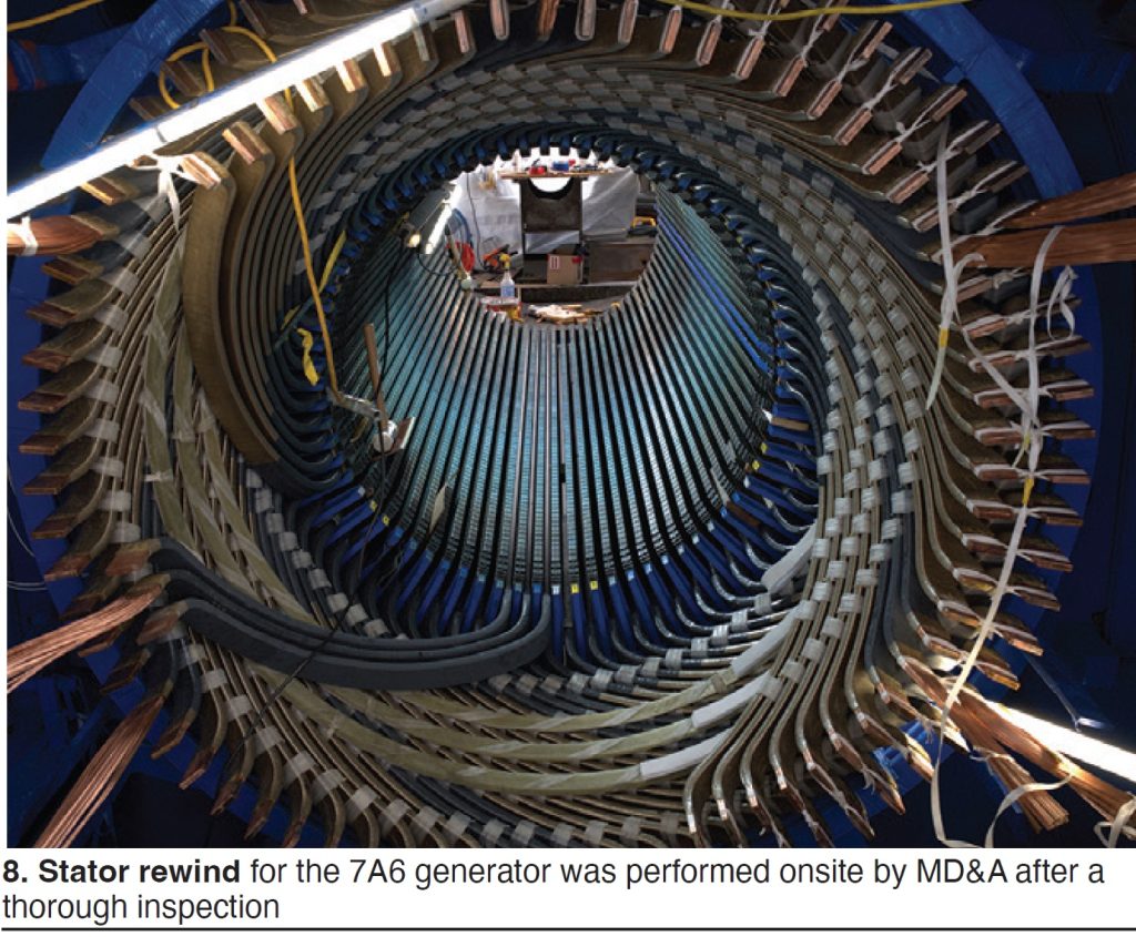
Each core slot was cleaned, and a detailed inspection of any abnormalities was conducted. The core compression flange and all exposed areas where the endwindings sit were painted with an epoxy paint for a uniform color on the compression flange.
After thorough cleaning, the rewind began (Fig 8).
Bar boxes were moved to the scaffolding deck with an innovative safety-conscious method of disassembling the scaffolding roof and flying the boxes to the deck with a crane following completion of a detailed lift plan.
Each of the six circuit rings were acceptance-tested, and the outside binding bands installed.
A tapered gauge from the bar manufacturer was used to ensure concentricity was achieved on the four binding bands. Concentricity of each band is a vital step that will properly align each bar and subsequentially the endwinding basket once the rewind is completed.
Two top and two bottom bars were installed to ensure alignment. Bars were fit into a shoe on the collector end and carefully transferred through the bore to the turbine end. All 72 bottom bars were installed, blocked and tied. All 72 top bars were then installed, blocked and tied, along with 12 new resistance temperature detectors (RTDs).
After all bottom bars were installed, a Hipot test was performed to ensure there was no bar armor insulation damage. Another Hipot was performed on all top and bottom bars at the completion of top-bar installation.
Wedges were then installed, and filler was adjusted at each wedge for proper radial compressive force. Axial locking pins were installed, followed by a final ELCID and brazing. The existing circuit-ring copper connection pieces were re-used and brazed to respective top- and bottom-phase connections.
Upon completion of all rewind activities, final electrical testing consisted of winding copper resistance, insulation resistance, and a final Hipot of each respective phase. Each phase produced satisfactory resistance values.
The stator rewind activities progressed as expected throughout this project. The consistent bar shapes and robust bar design aided in completing the project without incident.
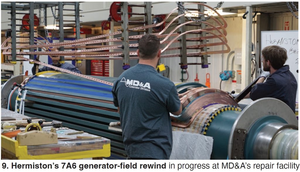
Field. The 7A6 generator field was sent to MD&A in St. Louis for testing, disassembly, coil removal and cleaning, further testing, reassembly, and high-speed balance (Fig 9).
During initial electrical testing of the heavily dished collector rings, collector studs, and bore copper, the collector studs failed high-potential testing. This resulted in the replacement of the collector rings which included removing the old collector rings, manufacture of new collector rings, new collector-ring insulation, and reinsulating of the collector studs.
Coils were removed and sent offsite for cleaning. They were then returned and checked by MD&A. After reinstallation, each coil received ac Hipot and turn-to-turn testing.
Also, during the rewind process, the blocking was upgraded to the MD&A standard block and tie design. Turn insulation was coated, requiring a rotor bake cycle.
Electrical testing, high-speed balance, acceptance testing, and shipping followed.
MD&A also provided startup and balance support of the unit, along with full recommendations on what to look for or replace at the next outage. Daniel offered the following: “MD&A has become one of our most trusted, dependable and transparent contractors to work with.”
Balance of plant
Throughout the outage, balance-of-plant work was conducted using both Hermiston plant personnel and a wide variety of contractors.
Major items beyond the base MD&A scope included the following:
- Vogt 3-drum HRSG-related items:
-
- Boiler feedwater pump replaced.
- Insulation repaired and replaced on numerous HRSG piping systems.
- NDE inspections on HRSG and feedwater piping.
- SCR dilution-air fan motor replaced.
- Stack-damper linkage repairs.
- HRSG blowdown-tank modification; check valve added to quench-water line.
- Rebuilding of HP and reheat attemperator, IP feedwater, HP feedwater and other valves.
- Completion of state-required internal boiler inspections.
-
- Other items included these:
-
- More than 200 corrective, demand-task, and PM work orders completed by plant personnel.
- Instrument transmitters and switches calibrated for numerous plant systems.
- Diesel fire pump rebuilt.
- Cooling tower: tower basin silt removal and cleaning, routine inspections, fill-material sample cell weights obtained, minor structural repairs, replaced all circ-water-system 6-in. lateral piping grommets in all four tower cells, circ-water pipe header expansion joints replaced.
- MCCs, SF6 breakers, 52G, and 4160-V contactors tested/inspected/cleaned.
- CO2 and deluge fire systems inspected/tested.
- Lube-oil plate-and-frame heater exchangers for the steam and gas turbines disassembled, plates cleaned, gaskets replaced, and reassembled.
- Steam-turbine pedestal restoration; epoxy repairs.
- Gas- and steam-turbine Mark-V control system health-check inspections completed.
-
Outage results
Overall performance of the gas turbine improved as a result of the outage. Corrected output increased by 4701 kW (3.1%) and corrected heat rate decreased by 185 Btu/kWh (-1.9%).
Forecasting
A forecasting note extracted from discussions with plant personnel: “One critical item that helps us prevent negative surprises at Hermiston actually starts years before the outage.” Daniel explains: “We review post-outage equipment and engineering reports as soon as possible after the outage, while the information is fresh. There are always recommendations for future outages in these reports.
“Also, there can be non-critical jobs that can’t be completed during the outage, and they can get overlooked as we go back to post-outage duties. So, we try to issue work orders for these items right away so they can be tracked and remain visible.
“We’ve found that by practicing this, our maintenance budget forecasts are more accurate, and we have fewer surprises during future outages.”
Final notes
Hermiston has received several awards over the years from CCJ for both safe operations and best practices. Examples include self-performing combustion inspections, hydrogen-purge remote activation, and others searchable at https://www.ccj-online.com/
Editors’ discussions with Daniel on this outage noted the overall safety theme. “Best-practice safety adjustments” and “safety communication among all personnel” were repeated and emphasized, as was an attitude of trust and respect for all organizations and personnel involved.
“Every individual onsite, whether a plant employee or contractor, regardless of pay grade or title, has Stop Work authority,” he states.