


CONTENTS
 Hot topics @ upcoming meeting
2013 conference highlights
Clashing panel
Rotor-life panel
Performance enhancement
Avoid trips on liquid fuel
Air filters
Controls panel
That’s all it costs to register for the 2014 7EA Users Group meeting, October 21-23, in the Nashville area—if you do so before August 12. Miss that deadline and the fee is but $150, until September 24; after that it’s still only $250—meals included. This could be the biggest bargain in the industry given the technical information, best practices, lessons learned, etc, that you can take away from the conference and implement at your plant to improve performance and safety and reduce costs. Even throwing in an airline ticket and hotel bill, the average user will spend less than $1000 of the company’s money. It’s hard to believe that the most parsimonious of owners wouldn’t go for this deal.
Pat Myers, plant manager of AEP’s Ceredo Generating Station, and his colleagues on the steering committee (sidebar) are a no-frills group that focuses on content. The committee had not finalized the program, Myers told the editors by phone in early July, but some of the high-profile presentation/discussion topics planned included the following:
- The finding of cracked Row 1 stator blades in the area of concern identified in Technical Information Letter 1884, “7EA R1/S1 Inspection Recommendations,” issued Apr 26, 2013. This document is often referred to by users as the “clashing TIL.”
- Reactivation of liquid fuel on machines because of the gas curtailments experienced the past winter.
- Oil mist separator/general lube oil leakage on 7A6 generators.
All this, and much more, for only 50 bucks: Register today. Follow program updates at http://ge7ea.users-groups.com/.
TIL 1884 area of concern findings are sure to kick the program into high gear right out of the box because the liberation of an airfoil at this location could destroy the compressor. Thought leaders from Advanced Turbine Support LLC, President Rod Shidler and Field Service Manager Mike Hoogsteden, will open the meeting once again with their State-of-the-Engine presentation. It was an inspector from Advanced Turbine Support who in mid-May found the first area of concern cracks reported publicly.

By way of background, recall that clashing is the term used to describe the contact between rotating blades and stationary vanes that has occurred in some compressors for GE frame engines. Recent inspections confirm the following:
- Clashing damage in terms of severity, and number and location of affected airfoils, is increasing in at least some compressors.
- Damage from clashing, which had been characterized solely by wear and tear on the trailing edges of rotor blades near their platforms (Fig 1) and on the leading edges of adjacent stator vanes at their tips (Fig 2), now also may include cracks in vanes a few inches from the bottom of the airfoil in the middle of the convex side (Fig 3)—the so-called area of concern.
When clashing was first reported by an owner/operator at a 7EA User Group meeting several years ago, the damage was found in vanes located at or near bottom dead center (6 o’clock position) of the first-stage ring segment. Since then, S1 damage has been identified in more than 90 7EA compressors by Advanced Turbine Support inspectors alone and at locations other than near bottom dead center. Examples of findings in the top right quadrant of the casing: Vanes 13-15 in a unit with nearly 10,800 hours of service and 2000 starts; nine vanes between 1 and 14 in a machine with nearly 40,000 hours and 2000 starts. Numbering convention is from the split line at the right (looking downstream) counterclockwise (Fig 4).
Advanced Turbine Support inspections also have confirmed clashing of second-stage airfoils on about two dozen machines.
One user told the editors the OEM’s engineers attribute clashing to increased tip deflection caused by a rotating-stall-driven S1 vane frequency response during startups and shutdowns (Figs 5, 6). The frequency response, together with a loss of damping attributed to ring-segment “lock-up” caused by corrosion, produces higher-than-normal operating stresses. But not everyone is convinced this is the only cause.
Steering Committee
Syed Mehdi Ali, GM operations, Karachi Electric Supply Co
Tracy Dreymala, facility manager, San Jacinto Peakers, East Texas Electric Co-op
Ronald Eldred, plant manager, Rosemary Power Station, Dominion
Matthey Hoyt, senior staff engineer, Topaz Power Group
Michael Johnson, powerplant supervisor, Turlock Irrigation District
Ray Lathrop, maintenance supervisor, Corn Belt Power Co-op
Guy LeBlanc, supervisor, Consolidated CT Plants, First Energy Corp
Pat Myers, plant manager, Ceredo Generating Station, AEP
Tony Ostlund, combustion turbine technician, Puget Sound Energy
Lane Watson, account engineer, FM Global

Vane cracks. Hoogsteden told the editors that the cracks in Fig 3 were found during the dye-penetrant inspection recommended in TIL 1884 for all airfoils damaged by clashing. Fig 7 shows clashing damage to the tip of one of the cracked vanes shown in Fig 3. The service manager said many customers have eliminated the dye-penetrant inspection portion of the TIL 1884 recommendation from their inspection specifications because, until mid-May, no cracks had been reported in the area of concern. The decision to not perform this inspection obviously should be re-evaluated.


Hoogsteden added that the cracks were validated when Advanced Turbine Support performed a follow-up in-situ eddy-current inspection on all of the stator vanes in this stage. During that inspection, a third vane was found to be cracked. This crack was less than 30 mils deep and did not yield a dye-pen indication. Engineers recommended the engine be removed from service at once and the vane row replaced.
Proof that the severity of clashing damage is increasing over time in at least some units is offered in Figs 8-12. The first photo in the series shows the condition of a 7EA R1 vane in 2013 after 2276 hours of service and 424 total starts. Fig 9 is the same vane a year later after only 89 additional hours of service and 20 more starts. The vane profile following an in-situ blend by technicians from Advanced Turbine Support is shown in Fig 10.

Figs 11 and 12 characterize the damage to the trailing edges of R1 rotor blades, which ranges from rub marks in the former to torn and displaced metal in the latter.
The OEM touched on clashing in a presentation at the last CTOTF™ Spring Conference (April 2014). A couple of users who attended the session said they couldn’t recall many questions from the other owner/operators present. One attendee told the editors he has been looking for signs of clashing on Frame 7s in the Northeast for years, but has found none.
To the contrary, he believes he has found more loose vanes than tight. He wasn’t happy about this, but in retrospect, loose vanes may be less of a concern than locked-in ones. The engineer added that replacement Type-431 stainless steel blade rings may be the way to go to prevent lock-up, as well as to address pitting and erosion issues identified with some old units.
Another user told the editors he knows R1/S1 clashing has occurred at a few of his company’s plants equipped with 7EAs, but the damage to date is nothing like the ripped metal shown in Fig 12, and in other pictures taken by the Advanced Turbine Support inspectors. However, damage is being tracked fleet-wide and if it gets worse, replacing vane rings with the stainless steel offering could be incorporated into a future outage.
2013 conference highlights
Last year’s meeting in Monterey, Calif, exceeded expectations in terms of participation, venue, and content—at least according to an informal poll by the editors. There were nearly 140 owner/operators in attendance (about half, by show of hands, first-timers), including more than two dozen international delegates, plus multiple representatives from most of the 107 companies exhibiting on the second evening of the event.
There were panel discussions, featuring up to eight experts each, on clashing, rotor life extension, controls upgrades, performance enhancement, and exhaust systems. Liquid fuel systems, generator issues, inspection of generator retaining rings, ignition-system troubleshooting, station battery maintenance, torque converters, and flame scanners were the subjects of individual presentations. A few open discussion sessions and a special half-day program by the OEM rounded out the technical program.

Shidler and Hoogsteden opened the meeting with a review of recent fleet inspection findings. Tip distress on rotating blades was one topic (Figs 13-16). The purpose of TIL 1854, “Compressor Rotor Stages 2 and 3 Tip Loss,” is to inform users about the blending and tipping recommended to mitigate the impact of tip loss on availability and reliability. The speaker mentioned three things that concern him about TIL 1854:
- It does not address R1 blade tips.
- It does not recommend in-situ inspection.
- It considers “tip losses low risk to unit operation and reliability” (Fig 17).

Recommendations from Advanced Turbine Support based on more than 400 in-situ 7EA R1/R2 inspections since 2009 that have identified three-dozen cracked rotor blades and found more than a dozen tip liberations:
- For R1 and R2 blades with signs of tip distress, conduct dye-penetrant inspections to determine if radial cracks have initiated. These should be done up to four times at 25-start intervals, followed by two inspections at 50-start intervals, and then after every 100 starts—or annually.
- For R3 blades showing signs of tip distress, do a minimum 360-deg roll inspecting all blade tips close up and at the same intervals.
The take-away from this portion of the presentation: Rubs cause blade distress and may lead to metal liberation and collateral damage. In-situ inspections can point to corrective action required to mitigate damage.
After the conference. In the month following the 7EA meeting, an operations manager for Saudi Electricity Co at a facility with 40 (yes, forty) simple-cycle 7EAs sent the following message to an online discussion forum dedicated to GE Frame 7 engines: Recently during a CI borescope inspection, rub marks were found on compressor casings, and rotor blade tips bent with material ready to liberate or already liberated. The issue was identified in “most of the 40 units inspected,” all of which have fewer than 7000 operating hours. Fuel is crude or high-sulfur diesel. Feedback was requested regarding the OEM’s stand on the issue, the availability of a TIL, experience of others, any catastrophic failures, etc. Clearly, everyone doesn’t know about TIL 1854.

The editors called Shidler and Hoogsteden, to see if they had heard about the Saudi experience. “No” was the answer. However, one of their technicians, had identified another 1854 incident in the US only a few hours before CCJ called. Figs 19 and 20 show the casing rub and R2 tip liberation, Figs 21 and 22 are of the damage caused to the trailing edges of S1 vanes by the liberated metal.

Protruding shims, at a minimum, disturb air-flow patterns in your compressor and adversely impact performance. If shim migration continues, the resulting flow disturbance can produce a strong once-per-revolution stimulus at the tops of downstream rotor blades (Fig 18). High-cycle fatigue damage in neighboring blades is possible under such conditions. In the extreme, a shim can release into the flow stream, virtually assuring collateral damage.
Most in the industry are aware of shim migration and have taken appropriate action, Hoogsteden said, but inspectors still find some protruding shims. If they are located in the first few stages of the machine, a properly trained and equipped borescope technician can completely remove the protruding shims, or grind them flush with the compressor case.
In engines with many protruding shims, the best approach might be to remove the upper casing and rotor, and pin the shims to adjacent vane segments (first four rows) or vanes. Pinning of individual vanes into segments of several vanes each is a good approach for inexpensively dealing with hook-fit wear. The pinning technique was developed by Rodger Anderson of DRS-Power Technology Inc about 10 years ago.
Clashing panel
 The first panel at the 2013 conference discussed the clashing issue, looking beyond the OEM’s explanation of a resonant frequency shift and loss of damping caused by “lock-up” of vanes in ring segments—as described in the section above. The panelists were Myers, Shidler, Hoogsteden, Anderson, and Tom Brooks of PSM. At least two of the panelists expressed a belief that casing deformation, attributed both to differential cooling and expansion resistive forces, is a contributing factor. Reason is that it reduces the clearance between the S1 tip and R1 base.
Regarding differential cooling, the top of the compressor casing is warmer than the bottom, a condition that is exacerbated in winter. Myers’ measurements showed that on the day they were taken on one of the Ceredo units, the top of the compressor inlet was 36 mils farther forward than the bottom of the inlet. Note that it was an especially cold December day when the first clashing reported occurred on a 7EA peaker in Ohio.
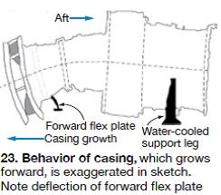
Concerning expansion resistive forces, the forward flex plate is not designed to accommodate casing expansion, which is in the direction of the compressor inlet (Fig 23). The water-cooled support leg anchors the gas turbine at the aft end. Expansion in the forward direction was confirmed by dial-indicator readings.
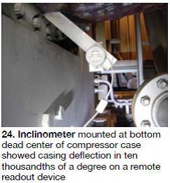 That the casing deforms there is no doubt as Myers and Anderson learned from an inclinometer mounted at the bottom dead center of the compressor case (Fig 24). The more negative its reading, the closer the S1 tip is to the R1 base. However, Myers pointed out, while casing deformation is a contributing factor in clashing, it has been happening for the entire life of the machine and clashing did not become an issue until corrosion products had years to accumulate and cause lock-up.
Another factor contributing to clashing is surge/stall events during shutdown (these have been verified with vibration readings) and possibly during startup as well. And Anderson believes weak spots in the casing, possibly cracks, may be yet another contributor. Myers had ultrasonic casing thickness measurements taken at the front ends of two Ceredo compressors. Data plotted on a 2-in. grid template revealed that some parts of the casing were as much as twice as thick as others. For example, casing thickness measurements for one unit extended from 1.406 to 2.820 in.; for the second unit, 1.355 to 2.840 in.

Anderson explained that the manufacture of sand castings is perhaps more art than science and precise control of thickness is not possible. However, he added, the internal diameter is precision-machined. Anderson provided the sketch in Fig 25 which shows a casing might be sufficiently thin in one or more areas to allow flexing, possibly cracking.
Myers next expressed his concerns about clashing, including these:
- Movement of a stationary vane may, over time, cause cracking conducive to failure.
- Bending of vanes during impact with rotating blades may be of sufficient magnitude to initiate failure.
- Impacts from blade/vane collisions may cause stress risers in rotating blades capable of cracking and blade liberation.
- A vane or blade failure at the front end of a compressor will result in corn-cobbing of the compressor and a huge repair bill.
What’s a user to do? GE recommends replacing vanes and ring segments with an attachment design change that is said to reduce the potential for vane lock-up. This requires rotor removal and is expensive, and may only be part of the solution given the multiple possible contributors to clashing noted earlier.
Myers came up with a much more economical solution: Free-up locked vanes with penetrating oil to mitigate the condition causing the change in resonant frequency. Ceredo technicians developed a delivery system and applied penetrating oil where vanes intersect ring-segment slots near the 6 o’clock position—the compressor location where clashing occurs most often because moisture accumulates there.
Lubrication of the vane attachment area does help, Myers and his Ceredo team confirmed by comparing vane clashing indications from one borescope inspection to the next. Application of a permanent dye to the leading edges and tips of vanes was critical to this determination (Fig 26).
Anderson believes a true clashing solution also involves the forward flex plate because it is restricting the normal forward expansion of the engine. One way to prevent the flex plate from interfering with engine expansion might be to unbolt the flex plate, preload it in the aft direction using jacks, and re-bolt. During engine operation the casing would expand and the flex plate would return to its unloaded condition, theoretically eliminating curling of the compressor casing. Anderson has proposed a test program that would confirm his solution—or not.
Both Myers and Anderson agreed that the optimal preventive measure might be cropping S1 vanes to the profile reflected in Fig 27 to create more clearance between the S1 tip and R1 base until an economical clashing solution is available. The tradeoff is the cost of some lost compressor efficiency versus the cost of a new compressor in the event of a catastrophic failure.
Summary of observations. The user community has learned a great deal from the work spearheaded by Myers and Anderson as the following points indicate:
- Data from the tests and measurements conducted on one of the Ceredo unis are repeatable, positive indication of their validity.
- Significant compressor disturbance occurs when bleed valves open at breaker opening.
- Casing deflection is in place on shutdown, not startup.
- Clashing most probably occurs during shutdown.
Rotor-life panel
Rotor lifetime inspection and life extension was a top concern shared by many of the nearly 140 conference attendees representing a global fleet of more than 1200 7B-EAs. Plant Manager Myers, who is responsible for six 7EA simple-cycle peaking units at Ceredo, moderated the “ask-the-experts” panel. There were no formal presentations, just a series of fruitful discussions between the attendees and the following panelists:
- Mike Burton, VP, First Independent Rotor Services of Texas (FIRST),
- Richard Curtis, VP engineering, Eta Technologies LLC,
- Chad Garner, manager of engine integration, PSM,
- Dr Ashok Koul, PE, president, Life Prediction Technologies Inc,
- Ted PapaGeorgiou, director of GT marketing, EthosEnergy, a Wood Group-TurboCare venture.
- Greg Snyder, engineering manager, Dresser-Rand Turbine Technology Services,
- David Taylor, engineering manager, Masaood John Brown International Ltd, and
- Paul Tucker, president, FIRST.
The panelists had considerable experience in the inspection, repair, and replacement of rotors and rotor components for GE frames. For example, Tucker has more than five-dozen end-of-life (EOL) inspections to his credit; Taylor, two dozen life assessments on Frames 5 and 6; Snyder and Curtis, several each. Koul’s company is known for its physics-based XactLIFE™ gas-turbine prognostics system, which incorporates materials-engineering-based rules to analyze the effects of mission and damage accumulation variability on component life.
One of a dozen or so users facing an EOL inspection within the next couple of years started the dialog, asking the panel, “What happens if you find nothing during the inspection?” Tucker replied, “It’s your decision, but essentially the unit is good to go. However, you need to set up a follow-on inspection program.” Keying on the “nothing” in the question, Koul said that each inspection technique has limits regarding flaw type and size and this must be factored into evaluation because it is a risk.
Someone asked if creep must be factored into the evaluation. “Yes,” was the short answer. Inspections for creep are the same for base-load and peaking machines, but creep would more likely lead to a catastrophic failure in a cycling engine than it would in a base-load unit. Regarding the latter, long-term operation at high temperature is conducive to creep-induced rubbing and vibration, a panelist noted, and if a failure were to occur it would be relatively “graceful” and contained by the casing. Curtis suggested that a focal point of a creep investigation should be wheel rims.
Another panelist said a goal of the inspection is to determine the life-limiting components on the rotor and replace them in a timely manner. Knowing when to replace requires good inspection results and an analytical component, he added. The challenge essentially is to manage both risk, which is escalating over time, and the maintenance/capital budget. Perfect segue for Koul, who said the tools exist to quantify risk.
A discussion ensued concerning onsite and in-shop inspections. Tucker said that preparations for an EOL inspection should include a site visit during the hot-gas-path (HGP) before the shop visit to record important data. This effort usually takes two or three shifts. Curtis followed by suggesting using in-situ inspection results together with unit operating history in a model to determine the most critical parts to inspect when you get to the shop.
Garner said PSM offers a lifetime management program for rotors made by Alstom and others; onsite inspections are part of that effort. Intimate knowledge of the rotor reduces risk, he said. PapaGerogiou recommended doing onsite inspections until an hours-based unit reaches about 150,000 hours, then move it into the shop.
Snyder recommended conducting an in-depth data gathering effort six months before shipping your rotor to the shop, perhaps earlier. Don’t rush the shop trip, he said, there’s plenty you can do onsite—for example, check for bucket rock, corrosion, creep effects, etc. Burton urged attendees to keep the plant budget in mind before making decisions. Don’t move forward until you have the information to support your actions, he said; until that time, keep running and making money.
A user said his plant, located in a remote area, bought a pre-owned rotor and had it refurbished. He wanted to know if this meant the operating clock got turned back to “zero hours.” No, a panelist said; they should have done an EOL inspection when they had the machine apart. Curtis then pointed out that creep damage is cumulative and you never get back to “zero hours.”
Discussion of replacement parts and spares followed. One thought: When buying replacement parts for a base-load unit, look to peakers as a resource because the damage mechanisms are different. Regarding spares to have on hand, be sure you know the idiosyncrasies and operating history of the specific rotor you’re trying to support. Rotors may look the same, but not necessarily so. You don’t want to buy and stock unnecessary part.
Next, the $64 question: What portion of the recommendations in a typical Technical Information Letter is commercial? One panelist guessed at 50% for the 7EA. For example, he said he was not aware of any failures on this engine having to do with the wheels. Other panelists agreed. However, he went on, insurance companies want to be sure end users are doing something to mitigate risk during these inspections.
Another panelist picked up on that point, adding that insurance companies advocate sending a rotor to the shop, having all the tests done, and setting up a follow-on inspection program. Their evaluations are on a case-by-case basis, he said, adding that insurers are not advocates of buying new rotors. A user asked, What about third-party versus OEM EOL inspections? The panel’s response: Third-party solutions for rotor life extension are to OEM specifications, but you avoid the high costs associated with OEM parts and labor.
One of the panelists posed a question that an owner/operator would ask: The third-party EOL inspection team found an indication that the OEM would have accepted “back in the day” and the machine has operated well for 25 years, should I worry? This is a realistic question given Tucker had said earlier that gas turbines dating back 25 years were not inspected to the level they are in today’s EOL inspection. Assuming the flaw you found had escaped detection until now, you have to answer the question with a “Yes.”
Just because the engine ran for 25 years in its current condition doesn’t mean it will make 26. Suggestion made: The models available to you can provide an informed answer, use them and pay attention to the results.
Curtis offered these positive words regarding a shop visit: It’s amazing how clean the actual forgings are when inspected. They are of high quality. Steel refining technology used was good, the forging process was good. You should not anticipate finding anything, but you have to look.
Koul urged the users to have the analytical experts set up the appropriate models with your rotor’s specific operating parameters and the information collected during the EOL inspection. Only then will informed decisions be possible. Snyder stressed the need for thermal analysis. Thermals drive the stresses, he said, and they impact life significantly. Fast starts, short shutdowns, etc, all are different operating scenarios that impact rotor life.
Tucker provided encouragement to those agonizing over a rotor EOL inspection. If you get good results from the boresonic inspection, you don’t have to unstack and conduct another such inspection again. Just do rim and other inspections during HGPs. A panelist offered this parting comment: Keep in mind that there are real good design tools to predict life after the 5000-start limit. The predictive tools available today are excellent.
Performance enhancement
Presentations on proven methods for increasing the output and/or improving the efficiency of gas turbines generally are well received by owners/operators. The steering committee invited two experts on performance enhancement to address delegates in Monterey: EthosEnergy’s Robert Burke and Mee Industries Inc’s Thomas Mee.
Burke covered water washing to assure high compressor efficiency, fogging and wet compression to boost power output, and automatic tuning and combustion dynamics monitoring to maintain gas-turbine (GT) performance at a high level. Mee, a globally recognized expert in fogging science and engineering, focused on his core expertise.
Burke began with the design highlights of the company’s patented water wash system, named EcoValue™, which uses the same basic technology as the EthosEnergy power augmentation system. In fact, the speaker said the company now offers combination systems for both water wash and wet compression (Fig 28).

The purple curve at the bottom shows the impact of parts wear and tear—such as casing deformation. This degradation is unrecoverable (you’re not going to replace a casing). The red curve represents such components as airfoils and seals which degrade but can be returned to “as new” condition when those parts are replaced during major inspections. Offline washes return performance to the red curve.
Depending on duty cycle, ambient environment, and other factors a plant may do from one to four offline washes annually. Frequent online washing—perhaps as frequently as daily—restores performance degradation from day-to-day fouling to the orange line. Each green line identifies an online wash.
Lenox next described a fleet-wide study to assess the impact of filtration on compressor health with the following objectives:
- Understand filter capabilities and impacts on compressor degradation.
- Understand the contaminants and their impacts on compressor degradation.
- Refine the definition of “filter life.”
- Establish a product offering encompassing both industry standards and compressor health.
Starting with a global installed filter base of more than 100 units, Lenox winnowed the field to 16 statistically significant sites equipped with the appropriate tools for meaningful data acquisition, statistical testing, and verification. Of the 16, two were in Europe, the remainder at six sites in the US. Two coastal units were in the mix, remainder inland. All but two of the gas turbines were 7FAs but the results are valid for 7EAs and other engines as well.

For the 7EA, locating spray nozzles halfway between the inlet struts achieves desired online cleanliness in three to five minutes at water flow rates ranging up to about 65 gpm. Fleet historical data indicate that engines washed daily produce an average of 1% more power than those that do not.
 Packaged water wash modules come in a range of sizes to serve gas turbines from about 10 to more than 200 MW. One module can accommodate up to four engines and can be controlled by operations personnel. Options include adjustable detergent flow control, automated detergent injection, data logging, etc.
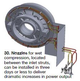
Wet compression can be accomplished by spraying water into compressor inlet air upstream of the gas turbine, or directly into the unit. EthosEnergy uses the latter approach (Fig 30) to assure tight control of droplet size at the compressor inlet and optimal control of the wet compression process, to prevent corrosion, attack of galvanized steel in the air inlet ductwork by demineralized water, etc.
EcoValue has 14 so-called “stalks” for injecting water into the compressor. They are arranged in pairs between adjacent struts; each stalk has two spray nozzles. Up to 90 gpm (2% mass flow) can be injected at 1850 psig. System typically can be installed in a 7EA over a weekend.
Burke described a power augmentation system serving four 7EAs at a 300-MW cogeneration plant in Texas which was commissioned shortly before the meeting in Monterey. Power generation increased by 11.5% and heat rate improved by more than 2.5%. There also was a small reduction in NOx output. Turnkey cost, the speaker said, was less than $100 for each additional kilowatt of capacity provided through wet compression. Operational control is via the existing DCS; no modifications were required to the turbine control system. Also, no tuning was needed and there were no combustion dynamics impacts.
Next, Burke described a “re-fogging” service offered by EthosEnergy to address any maintenance issues with an existing conventional fogging system—such as frequent failure of pump seals, loss of spray nozzle tips, oversaturation of inlet air, large droplets conducive to compressor damage, water flowing down the inlet drain and being wasted, etc. Goals are to improve reliability, maintain power and heat-rate benefits, and reduce maintenance cost.
CFD analysis and optimization of the existing array design generally is one of the first steps in the re-fogging effort. A new pump skid often is recommended if there are issues with the existing one. In many cases the number of pumps can be reduced and variable-speed drives used to improve performance.
Mee had not presented before the 7EA Users Group in some time and it’s doubtful that more than a very few in the room had ever heard him before. Recall that more than half of the attendees were participating in their first 7EA Users Group meeting. For those who had listened to this expert previously, the presentation was a beneficial review.
Not much new has happened in fogging technology recently—that is, at least how fogging is used in the electric power industry. However, on the commercial front, Mee reported that GE has no objection to the use of Mee fog systems on GE gas turbines provided the applicable TILs are followed.
Mee Industries has installed fogging systems on more than 800 gas turbines worldwide, nearly 200 on GE Frame 7s and 9s alone. The performance gain possible through fogging was the primary reason Mee Industries installed 25 systems on gas turbines in the last year; nine of those units were 7EAs.
Avoid trips on liquid fuel
With more than half of the owner/operators attending the conference running engines capable of burning oil, JASC Inc’s (Tempe, Ariz) system for verifying the integrity and readiness of the liquid fuel system, without test firing, was of considerable interest to attendees. Although a few of the users present had oil-only units, most operated dual-fuel machines for which the Zero Emission Equipment (ZEE) Performance Test was designed.
Back-up liquid fuel systems must be exercised regularly—typically monthly—to assure their reliability when needed. In some cases, the operator is following guidelines provided by the OEM, in others there’s a grid requirement. When exercising the system in the usual manner—either starting/running/shutting down on oil or starting on gas, transferring to oil, and then going back to gas for shutdown—remember that you (1) risk tripping the unit because of high exhaust-temperature spreads, (2) pay a premium for the test fuel, and (3) have to deal with the significant emissions associated with burning diesel fuel.
Schuyler McElrath told that group that JASC Installations LLC developed ZEE to improve the performance of back-up liquid fuel systems. Traditionally, he said, starting reliability of large industrial GTs on gas exceeds 97%, but it is only about 30% on distillate. For most applications, ZEE permits plant personnel to operate the back-up distillate system through the entire operational range of fuel flows and light-off to full-speed/full-load without actually burning fuel. All fuel-system components are operated and flowed using the GT’s electronic controls. All equipment in the fuel system is tested from the main fuel tank to the control valves at the fuel nozzles as part of the process.
McElrath reminded the group that liquid-fuel system components deteriorate from the effects of heat, showing photos of coking in a three-way purge valve and liquid-fuel check valve to illustrate one of ZEE’s benefits. That also was the perfect segue for the fuel system expert to talk about the company’s water-cooled liquid-fuel check valves and three-way purge valves to prevent coking and improve reliability. McElrath said JASC water-cooled liquid-fuel valves are now installed on more than 500 industrial engines worldwide and that the OEM is JASC’s biggest customer.
Air filters
Inlet air filters were uncharacteristically absent from the published program for the annual meeting; however, they were included in one of several open discussion sessions led by Myers, and there were more than half a dozen suppliers of this equipment at the vendor fair. Plus, there was a filter presentation by the OEM during the half-day GE fleet update.
Experience with HEPA filters was one of the first open-discussion topics. Recall that HEPAs typically cost several times as much as conventional filters but they have demonstrated an ability to keep compressors pristine without water washing. One OEM strongly recommended against water washing for a period of time and that created interest in, and sales of, HEPA filters. The OEM lifted its “ban,” following the development and commercial availability of compressor airfoils less susceptible to damage from water droplets and advanced washing systems with better control of droplet size.
One user said he ran a side-by-side test with HEPA filters in one 7EA and F9 filters in a sister unit. Both sets of filters were from leading manufacturers. The results: The HEPA filters were running well and the compressor they were protecting was very clean. The machine with the F9 filters “had a dirtier appearance.” Another attendee said the compressor on his unit with HEPA filters was running very clean and the pressure drop across the filters was “OK.” Sox prefilters blew off the final conical/cylindrical filters, leading the user to think they were ready to be changed. Two more attendees said they were getting ready to replace their conventional filters with HEPAs.
The subject of filter-life analysis was raised. Most participants said they sent their filters back to the supplier for evaluation—typically annually. The typical reply is “Run another year.” But one user’s report card said “You could benefit by replacement.” Two attendees reported positive evaluations on 10-yr-old filters. One was concerned about operating with such old filters and decided to change them anyway. He believed there was degradation of the filter medium.
The filter presentation by Jim Lenox of GE’s Air Filtration business, which was divested by the company shortly after the 7EA meeting (now a division of CLARCOR Industrial Air), recommended owner/operators ask about compressor health in terms of output and heat rate before making a buying decision, suggesting filter efficiency in itself doesn’t predict compressor health. Lennox began by making attendees aware that just because alternative filters under consideration for your replacement project meet the same EN779 or ASHRAE 52.2 specs for a given rating, it doesn’t mean they are equal for the specific application. In case you’re unfamiliar with the EN designation, it is the European filter specification akin to ASHRAE in the US.
The table presents a typical evaluation for three filters under consideration. Filter 1 features a cellulose blended media with nanofiber on the surface; Filter 2 has a synthetic media with nanofiber on the surface; Filter 3 has three layers—outer layers of polyester with fine fiberglass in the middle. All are rated F9 and are similar when compared to traditional industry standards. This type of data is what you would get in sales literature; however, it is not predictive of compressor health, as you can see in Fig 31, which illustrates how gas-turbine performance degrades over time.


Also important, 15 of the units previously were equipped with Filter 1 or Filter 2 and had data from those experiences. Plus, all the units in the study had ClearCurrent PRO (Filter 3) installed for at least six months, had performed at least two water washes, and were running more than 500 hr/yr at base load. ClearCurrent PRO (predictable, reliable output) was introduced to the industry at the end of 2012.
The results shown in Fig 32, Lenox said, illustrate that owner/operators can dramatically improve gas-turbine output and reliability with a comprehensive understanding of both filtration capabilities and the impact of contaminants on compressors. Real-time data feeds allow trending of compressor health and point to adjustments to maximize revenue potential.
Controls panel
Not to demean the importance of the more than 900 7EAs believed to be in service worldwide, but many of these engines—particularly those in the US—operate only when the more-efficient F, G, H, and J frames are not available. Bench players, as sports fans know, must hit the ground running and contribute positively to the team effort—now!
Same for the 7EAs; when called, they are expected to start immediately and run reliably. And they generally do, which is why they are valuable assets in any fleet. According to data available through the ORAP® database maintained by the engineers at Strategic Power Systems Inc, Charlotte, for the last six years E-class frames (7EAs included) have compiled the highest availability and reliability numbers among gas turbines in peaking service; yes, even higher than aeros.
With reliable starting and high availability the mission goals for the majority of 7EAs in the US, upgrade money invested in these engines often goes into the control system. That makes perfect sense. This market opportunity was not lost on the steering committee, which arranged a panel and one formal presentation on control systems, or on the suppliers and integrators of control systems that participated in the vendor fair.
The controls “ask-the-experts” forum, which focused on the reliability, maintenance/repair, and upgrade of legacy systems, featured some of the industry’s top subject-matter experts—specifically:
- Craig Corzine, president, CSE Engineering Inc.
- John Downing, CEO, Turbine Controls & Excitation Group.
- Kevin Kochirka, ABB Power Systems.
- Ricky Morgan, VP Engineering, Turbine Technology Services Corp.
- Randy Riggs, gadget master, Powergenics.
- Luke Williams, independent controls consultant.
- Peter Zinman, president, Gas Turbine Controls Corp.
EthosEnergy was visible by its absence. But there were several people already participating on the panel who could handle any question the users asked. Clark Weaver, controls program manager, and his team were highly visible during the vendor fair with the launch of the company’s icon™ control system brand.
ABB’s Kochirka was the only DCS supplier on the panel, although Emerson Process Management Power & Water Solutions, which participated last year, had a representative in the audience to answer any questions on Ovation. GE Measurement & Control participated in the special half-day OEM session where Carlos Scott, product line leader for Power Gen Control Solutions, and Ashok Acharya presented on “Controls Obsolescence and Cyber Security” (summary below).
The controls panel covered much of the same subject matter as the one in 2012, but with half of the 2013 attendees first-timers, the material was new and the perspective welcome. Also, last year’s panel was arranged differently: Participants made formal presentations and then a panel of the four speakers was convened for Q&A. The 2013 version began with a nominal three-minute biographical/company/product introduction by each speaker before the floor was opened for questions/group discussion.
The message from users heard loud and clear was the “unconditional love” they have for the Mark V control system. This was in sharp contrast to the negative dialog on the Mark VIe. Regarding the Mark V, comments included: “You can’t hack a Mark V.” “Great control system.” “Very robust.” “Cards are bullet-proof.”
Picking up on the positive vibes, one panelist said “Why would you want to rush to change the control system?” He said that the Mark V, in particular, has plenty of support; you have a lot of time to make a decision regarding your control system. Another panelist said his company had enough control cards to support users for the next 20 years. Also, that he would hold cards in storage and ship them to you as necessary for a modest service charge. When you do make the decision to go forward, one of the panelists suggested, specify an open system. In new system selection, go for minimum devices to maintain.
Maintenance, maintenance, maintenance was the suggestion from a panelist when asked how to assure long card life. His company offered cleaning and inspection services to keep control system components in top shape. He also stressed tight control of temperature and humidity inside the controls cabinet and proper removal, handling, and replacement of cards.
Lightning was a subject brought to the panel. A user asked how to mitigate its effects. The grounding system is critical he was told and the integrity of all grounding connections should be verified periodically. Cards can be irreparably damaged by lightning, but if they’re showing only one trace it probably pays to fix them.
An owner/operator asked how card functionality is verified after repairs. The panelist responding said his company puts the card in an energized panel and checks all functions—even for capabilities the user might not need. A report is provided for each repair made. It details components replaced and tests run to verify functionality. Mention was made that some owners want detailed data; that might add to the repair cost the group was told.
The panelists left the grey heads in the room believing they probably could get to retirement without having to replace their Mark Vs. But the report on HMIs wasn’t so positive. Early HMIs, attendees were told, are difficult to replace in kind but that’s not a problem, because there are far better alternatives today. The message coming across was that an HMI upgrade is a good investment. Two panelists, Corzine and Downing, indicated that they had done/were doing a significant number of HMI upgrades.
EthosEnergy’s Weaver picked a meaningful venue to roll icon. This was not a new product introduction but rather the christening of a field-proven solution that offers the functionality of GE Speedtronic™ Mark I through Mark VI control systems for Frame 5, 6B, 7E, and 9E engines. The open-platform solution, which uses Rockwell Automation’s PlantPAx system, ensures independence from single-source hardware and software support. It is compatible with both standard and DLN combustion systems and can be configured with integrated ECOMAX® functionality for combustion optimization and automated tuning.
The always approachable Weaver put on his promotional hat for a minute or two when speaking with the editors to tout the value proposition offered icon. He said it achieves the following:
- Defeats control-system obsolescence.
- Improves plant operational flexibility.
- Provides a single controls solution for the entire plant.
- Reduces control-system lifecycle cost.
- Eliminates costly service and support charges associated with “locked” DCS systems.
OEM on controls obsolescence. The general feeling among owner/operators of GE gas turbines regarding control system obsolescence is that the OEM wants its customers to migrate to the Mark VIe, period. This conclusion is drawn from discussions among participants in user group meetings and between the editors and users. While this may still be GE’s goal, the “one size fits all” attitude that may have existed no longer does, Carlos Scott (since reassigned by the OEM) told the owner/operators and the editors at the 7EA meeting.
Scott and the members of his controls solutions team are well aware of how “attached” many users have become to the Mark V and they support that product loyalty by now offering these three options for owner/operators:
- Continue to run Mark V controls, via the Mark V revitalization program that leverages the plant’s existing parts inventory and an enhanced OEM support package, to give your system another five years, or more, of quality performance.
- Migrate to Mark VIe by replacing key components with ones modified to allow use of the existing Mark V cabinet. Field wiring remains as is; installation and commissioning are completed in five days.
- Migrate to Mark VIe with a full cabinet replacement. What you get is an all-new DCS platform with the latest controls technology and cyber security, alarm reduction, fully automated starts, device manager, thermal performance monitoring, HRSG stress and life monitor, etc.
The first option provides 24/7 technical and parts support until 2019, at least. To ensure reliable life extension, GE technicians inspect your system and remove/repair or replace boards considered marginal and perform other maintenance as required. The customer has the option of using its personnel for routine troubleshooting and maintenance going forward.
With the second option, the Mark V is upgraded to Mark VIe capability through a simple plug-and-play exchange of electronic modules, as shown in the photos. With no change to site wiring, panel terminations, turbine field devices, or panel size, the migration significantly expands control system capabilities—such as use of OpFlex, ability to support DLN combustion, upgrade to redundant Ethernet for both I/O network and external communications, etc—while addressing obsolescence issues. This option is available for all frame engines, but not aeros.
Advantage of the third option, migration to the Mark VIe with complete cabinet replacement, is like “starting over.” Forget about the documentation you can’t find, the ground faults you can’t locate, etc. Those and other problems disappear. Bear in mind that the Mark VIe embraces a different technology than the Mark V. It’s not rack-based, but rather a flexible and open control system designed to industry standards with all the enhancements noted above, plus I/O expansion capability and distributed I/O, lifecycle support, Windows-based HMIs, etc. CCJ
EcoValue’s wash nozzles produce droplets with diameters ranging from 80 to 250 microns (mean droplet size, D43, is 156 microns) when operating within the pressure range of about 900 to 1200 psig at a water temperature 140F. Droplets larger than 500 microns are viewed as harmful and are avoided. Nozzle placement, as determined by CFD analysis is the same for both online and offline washing (Fig 29).