


Comprehensive hazardous spill mitigation strategy
Best Practices Award
Challenge. Rokeby Generating Station consists of three legacy frame gas turbines and one black-start diesel/generator with a total plant capacity of 245 MW. The site also has two thermal storage systems with associated refrigeration equipment. Rokeby’s original GT operated only on fuel oil but with plant expansion, two dual-fuel units were constructed and the older unit was converted to be dual-fuel capable.
Even though the generating units normally burn natural gas, there is a 5-million-gal fuel-oil storage tank onsite which is supplied by an intrastate pipeline. The site also supports miscellaneous equipment with various types and quantities of oil and other fluids. As part of the spill risk mitigation program, Lincoln Electric System evaluated how to protect the environment from a large oil release from either the storage tank or the pipeline.
Solution. There were two fundamental approaches to the spill mitigation strategy: (1) onsite containment and (2) offsite containment. The onsite containment strategy was implemented in three phases (Fig 1).
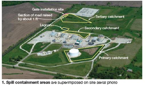
Second, the geography of the site allowed for construction of containment gates on drainage structures. A relatively small drainage ditch which runs along the east side of the plant’s switchyard provided adequate storage for turbine or refrigeration system fluids or GSU oil releases. A manually operated slide gate was installed on the associated 2-ft drainage culvert.First, the spill containment berm around the storage tank was re-engineered and expanded because the original containment capacity was less than 5 million gallons.
Further “downstream,” three 4-ft culverts provided a final opportunity to keep any spills from leaving the site and entering a stream located directly next to the plant’s property line. An engineering analysis indicated a plant road that ran along the site property line, next to the stream, could be used as a containment dam by installing three manually operated, 6 x 4-ft slide gates on the existing culverts. The analysis also determined that by raising the elevation of a 150-ft section of the road by approximately 1 ft, the containment could be increased from 1.38 to 2.32 million gallons.
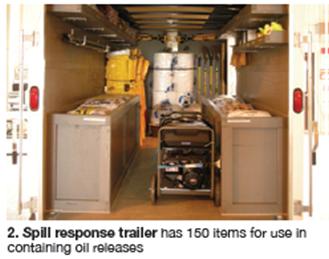
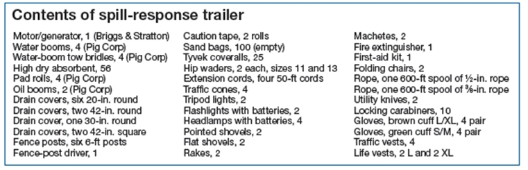
Finally, if a spill does make it offsite to the stream, the plant has put together a spill response trailer with 150 items (Fig 2) that can be used to contain oil releases on moving water (sidebar). Plant personnel periodically hold spill-containment exercises which helps them identify the best access points along the stream to intercept a spill, as well as how to properly deploy the spill containment equipment.
 Project participants:
Bruce Barnhouse, plant manager
Joe Komenda, project engineer