


Cycle chemistry critical to operational success
Attendance at the Australasian HRSG Users Group (AHUG) annual conference has been growing by about 30% year over year and if that trend continues there should be about 80 participants at the upcoming meeting in Brisbane (Sidebar), more than enough to support the small exhibition planned. By show of hands, approximately half of the attendees at the 2010 meeting were present in 2009; three quarters were owner/operators of combined-cycle plants.
 Presentations at the first two conferences were well received and the discussion was robust. The mid-December timing of this year’s meeting is perfect for many combined-cycle and cogeneration-plant owner/operators in North America. The fall overhaul season will be over; plus, it will be summer inAustraliawhile snow likely will be falling inCanadaand the northern US.
The general format of this conference is to have two days of invited presentations and open discussion followed by two four-hour workshops on the third day. Last year, workshops were presented on FAC and P/T91. The report on the 2010 meeting that follows is based in large part on notes taken by David Addison, principal, Thermal Chemistry Ltd, Horsham Downs, Hamilton, NZ, for exclusive use by this publication.
AHUG III
 December 13-15, 2011
BrisbaneConvention & Exhibition Centre
Register today: www.ahug.co.nz
The annual meeting of the Australasian HRSG Users Group (AHUG) provides a forum for sharing knowledge and experiences among owners, operators, manufacturers, service providers, consultants, and others with an interest in heat-recovery steam generators and associated plant processes and equipment.
The group’s steering committee, chaired by Dr Barry Dooley of Structural Integrity Associates Inc, has the following members:
- Bob Anderson, Competitive Power Resources.
- Gary Joy, CS Energy.
- John Rickerby, Contact Energy.
- Lester Stanley, HRST Inc.
- David Addison, Thermal Chemistry Ltd.
- Daniel Cole, Origin Energy.
- Des McInnes, Tarong Energy.
Conference program
The 2011 meeting begins with two days of presentations and discussion on the following subjects, among others:
- Heat-transfer components and pressure parts.
- Tube failure mechanisms, including FAC and thermal fatigue.
- Water treatment/cycle chemistry.
- Piping systems.
- Structures/ductwork, dampers, stacks.
- Valves.
- Duct burners and their support systems.
- Controls.
- Environmental systems.
- Balance of plant.
Two four-hour workshops are scheduled for the third day. The morning is dedicated to a review of nondestructive examination (NDE) tools and processes available to identify the known failure and damage mechanisms in HRSGs. Included are case studies to illustrate the applications.
The afternoon workshop focuses on attemperator design, control, and maintenance best practices. It begins with a summary of in-service problems associated with desuperheaters and describes how to monitor and evaluate attemperator performance.
Dissimilar metal welds. A discussion session on pressure parts opened the meeting. The first question came from a combined-cycle owner/operator wanting to understand what issues might be associated with welding P91 end caps to P23 headers.
But before an answer was given, some in the group wanted to know why there would be need for such a dissimilar metal weld (DMW). A boiler engineer mentioned that P23 allows a thinner header wall and more favorable tube spacing than P91 but that it might be difficult to obtain end caps of P23. He said use of the correct filler material was critical to weld reliability based onUSexperience in coal-fired boilers.
The discussion migrated to the suitability of hardness testing for DMWs. One consultant blurted, “Yes!” But a fleet manager was not in full agreement, rating field hardness testing of the heat affected zone (HAZ) as “not too useful.” She thought replication was better, plus ultrasonic testing for crack detection.
Another plant representative poured cold water on the latter idea, saying the clearances were so small access for UT was difficult at best. The group generally agreed that most pressure parts in an HRSG are very difficult to get to.
A well-respected metallurgist opined, “Hardness testing can be useful if you’re able to compare back to baseline data with the sample analysis method and hardware. However, you must be careful not to do hardness testing on theHAZ, because those data would be meaningless.”
The advantages of doing a mock up of P23/P91 DMW creep-life destructive testing were noted. However, it was pointed out that this was particularly expensive.
Gas-side fouling received some air time, with an eclectic group of predictable comments, including these:
- Do a pressure-drop survey before and after cleaning to gauge effectiveness.
- Dry-ice and compressed-air blasting are most effective for deposit removal; avoid water.
- High back-end temperatures adversely impact efficiency and power output.
- It’s really important to get deep into tube bundles with cleaning nozzles, although this can be difficult because of access issues. Good advance planning was stressed.
- Document and trend the amount of debris removed after each cleaning.
- Important to manage gas-side moisture during unit shutdowns. This should be considered at the specification stage to assure access for dehumidification equipment.
- Measure and record the rate of deposition above and below the dewpoint temperature.
Long-term layup was another topic brought before the group. A user wanted to know how to prevent equipment degradation. A powerplant chemist took the microphone first. Of primary importance, he said, was to be sure the unit is fully drained (drain with residual pressure on the unit for best results) and a flow path of dry, warm air has been established. He warned about non-drainable areas of the boiler. If this is your first dry layup, the chemist continued, you’re likely to find some. Before passing the “mike” he suggested controls on personnel access to prevent parts scavenging.
A boiler consultant suggested the use of vapor-phase inhibitors to protect metal surfaces. He said they have been used successfully in theUS. A word of caution: Important to flush the unit before returning it to service.
The idea of wet layup didn’t get much support. Proper layup, a chemist said, requires HRSG modifications to enable offline circulation, dosing, and monitoring, and these changes militate against a rapid return to service. It’s absolutely critical, he added, to manage wet layup “by the book.” Detailed procedures and strict control of chemistry are critical to success.
High-energy piping
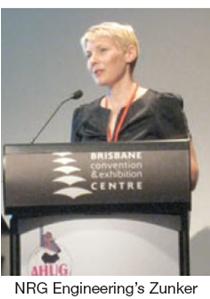 Director Anita Zunker of NRG Engineering Ltd made the first formal presentation of the meeting, “High-Energy Piping Systems: Inspections and Weld Repairs,” which held the group’s interest at a high level. There was something for everyone: piping inspection methods and experience, weld prep, weld repair of similar and dissimilar materials (P91, P22, Type 304H stainless steel), field welds, shop welds, etc.
Zunker’s presentation was based on work NRG did at two 400-MW-class, single-shaft combined-cycle plants owned by Contact Energy, the second-largest electricity generator inNew Zealand, according to Wikipedia. Otahuhu B Power Station, which began commercial operation in 2000, has P91 throughout its high-temperature circuits: superheater (SH) and reheater (RH) harps and main (HP) and hot reheat (HRH) steam piping.
Taranaki Combined Cycle Power Plant has Type 304H stainless steel in its highest-temperature SH and RH harps;HRHsystem has 304H piping connected to a P22 desuperheater, connected to P91 piping to the steamer; 304H HP piping connects to P91 piping to the steamer.
NRG’s involvement came after a P91 tube to P22 header weld failure at Otahuhu triggered the start of a P91 inspection program at the plant. There had been no significant P91 weld inspections conducted in the first 10 years of that facility’s existence. By contrast, some condition assessments had been initiated at Taranaki after five years of service (the plant’s previous owner, Stratford Power Ltd, was acquired by Contact Energy at about that time).
Weld inspections at Otahuhu revealed a cornucopia of problems: stress relief cracking, high-hardness weld metal, low-hardness elbows, incorrect filler metal, weld defects, ovality in elbows, high levels of cavitation in transition areas between HP and HRH stop valves and piping because of poor weld detailing and transitions, and unqualified procedures for thermowell DMWs.
At Taranaki, Risk Management Solutions’ ranking methodology was used to identify highest-risk DMWs. Inspections were conducted of (1) selected 304H welds, (2) 304H to P91 HP welds, (3) selected P91 HP welds, and (4) FAC risk areas. Inspection of the 304H welds revealed an undocumented weld, wall thicknesses heavier than nominal, fatigue cracking, cracks in downstream welds, etc. Replacement 304H welds were full-thickness gas tungsten arc welds (GTAW) to minimize grain size and improve the effectiveness of ultrasonic testing.

The 304H-P91 HP weld identified as the highest-risk weld in the plant revealed no findings. However, the long-term risk is carbon migration across the ferritic/austenitic interface. The 304H-P22 HRH weld using Inconel filler metal revealed surface cracks in the Inconel on the stainless steel side of the weld (Fig 1). Surface defects were dressed and have not reappeared.
Lessons learned. Zunker compiled a list of lessons learned regarding weld inspections, which she shared with the group:
- Nondestructive examination
- Work closely withNDEcompany to understand limitations of test methods.
- Clearly advise what types of defects you are suspicious of.
- Be sure that any test restrictions—for example, ultrasonic testing of stainless steels—are properly understood.
- Report results promptly.
- Replication
- Where wall thinning is a concern, the position of replication will have to move if repeated.
- Where wall thickness/weld profile is inconsistent, the replication location should be prioritized to thinner areas.
- Material degradation is not immediately problematic if not associated with creep cavitation.
- Risk areas
- Undocumented welds.
- Section changes.
- High-stress locations (local effects sometimes can overwhelm global stresses).
Best practices regarding P91 repairs include the following:
- Know baseline hardness of components.
- Remove all aged weld metal and theHAZwhere possible.
- Ensure gentle transitions where section changes.
- Follow welding procedure specifications without deviation.
- NDEbefore post-weld heat treatment (PWHT) to minimize the risk of unnecessary heat-treatment cycles.
- Develop a detailed PWHT plan, including close monitoring of temperatures on and adjacent to the weld—particularly if any section changes or difficult geometries are involved.
- Carefully plan when to remove restraints. Avoid loading of welds not yet stress-relieved while ensuring adequate flexibility for expansion during PWHT.
Desuperheaters
It’s difficult to imagine an HRSG technical conference without attemperator issues on the program. The topic is “must cover” subject matter, along with cycle chemistry (including iron transport), dissimilar metal welds, and P91 issues. At AHUG II, V N Hari Babu of Control Components Inc presented a primer on desuperheaters, “HRSG Interstage Attemperation—Challenges and Future,” which was of greatest value to attendees with less than about five years of deck-plates experience. For the others, it was a reminder of some challenges met and conquered and a catalyst for follow-on discussion.

Babu divided his presentation into three sections: desuperheating technology, typical problems/challenges, and design solutions. He began with a flow diagram that put everyone on “the same page” regarding terminology. Fig 2 illustrates the typical locations of interstage attemperators: between the primary and secondary superheaters in the HP circuit and reheaters (RH). Terminal attemperators sometimes are installed after the final stages of the superheater and reheater as well.
Interstage attemperators are responsible for controlling steam temperature in accordance with startup and steam-turbine-inlet requirements, and also for preventing thermal damage to superheater and reheater tubes in the highest-temperature harps as well as damage to outlet steam piping and downstream equipment. Two additional points to keep in mind:
- Terminal attemperators are not intended for use after startup.
- In some cases, interstage desuperheaters are not installed and attemperation duty falls to the final or terminal desuperheater.
Atomization physics. Proper atomization and evaporation of the spray water supplied by an attemperation system is necessary both for good temperature control and to prevent water carryover (access “Avoid desuperheater problems with quality equipment, proper installation, tight process control,” Fall 2004, at www.ccj-online.com). The complete integration of injected water into superheated steam involves three steps: primary atomization, secondary atomization, and evaporation.


Primary atomization is the breakdown of water into droplets by the attemperator’s nozzles. Goal is to create as small a droplet as possible regardless of the water spray flow rate. Variable-area nozzles offer this capability, Babu said (Fig 3). They provide good primary atomization even at relatively low flows. Fixed-orifice nozzles, by contrast, are sized for the maximum flow rate and do a progressively poorer job of atomization as water flow decreases. Reason is the inherent reduction in differential pressure that is characteristic of reduced flows through fixed-area nozzles.
All droplets created by mechanical atomizers are not of the same diameter, Babu told the group. The size and shape of the droplets varies with injection velocity and nozzle geometry.
Secondary atomization refers to the break-up of large droplets by the dynamic force of the steam flow. However, for secondary atomization to occur, the dynamic forces acting on a droplet must be greater than the viscous forces holding the droplet together.
To achieve good secondary atomization, Babu suggested injecting the water spray perpendicular to thesteam flow, not parallel to it (Fig 4). This maximizes the relative velocity between the liquid droplets and the steam flow and ensures efficient secondary atomization under all operating conditions. Plus, turbulence in the steam flow is enhanced, which can increase the evaporation rate by as much as an order of magnitude.
Evaporation. The small droplets produced by secondary atomization boil and evaporate. “Small is beautiful,” the speaker stressed. The time to complete the evaporative process depends on the total surface area of the water volume and is proportional to the square of the droplet diameter. Any droplets that do not evaporate before reaching the temperature sensor may wet the sensor and make it difficult to control steam temperature as intended.
Inadequate design of the attemperation system can result in a combination of poor control and poor atomization during transients that would permit carryover of water into harps, damaging headers and tubes.
The primary design requirements for a proper attemperation system are the following, Babu said:
- Control final steam temperature accurately.
- Assure reliable and repeatable tight shut-off on high-pressure letdown lines.
- Provide high turndown capacity/rangeability (50:1) of spray-water flow to maximize efficiency.
- Accommodate thermal quenching of mechanical parts.
- Avoid issues associated with the natural frequency of probe-type desuperheaters (von Karman vortex street).
The speaker touted the benefits of the pipe-style multi-nozzle desuperheater, with control-valve element separate from the attemperator as shown in Fig 4 (CCI’s design, of course). Having nozzles installed circumferentially around the desuperheater body ensures full distribution of spray flow across the steam flow and good primary atomization regardless of spray-water flow, he said.
This design eliminates damaging vibration from von Karman vortex street effects, he said, as well as damaging bending moments from high-velocity steam—both of which adversely impact nozzles that extend perpendicularly into the flow stream.

A thermal barrier (Fig 5) is critical to achieving the goal of the fourth bullet point immediately above. It separates the hot and cold working elements to mitigate the intensity of the thermal cycles experienced by critical spray-nozzle components.
A proper liner helps by (1) increasing steam velocity (by virtue of its smaller diameter) and improving secondary atomization, (2) creating vortices that improve atomization and enhance mixing, and (3) assisting with heat transfer and evaporation (Fig 6). Here are some rules of thumb Babu offered for liner design in superheater and reheater insterstage attemperator applications:
- Minimum length of straight pipe upstream of the liner should be three pipe diameters.
- Length of straight pipe downstream of the liner should allow a residence time of 0.067 sec for spray water to evaporate, if the mass flow of spray water is less than 15% of the mass flow of superheated steam. If more than 15%, allow 0.1 sec.
- Location of the temperature sensor should be at a distance downstream of the liner that allows 0.2 sec of residence time to ensure complete mixing of the evaporated water and superheated steam. However, if the mass flow of spray water is greater than 15% of the mass flow of superheated steam, the residence time should be increased to 0.3 sec.

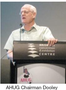
Discussion. Chairman Dooley asked attendees how many had interstage attemperator problems and what they were. Here are some of the replies:
- Cracking of the HP P91 desuperheater liner, though caused by a misaligned spray nozzle. Cracks were identified in the HRH attemperator as well.
- Plant inspects desuperheaters regularly. Some cracking observed between spray-nozzle penetrations.
- Many problems over the plant’s 12-yr life—including liner and nozzle cracking. Now into the fourth iteration of attemperator design.
- An engineer employed by a HRSG manufacturer reported seeing many problems in his career and based on that experience recommended careful inspection of attemperator components each outage. Issues this attendee was familiar with included the following: valves installed backwards, plant personnel trying to cool down units by running attemperators and severing tubes at their headers, logic/control issues, cracked liners, etc.
He added that HRH systems tend to have more problems than HP systems regarding attemperator performance. His company is fitting drain pots downstream side of all attemperators, and on the upstream side of superheater attemperators as well, to minimize condensate slugging issues.
- Root cause investigation, another participant offered, requires a close look at attemperator spray flow over time, upstream/downstream (of the attemperator) temperatures, and spray-water control valve position. Trending of key DCS data is important to identifying potential issues before they develop into full-blown problems.
- Attemperator problems are not confined to combined-cycle plants, an O&M supervisor reported. Overspray by desuperheaters on coal-fired has forced water into heat-transfer surfaces of those boilers as well.
Cycle chemistry
There were several discussion sessions on cycle chemistry during the two-day meeting. What follows are brief summaries of those exchanges among attendees.
Iron sampling and analysis. A question to the group by one of several chemists participating in the meeting: Who’s doing iron sampling on their units and what methods are they using? The first colleague to respond said the sample at his plant was taken from a wet-rack grab point and analyzed ICP (inductively coupled plasma spectrometry). The discussion recognized IC (ion chromatography) as another method for determining the amount of iron in a given sample, but only for very low levels of the metal.
Another chemist said iron sampling in HRSGs is very difficult because of limitations in sampling systems, cooling water, and the lack of sampling points. Composite sampling is the best, he added, but if not, grab-sample total iron will suffice as a rough indication. The value of composite sampling was supported by another chemist. Yet another said iron analysis is very difficult to do—in particular because of low flows and pressures—and results must be validated.
 Particle-size counters are another method, someone said, but the group was not sold on the idea. Results must be carefully validated because there are many sources of particulates in a powerplant that may not be iron. Attendees were told by Dooley that the IAPWS (International Association on the Properties of Steam and Water) is now recommending 2 ppb total iron in feedwater and 5 ppb in HRSG drums. Dooley is the IAPWS executive secretary.
A consultant pointed to the difference between the heat fluxes in the HP and LP drums and asked why the latter was restricted to 5 ppb iron. Dooley said that with the relatively low heat fluxes in the LP system, deposition is less an issue so the “rule of 2 and 5” wouldn’t necessarily apply there and the LP evaporator could be cycled up to more than 5 ppb.
A powerplant engineering manager asked “why bother to do iron if you think your chemistry is as optimized as possible?” Dooley responded that cycle chemistry improvement is a continuous process. Even if you believe your cycle chemistry is optimum, he said, you should still do iron at least semiannually to ensure that baseline conditions remain stable. It’s part of a best-practices cycle-chemistry operating program, he added.
The group discussion on iron continued after a prepared presentation on inspection and assessment of high-energy piping. A chemistry consultant for an HRSG OEM asked, “What are the potential sample contamination issues with iron sampling, and errors with analysis?”
Contamination is unlikely if iron sampling is done correctly, he was told. Regarding the second part of the question, the detection limit depends on the analysis method. Dooley added that the analysis method is critical and low-level ICP-based methodology is required.
Tube sampling. Next question: “Would correct iron sampling replace the need for boiler tube sampling?” Dooley responded with an emphatic, “No!” Two aspects, he said: Once you’ve achieved optimum chemistry, iron monitoring is only necessary every six months. Tube sampling and analysis still is necessary to confirm that HP evaporator chemistry is operating correctly.
Dooley then added that owner/operators should not rely only on HRSG tube samples to determine boiler condition. Chemistry monitoring—online and grab—are very important as well. Both tube samples and monitoring are required to assure the correct assessment of conditions.
The next day. It seemed there was no getting away from chemistry, and the discussion continued the next morning with an initial focus on sample monitoring. The life span of instruments was one topic. A chemist said not all analyzers are created equal and that sample flows can be challenging for low-pressure stages, requiring the need for booster pumps in some cases. Another attendee talked about the importance of proper installation and set up of instruments, proper grounding being one concern.
LP evaporator. The subject of LP evaporator carryover issues was raised and these questions were asked: “Are others experiencing carryover?” If so, is it doing any damage to the drum? One colleague said his plant had a distribution issue, an insufficient number of risers, and a need to improve steam separation. He was asked, “Any issues with superheater corrosion?” No, because plant is using only tri-sodium phosphate, so there’s no risk of acid phosphate corrosion in the superheaters.
The carryover issue was identified during commissioning, the group was told: A classic warranty claim that the OEM was reluctant to resolve initially but has since the meeting by making internal drum modifications under warranty. Carryover of up to 2% was detected at times (such as during load changes) based on the IAPWS method. That calculation is said to be easy.
A boiler design consultant who had inspected the unit said it was poorly designed and that some baffling should correct the issue. Would increasing the drum pressure—and, thereby steam density—help, the inspector was asked. The short answer: “Likely.” Another boiler engineer said he would not recommend using cyclones in an LP because they might not work under all operating conditions.
Condensers. It may seem counter intuitive to include condensers in a discussion session on water treatment—until you get a condenser leak. The first user to the microphone wanted to know the experience of others in the room regarding the lifetime management of titanium condenser tubes and inspection processes used to assure tube integrity.
A chemist warned, “Never assume that your titanium-tubed condenser will not leak.” One user said his plant eddy-current tests about 10% of the tubes each outage (different tubes every year). Plant has not identified any issues yet. Ultrasonic methods can be used as well but users said they’re slower than eddy current.
Another chemist with vast international experience reported that several titanium-tube issues are experienced by powerplant condensers each year. When these failures occur in combined-cycle systems, HRSGs are at serious risk. The expert suggested having a level of instrumentation and monitoring to detect issues quickly. Monitoring drum cation conductivity is one of these.
The first chemist took control of the “mike” again, suggesting that condensate polishers would provide some measure of protection against a condenser leak. The second chemist disagreed; too expensive, he said, owners won’t go for polishing. However, analysis work by the first chemist has shown that the inclusion of a condensate polisher in a combined cycle from Day One is economically viable. This has been validated at a plant in New Zealand.
Getting to the root cause of a leak can be challenging; correcting the deficiency, expensive. An engineering manager for a combined-cycle owner said he suspects the tube cracking problem in one of his company’s condensers was caused by high-energy steam from the turbine bypass system entering through the heat exchanger’s side wall without proper baffling in place to protect the tube bundle against direct impingement and resulting vibration. The condenser likely will require re-tubing, he said, or redesign and then re-tubing.
Another user said the tightness of tube support plates is critical to preventing tube vibration during bypass operation.
Long-term lay-up was revisited, but this discussion focused on under-lagging corrosion of steam-system components, such as pipe and valves. A consultant from theUSsaid he knew of plants in lay-up for eight years without such problems; however, the HRSGs and steam system were located indoors.
An Aussie user recalled bringing an HRSG out of long-term lay-up with no internal issues but significant corrosion of surfaces covered with insulation. He believes it’s important to remove the insulation to verify satisfactory surface condition. Another possible consideration: Insulation degradation from long-term exposure to moisture.
The chemists were not to be denied their opinions. One urged users to check carefully their water treatment plants during the restart. Another reminded the group to check chemical analyzers as well. Yet another chemist backtracked, reminding plant personnel to run demin water through their analyzers before laying up the unit.
Chemistry manual. There were four formal presentations after the second morning’s discussion session on chemistry, but as soon as the final speaker left the podium there was another round of open discussion on chemistry. Interestingly, the chemists never seemed to tire, leading one to believe that as a group they’re in better shape than powerplant O&M personnel. The chemists chased the microphone around the room at a full gallop.
The first question put the chemists in full command of this session. One asked innocently: “How many plants represented here today have a site chemistry manual?” Personnel from four or five plants said they had one; one plant borrowed it from the chemical service provider; another four or five didn’t have one.
Dooley turned on his microphone looking somewhat distressed. Not good, he intimated. World-class operators have chemistry manuals that were developed specifically for their plants and not derived from generic OEM documents. These reference resources must include all the details of the cycle chemistry program—including specifications, targets for analytical measurements, troubleshooting guidelines to deal promptly with emergency situations, etc.
He was right, of course, and the chemist who asked the question was there to reinforce the chairman’s message. The chemistry manual, he said, is particularly valuable for the guidance it gives operators in the identification of off-scale events and the knowledge it provides to deal with such events confidently.
The engineering manager for a new Australian plant said they have a detailed asset management plan for chemistry and an alarm action guide to assist operators in troubleshooting. He didn’t have any “saves” to discuss because the program was still in the fine-tune stage. Come toBrisbanein December and get an update.
The environment manager for another Australian combined cycle stressed the need for clarity and simplicity when developing a chemical manual and troubleshooting guide for operators. It’s important how the information is presented, he said, urging his colleagues to have a single, clear page of chemistry information on a given topic together with a trend analysis.
A chemist described her experience at a plant with a small staff. Alarm review there is critical, she said. It’s vital that operators get correct alarms. As an assist, the plant has an electronic alarm analysis system to accelerate troubleshooting and proper training has made the operators comfortable with it.
Out of the blue, a representative of a water-treatment solutions firm redirected the conversation back to iron transport. He asked how attendees were removing iron. One participant said that a condensate polisher works well in low-temperature systems. Another uses cation resin as an iron filter for 160F condensate.
Two additional questions closed out the chemistry discussion. They were:
- Who is doing resin testing? Reply: No lab inNew ZealandorAustraliaequipped to do this in a reliable and timely manner.
- An alumina refinery chemist asked if anyone had experience in changing from amines to ammonia. He has a cogen plant with condensate returns to the HRSG at about 300F. The response from a senior chemist: There’s no real advantage gained by using blended amines over the correct application of ammonia. The science of their chemistry is well understood and published in literature.
Suppliers say amines offer an advantage in distribution into the liquid phase. But blended amines can mask cation conductivity, making cycle chemistry control more difficult and possibly contributing to greater deposition in the HP evaporator—the area of greatest risk. Each site needs to assess the advantages and disadvantages of each based on their specific requirements.
Miscellaneous topics
With the final formal presentation over and the conference winding down there were a few questions on miscellaneous topics that had not been addressed over the two days. These included the following:
Cold-case cracking. An asset manager asked how others were handling cold-case cracking issues—specifically repairs. A boiler designer with significant HRSG inspection experience said he has seen such cracking but not often. A metallurgist asked if the crack morphology had been determined, but it hadn’t—at least not yet. The only information the questioner could provide: There was a whitish deposit in the crack area. Perhaps this would be a viable discussion for a future meeting when there are more cold-weather operators are in attendance.
Tube repair. A general question for the group from the technical support supervisor at a combined-cycle plant: “What are your thoughts on the best methods for HRSG tube repair—tips, tricks, etc?” An asset manager said the most practical approach for their plant was to cut out the tube and plug. “Why not replace the tube?” an experienced plant manager asked. Reply: No spare tube available and their welder was not confident in making a full weld given the access constraints.
That led the plant manager to ask the group a question: “How many of you do not have spare tubes available?” Answer: Four or five stations by show of hands. A new discussion thread opened on the importance of spare tubes and how to store them to prevent metal attack. A boiler OEM noted the importance of holding spares, especially if you have an unusual tube size.
Back to the asset manager challenged by the inaccessibility of tubes that failed most often at the bottom of the unit. An engineering manager suggested cutting an access port in the side of the HRSG. A boiler engineer recommended retaining a selection of short bare tubes with the proper bends onsite for tube-to-header repairs.
For bottom failures, he continued, you can cut the drain lines and swing panels out of the way to give just enough space. You also can cut risers to swing panels, he added. EPRI was mentioned as having some excellent repair methodologies, although the contributor was not sure they were fully commercialized yet.
Chemical cleaning. One participant said regarding pre-service cleaning there is no trend for or against: It’s a preference thing based on experience or lack thereof; some endorse the idea, some don’t. He added that most post-service chemical cleaning inAustraliawas carried out after a failure caused by bad housekeeping or bad hydro water. Traditional solvents and acids were used in the cleaning processes.
A poll of the group revealed about 20 hands for having done pre-operational cleans; three or four, post-service. The most difficult post-service clean was one involving seawater ingress and traders who wouldn’t take the unit offline for repairs until two weeks after the tube leak occurred.
A couple of chemists had these comments: (1) The full pre-operational chemical clean offered by one of the major OEMs was said to have been very effective. The process is conducted with a full chemical clean of the water and steam circuits and then with the plant in bypass mode until iron level in the hotwell meets a stringent specification. (2) Chemical cleaning is a best practice globally and well proven. Avoid at your own peril. The risk of deposits in the HP evaporator is very well understood today.
Finding tube leaks in HRSGs. Final question of the day: “Is anyone using compressed air to search for tube leaks in superheaters and reheaters? A plant manager turned consultant said he had experience with the practice in conventional boilers and used an acoustic gun to locate the high-frequency sound. He waved a red flag on air pressure: Too-high pressure, he said, could be a safety hazard. The person asking the question agreed, noting that it can be very difficult to locate HRSG reheater leaks without a compressed-air “tracer.” CCJ