


CCJ ONscreen launches webinar series for plant O&M personnel

The steam turbine incorporated into a combined-cycle plant produces about one-third of that facility’s power. At most large combined cycles, all the steam that does work in the turbine must be condensed and returned to the cycle; none is used for process and/or space heating as it is in smaller CHP (combined heat and power) systems.
Water is selected most often for condensing duty, although air-cooled condensers (ACCs) are increasingly favored for powerplants in areas where water supply is a concern (see article, p 76).
Condenser circulating-water systems are categorized as either once-through or closed-loop. The former take water from a natural source (lake, river, ocean, etc), pump it though the condenser, and discharge the heated water back to its source. Once-through systems, the predominant method of condenser cooling years ago, are specified much less frequently today because of environmental concerns.
Mechanical-draft wet cooling towers (Fig 1) typically are selected to reject heat from closed-loop systems serving combined-cycle plants. The two designs used most often are the induced-draft counterflow and crossflow towers (Figs 2, 3).
In the competitive generation business, top plant performance is critical to success. Proper operation of the heat-rejection system is particularly important in this regard because of its direct impact on the efficiency of electric production. Operating a condenser above its optimal pressure because the circ-water temperature is too warm reduces the plant’s revenue stream.
David Brumbaugh, president, DRB Industries LLC, Broken Arrow, Okla, told the editors that operators frequently ask him on plant visits, “Why am I not getting the thermal efficiency that other plants do and what can I do to improve my performance?” Sometimes, he said, the problem is rooted in less-than-satisfactory cooling-tower maintenance practices. A little more digging may indicate that roving operators do not fully understand what performance gremlins to look for, and where, when checking their cooling towers on rounds and when inspecting them offline.
Brumbaugh, a frequent speaker at user-group meetings, and an expert in adiabatic cooling and cooling-tower applications with more than 15 years of experience in the combined-cycle sector, was asked by the editors to develop a “lunch ’n learn” webinar on cooling towers. The goal: Help technicians with less about five years on the deck plates make a positive contribution to the plant’s bottom line by reducing cooling-tower losses.
The program, moderated by Senior Editor Scott Schwieger, will air in early December (see schedule in sidebar) and will be divided into four 10-minute segments, each followed by Q&A. Brumbaugh developed the content from his hands-on work helping plants improve performance and reduce operating costs.
Several other “lunch ’n learns” will be announced shortly, including one on cooling-water treatment, which is not part of Brumbaugh’s presentation.
Getting top performance from wet cooling towers
Listen to David Brumbaugh while eating lunch and pick up some pointers on how to be more effective in monitoring cooling towers on rounds and how to conduct the proper offline inspections to maintain top performance. Cost is only $49 per screen. Yes, that includes the large screen in your plant’s conference room. There the entire staff can listen in and ask questions online, for just $49.
The same program will air live on Wednesday, December 7 and Friday, December 9. It will be hosted at 11:30 a.m. East Coast time on December 7. On Friday, the program will be conducted twice at 11:30 a.m. Midwest time and again at 11:30 a.m. West Coast time. Of course, you can participate on either of the two days and at either of the broadcast times if lunchtime in your area is not convenient.
Register today at http://www.ccj-online.com/onscreen/cooling-towers
Questions? Contact program moderator Scott Schwieger, scott@ccj-online.com
Program helps improve cooling-tower performance
An overview of Brumbaugh’s performance enhancement program for mechanical-draft cooling towers is presented below. The starting point is routine inspection of the following four components/sections common to powerplant towers: heat transfer, water distribution, structural, and mechanical. This is suggested reading before participating in the seminar. An abridged glossary is provided as well. Understanding key words and phrases beforehand facilitates participation.

1. Heat transfer.
Brumbaugh refers to fill as the “business end” of the cooling tower. Its job is to promote contact between air and water for the longest time possible with the least resistance to air flow, thereby providing the exact evaporation rate required to cool the water. There are two types of fill: splash and film. Both can be used in crossflow and counterflow towers, but film fill is used almost exclusively in the former.
Splash-type fill breaks up the water by interrupting its vertical free fall with successive offset levels of parallel splash bars. Maximum exposure of the water surface to the passing air is achieved as the water breaks up into smaller and smaller droplets on its way down to the cold-water basin.
Film fill causes the water to spread into a thin film over a large area to maximize its exposure to air flow. It has the capability to provide more effective cooling capacity than splash-type fill within the same amount of space. However, film fill is very sensitive to situations where the circulating water can become contaminated with debris (primarily trash, scale, and algae/slime) and probably should be avoided in those instances. There are some clog-resistant fills but their heat-transfer performance drops the more spacious their design.
Spash-type fill is sensitive to inadequate support (sagging allows water and air to channel through the fill in separate flow paths, impairing thermal performance), while the most popular film fill, made from PVC, can be damaged over time by sunlight’s UV rays.

In addition to looking for collapsed or sagging splash fill, and for brittle failure of PVC film fill, O&M personnel should take notice of the gaps between adjacent sections of fill. A smooth interlocking fit is desirable. Large gaps militate against effective break-up of falling water droplets, sections of media that are squeezed together can restrict air flow.
Drift eliminators remove entrained water from air pulled up through the fill to prevent both its impingement on fan blades as well as its release to the natural environment. The modest pressure drop through the mist eliminator benefits efficient operation by promoting uniform air flow through the fill.
O&M personnel periodically should verify the condition of drift-eliminator elements. If they are in poor condition or plugged, one or more of the following can happen: water carryover may occur and damage fan system components and/or infrastructure downwind of the tower; water consumption can increase; efficiency can drop because of lower air flow through the tower.
Inlet louvers are installed on virtually all crossflow towers but on only some counterflow towers. Their primary purpose is to retain circulating water within the tower. Closely spaced, steeply sloped louvers promote good water containment but resist the free flow of air—so there’s a design tradeoff there.
Operators on winter rounds should check for reductions in air inlet area caused by snow and ice, which obviously would restrict air flow but could damage louvers as well. Buildup of dirt and other debris in the inlet louvers also can reduce air flow and cause a loss in efficiency.
2. Water distribution.

Crossflow towers are characterized by a gravity flow distribution system. Condenser discharge water, delivered to a hot-water distribution basin above the fill, flows by gravity through metering orifices in the floors of the basins and is distributed across the fill.
Counterflow towers normally receive hot water from a pressurized main equipped with up-spray or down-spray nozzles. Nozzles must be checked periodically to verify the proper spray pattern; clean or replace nozzles as necessary. Keep in mind that algae and sediment that collect in the cold-water basin, as well as excessive solids that get into the cooling water, can clog spray nozzles. Having good water distribution across the entire tower is important to achieving the desired heat-transfer performance.
Basins hot and cold must be maintained clean, sealed, and structurally sound. Periodic visual inspections should be assigned to the O&M staff. Plant personnel also should check the performance of circulating-water pumps and flow control valves regularly.
3. Structural components.

Structural components–casing, structure, fan deck, stairways, ladders, walkways, handrails, etc—must be continually checked for integrity and repaired as needed. Deteriorating wood framework, in particular, is conducive to serious problems if not maintained in proper condition.
Many combined-cycle plants have retrofitted old wood structures with FRP (fiberglass reinforced plastic)—a high-strength/lightweight material that doesn’t corrode and won’t support combustion (Figs 4, 5). Deck boards, beams, flat sheets, angles, square tubes, channels, etc, are available in FRP and can reduce the life-cycle cost of a conventional wood tower.
The casing should be inspected regularly. Look for and repair leaks, cracks, holes, general deterioration, etc, that can contribute to leakage of air and/or water. Make sure hardware is tight.
Structure should be examined for metal attack, wood deterioration, tight bolting, etc. Check wood members carefully for decay. Tap with a hammer and if you don’t hear a high-pitch sharp sound your wood probably has seen better days. Probe soft spots with an ice pick to gauge remaining life.
Fan deck is important to maintain in sound condition because it supports maintenance activities vital to the reliability and efficiency of the tower. Remember that loose deck overlays are a tripping hazard and should be replaced or fastened appropriately.
Stairways, ladders, handrails, and interior walkways are critical to personnel safety and must be kept in top condition. Inspect with a sharp eye for evidence of wood decay, steel corrosion, loose treads, loose fasteners, etc.
4. Mechanical components.
The fan system includes the motor driver, gearbox, fan, fan cylinder shroud, and associated drive shafts, seals, couplings, etc. Perhaps the two most important indicators of fan-system health are gearbox oil quality and vibration level.

Charging gearboxes with top quality oil and maintaining the correct fluid level is the first step. Periodically (quarterly or at least semiannually) sample the oil and send it to a qualified lab for analysis. Water and particulates can dramatically reduce the lifetime of gears and these contaminants should be maintained at same levels in your gearboxes as they are in your turbine sump.
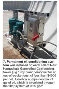
Two ways to remove water and particulates from gearbox oil are to mount the filters and water absorbent on a wheeled cart which can be moved from cell to cell (Fig 6) or permanently install the oil conditioning gear on the fan deck (Fig 7).
 Installation of a vibration monitoring system reduced cooling-tower gearbox failures at Morgan Energy Center, earning the plant staff a 2009 Best Practices Award for O&M (Fig 8). Goal was to have a method for warning of potential failure. The OEM provided a motor vibration limit switch used to trip the fan when excessive vibration is detected on the mechanicals. But it is of limited value to a staff charged with minimizing maintenance expenses and ensuring the plant can produce its design capability as required.
Installation of accelerometers allowed continuous monitoring at the shaft and gearbox end of the fan assembly(A).
The accelerometers provide accurate electrical signals representative of the vibration being monitored, thereby enabling a proactive and predictive maintenance program for the gearboxes.
Shaft and gearbox vibration readings are taken at regular intervals. Online historical trends comparing baseline readings can be used to detect abnormal operating characteristics (B).
In addition to monitoring vibration, roving operators should be checking seals for oil leakage. Periodically, when the cell is out of service, verify that backlash and endplay are within acceptable limits and that the drive system is properly aligned and bearings are snug.
Visual checks of the fan proper are imperative. Fans can lose blades (Fig 9). Check fixed-pitch blades for cracks, corrosion, and erosion; examine the connections between the blades and hub; and verify tightness of the bushing between the hub and shaft. For adjustable-pitch fans, periodic measurement and adjustment of the pitch angle to the manufacturer’s specs is needed as well.

