Six steps to successful repair of GT components
ContentsStep 1: How to assess the condition of GT parts onsite |
Editor’s note: Hans van Esch, founder of Turbine End-user Services Inc (TEServices), developed this primer on the six critical steps for refurbishing industrial gas-turbine parts, using material from his respected three-day training course, “Metallurgical Aspects of IGT Component Refurbishment.” First published as a series in consecutive issues of the COMBINED CYCLE Journal between 2Q/2005 and 1Q/2006, “Six Steps” was updated in September 2014 because of ongoing demand for the information. It is presented here in its entirety.
Step 1
How to assess the condition of GT parts onsite
 Owners and operators that take a proactive role in defining industrial gas turbine (IGT) repair and coating requirements ensure receipt of quality refurbished parts at a competitive price. Plus, top-quality components are conducive to maximizing the time between overhauls, thereby reducing O&M costs.
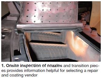
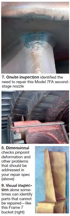
Refurbishment of components should begin with parts inspection and condition assessment at the plant before disassembly (Fig 1). The information compiled is helpful in selecting the repair and coating vendor, developing the repair and bidding specifications, and avoiding rework caused by fit-up problems.
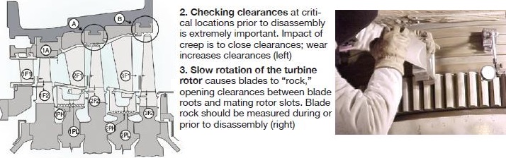
Checking dimensions. Before removing any parts, check clearances at critical locations (Fig 2). Recall that hot-section components are subject to creep, which causes them to deform and reduce as-built clearances. This is especially true for unsupported components exposed to high temperatures and stresses—such as shrouded blades (second-stage buckets) and second-stage vane segments (a/k/a nozzles), so-called shroud lifting and downstream deflection (DSD).
Wear can increase clearances beyond those recommended by the OEM (original equipment manufacturer). It occurs most often where a rotating part rubs a stationary component, such as at blade-tip and angel-wing locations. Wear also results from prolonged slow rolling of the turbine rotor on turning gear. So-called “blade rock” is caused by an increase in clearances between blade roots and the mating root slots in the wheel (Fig 3). The problem gets worse with time as shutdowns accumulate.
In most cases, manuals provided by the OEM describe in detail how plant staff can measure clearances, shroud lift, DSD and blade rock. Alternatively, a repair vendor or IGT consultant can assist plant staff. The data gathered, coupled with a thorough visual inspection, helps determine if dimensional correction is necessary. Such work can involve blade-tip and angel-wing restoration, DSD correction, restoration of blade clearances (shroud blocks and blade tip heights), and/or application of an anti-rock coating.
The information compiled also is valuable in the verification both of dimensions taken during the repair vendor’s incoming inspection and of its proposed repair process. Doing the job correctly the first time avoids unnecessary repairs, late deliveries, and time-consuming fit-up problems during reassembly.
When evaluating the proposed repair process, avoid the temptation to save money by taking shortcuts. For example, restoration of a component and not its matching partner (such as bucket and shroud block) can lead to problems during startup and/or abnormal operating conditions and not performing rejuvenating heat treatments can shorten the ultimate usable life of components.
Regular borescope inspections are valuable for periodic monitoring of parts condition. Findings can be confirmed and any deterioration—such as deposits, erosion, oxidation, corrosion, melting, wear, impact damage, etc—can be better evaluated with the naked eye or with aid of a magnifying glass when components are disassembled (Fig 4). Keep in mind that visual inspection by itself can be misleading and should be used primarily as a tool for identifying areas in need of further assessment with NDE (nondestructive examination), dimensional inspection, and metallurgical evaluations.
Evaluation of information compiled during the visual examination and dimensional checks is particularly helpful for identifying damage that may require further analysis before final decisions are made regarding parts replacement or reconditioning. When component deterioration is so severe that it dictates the overhaul cycle, a root-cause analysis (RCA) is in order. This should be conducted before any work, such as cleaning, is performed on the components that might compromise the investigation. Detailed operating data is needed to fully understand why the damage occurred.
Your repair vendor may be capable of such metallurgical analysis. If not, an independent laboratory can conduct the damage assessment. The laboratory selected should have a good understanding of IGTs in general, as well as specific knowledge of your engine type and running conditions. Such analysis often provides guidance on how to improve component performance, the required inspection cycle, and ultimate usable life. Thus the repair work specified and the selection of a coating to accommodate actual operating conditions should increase the life of the part and extend the time between overhauls.
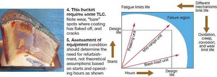
Importance of operating history. The actual number of starts, type of shutdown (normal or trip), and hours of operation are used by the OEM to determine when it believes an overhaul is necessary (Fig 5). This calculation can be further defined based on theoretical assumptions such as firing temperature and fuel. It is not in the best interest of most owners and operators because results often suggest overhaul earlier than may be necessary. When overhauls are governed by an OEM’s long-term service agreement, you may have no other option.
However, absent an LTSA, a better method might be to base overhauls on the actual condition of critical components. Plot your assessment of component condition (based on NDE, dimensional check, metallurgical evaluation of coating and base material, mechanical testing, etc) against operating conditions (fired temperature and hours, starts, etc) and identify the component that is driving the need to initiate an overhaul. Develop a plan to extend the operating life of this part through better weldment, coating selection, heat treatment, etc, thereby extending the time between planned outages.
Key to this approach is the development of a meaningful database. Carefully track and record the operating history of all critical parts, making sure to include such information as parts coatings and base materials, hours at temperature, use of water or steam for emissions control and power augmentation, etc. Access to such an information resource facilitates decision-making on outage scheduling, identification of components to repair and those to replace, etc, based on your plant’s actual needs. Currently there are software programs and online maintenance services available to assist the IGT operator with this.
Step 2
Preparing meaningful component repair specs
Preparation of component repair specifications is the first step in vendor selection and these specs should be part of your bid package. The specs also provide a framework for evaluation of work in progress and for conduct and verification of critical inspections from receipt of parts by the contractor through project completion.
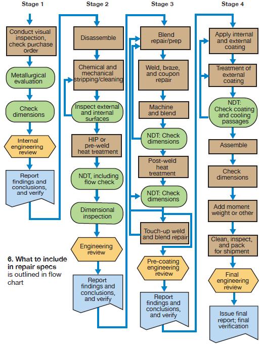
Existing specifications from previous repairs or end-user organizations are a good starting point for developing the specific component repair specs you need for the next overhaul. If you have no experience in writing specifications and have no good examples available for reference, call a knowledgeable colleague or an IGT consultant specializing in this work. Avoid “help” from repair facilities that might be on your bidders’ list. The flow chart (Fig 6) lists some of the items you’ll want to include.
Key to your specification development is information compiled during visual inspection (Fig 7) and checking of clearances (Fig 8) discussed in Step 1. Also, factor in previous repair experience with the same components and the experience of others on similar parts—things you might have learned at a user-group meeting, for example.
To ensure quality work, divide the repair process—and your specs—into logical stages. You want the repair facility to report its findings and recommendations after each stage and not proceed with the work before you or your representative approves. In most cases, dividing the repair process into the four stages illustrated in the flow chart will produce positive results. The steps are:
-
-
- Stage 1 Receive and conduct the initial inspection.
- Stage 2 Disassemble components, clean/strip, heat treat, and inspect.
- Stage 3 Repair, heat treat, and inspect.
- Stage 4 Coat, reassemble, and make a final inspection.
-
 Stage 1: Receive, inspect. Start your repair specification with receiving, where the parts are visually inspected to ensure that no handling and transport damage has occurred. Individual parts should be identified and marked, and match the shipping and purchase documentation. Dimensional and visual inspections are next, followed by disassembly.
Flow testing of internal cooling circuits with rod, water, or air should be performed at the beginning of the repair process to obtain data before possible plugging of these holes during cleaning and other operations. Visual inspection during early work can confirm the repairability of a component (Fig 9) before more cost is incurred. This also assists in selecting sacrificial parts—those from which representative metallurgical samples will be removed.
Metallurgical evaluation is vital for characterizing the base material to ensure that standard heat treatment will be successful in regaining desired properties post repair. Sometimes special heat treatment—such as hot isostatic pressure (HIP)—is required to make parts serviceable.
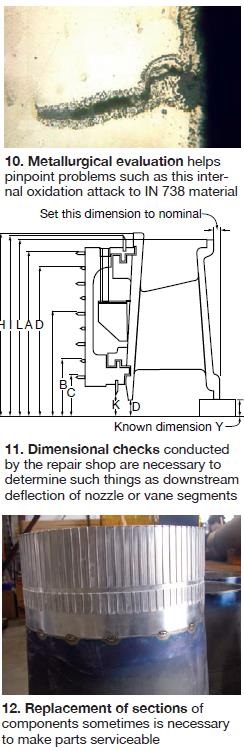
External and internal (cooling cavities) surfaces also require evaluation. Consider these possibilities: The internal coating can be in such good condition that stripping and recoating may not be necessary. By contrast, uncoated internal surfaces can be so heavily attacked by oxidation that oxidation products penetrate the grain boundaries (Fig 10) and ultimately form cracks that reach the external surface.
Evaluation of the external surface can reveal if the coating system provided the required protection for the component or if another coating is required. In the case of uncoated external surfaces, the amount of degradation can be determined; it must be removed before repairs are made or the coating is applied.
Following incoming inspection and metallurgical evaluation, an engineering review should be conducted with the owner or its representative present. Both parties must come away from that meeting confident that the original scope of work still will result in the desired outcome. Adjustments in cleaning, stripping, repair, and the coating process can be made, if necessary; worst case is that components must be scrapped.
Stage 2: Disassemble, clean and strip, heat treat, inspect. A more thorough inspection of parts received for repairs requires disassembly and removal of hardware—such as core plugs, impingement sleeves, etc. This work makes the surface accessible for cleaning, stripping, and heat treatment without risking damage to other areas of the component.
Most of the coating generally is removed by chemical stripping. Then the external surface can be inspected by heat tinting or macro-etching, so any remaining coating and oxidation/corrosion products can be identified and eliminated by blending.
Important: Specify tight control stripping/cleaning processes to avoid unnecessary thinning of the component.
 NDE. Preparation of components should include standard pre-weld solution heat treatment for nickel precipitation and cobalt-based superalloys. Occasionally, metallurgical evaluation also suggests the need for specialized heat treatment. Note: For many alloys such as OEM-patented materials, no published heat treatments are available and that combined with non-standard coating and diffusion heat treatments, the metallurgical condition and mechanical properties can differ significantly among repair vendors.
When specifying the type of NDE for your components, keep in mind that ultrasonic (UT) and eddy-current testing (ET) can detect sub-surface indications and, therefore, may have advantages over visual inspection and liquid-penetrant testing (PT). Also, these technologies can determine wall thicknesses at critical locations. Once again, the inspection team should verify that cooling passages are open.
More detailed dimensional checks are required at this stage—such as determining the downstream deflection of nozzle or vane segments (Fig 11). This step completes the so-called “incoming” inspection and another engineering review with the owner, and/or its IGT consultant, is recommended to ensure that the scope of work still will provide the desired outcome.
Stage 3: Repair, heat treat, inspect. The repair process can start after a component is cleaned/stripped, solution heat-treated, and inspected. In most cases, gas tungsten arc welding (GTAW)—also called TIG (tungsten inert gas) welding— is used for repair, although more and more facilities also use brazing for component restoration, mostly driven by need to reduce cost.
Keep in mind that while weld methods and filler materials are comparable throughout the industry, braze repairs are proprietary processes. This makes it especially important for you to define in your spec if brazing is allowed and where and under what circumstances it can be used. Also, inspection after prepping the components for welding and brazing, and after application and heat treatments, is important to ensure the desired quality is achieved. Note: Lately, cost-aware (or driven) repair facilities, including OEMs, are replacing PT and visual inspections with visual inspections only.
Replacement of sections of your components—so-called “coupon repair”—sometimes is required to make the parts serviceable (Fig 12). The replacement material should have metallurgical condition and mechanical properties the same or better than the original. The vendor’s quality system must be capable of ensuring that correct chemistry and other properties are within specifications.
Post-weld heat treatments that follow the repairs should be combined with the heat treatments required for coating application and diffusion. Important variables in the heat-treatment process include time on temperature, furnace atmosphere, and heating/cooling rates. Note: The heat treatments should not negatively influence the metallurgical condition and mechanical properties of the base material and should be discussed and agreed upon prior to repair being released by the customer and/or its IGT consultant.
Be aware that vendors sometimes subcontract heat treatment and other critical process steps requiring detailed instruction on their execution. When preparing repair specs, ensure that your company has access to its components at both the contracted repair facility and all of its subcontractors until the reconditioned parts are returned after project completion.
Before coating and reassembly is permitted, yet another inspection is necessary. This is especially critical for items that cannot be inspected or corrected later in the repair process because of heat-treatment, coating, or assembly issues. As for the preceding steps, another engineering review is suggested here to decide if coating and assembly should proceed.
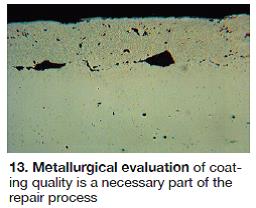 Stage 4: Coat, assemble, inspect. The application process is as critical to coating performance as the selection of the proper coating system. Your spec should address so-called “first-article” qualification, process repeatability, and final inspection. Coating quality should meet specification requirements and be as good as that demonstrated on the same or comparable component during the qualification trial. Metallurgical evaluation of the qualification sample should be part of the verification process (Fig 13).
The application procedure must lend confidence that this result can be repeated as many times as necessary without question. Quality checks should be conducted to verify process repeatability.
After coating and inspection are complete, component reassembly can proceed. During reassembly, dimensional checks are necessary to ensure proper installation of core plugs, wear strips, etc. Final inspection should include dimensional verification, like area and harmonics checks of nozzles, moment weight and sequencing for blades, unrestricted internal cooling passages, and visual confirmation of a job well done.
The repair process can be considered complete after the repair vendor’s final report is received and accepted. It should include all certifications, inspections, and engineering recommendations. This information is important should problems arise. Also, it provides valuable input to repair specification development for the next overhaul.
Step 3
Selecting the appropriate vendor to refurbish turbine parts
When selecting a repair facility to refurbish parts for your IGTs, keep in mind that cost—the variable upon which many decisions are based—is only one of several important considerations. Shop capabilities, experience of employees, vendor performance on similar jobs, quality control, sharing of technical details and documentation, communication, and other factors are equally important—perhaps even more so.
A thorough evaluation of alternative service companies is critical to selecting the best repair facility for the work required in support of your next outage. The sector of the IGT services industry concerned with parts refurbishment is dynamic and it is common for shops to be acquired, relocated, expanded through acquisition, or closed with little or no public disclosure.
This can have major impact on repair quality, so don’t assume the facilities that did an acceptable job of repairing compressor, combustor, and hot-section parts for your last outage are necessarily the best partners for the next overhaul. Likewise, a company rejected previously may have acquired new capabilities, hired new people, etc, and deserves reconsideration. The competitive nature of the IGT-based generation business suggests the need for continual monitoring or recent audit of service companies.
Every experienced plant and maintenance manager has his or her methodology for evaluating alternative repair shops—procedures that may differ depending on the IGT component, work to be performed, and schedule. For someone with limited vendor auditing experience, the guidance offered here for evaluation of (1) experience and reputation, (2) in-house and subcontractor technical capabilities, and (3) human resources and management systems, will help you get started. The scorecards provided are particularly valuable and should be customized to suit your specific requirements.
Experience and reputation. Generally, it is in your best interest to select a repair facility with experience both on your type of IGT and on the specific components requiring refurbishment. Such experience helps the end user because the service provider has a better understanding of the condition of the components, what the critical dimensions are, what the typical damage and failure modes are, which coating systems will provide the level of protection desired, etc.
If a candidate facility does not have direct experience on your machine, perhaps it has done comparable work on models similar in design, base material, and coating and cooling systems. The facility’s reference list of projects completed over the last three to five years pertinent to the work you require should contain adequate detail for follow-up (check the references with your colleagues), due diligence, and decision-making.
 Valuable insights on the performance of repair facilities can be gained by interviewing the candidates’ customers—past and present. One of the most important things to learn is how the prospective facility resolves quality issues. All repair facilities will run into problems at some point, but how quickly the company communicates and responds to problems, and the methods it uses to address them, is of vital importance to you.
Your interviews will reveal that most repair facilities are willing to develop repair methods and coating applications to suit specific needs. This is positive; however, if your components are the first articles repaired by a new method, more time and resources must be put against this effort than required by a proven procedure. And don’t forget to consider the end-user’s risks associated with any new procedure.
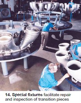
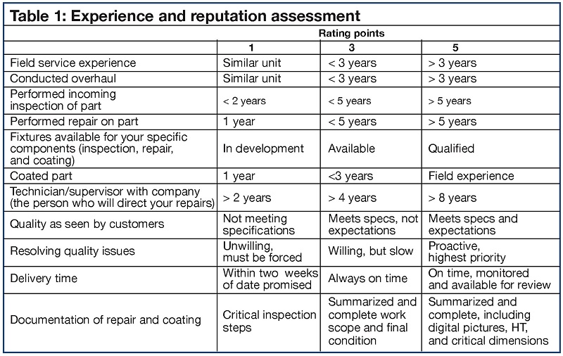
As part of your assessment, be sure to inquire about the fixtures available to facilitate the inspection and repair of components (Table 1). Fixtures can pay dividends in the inspection of complex components, such as transition pieces, (Fig 14), while reducing shop time and accuracy of the required check to be performed. Also, the availability of fixtures offers an indication of how much work a particular shop does, or has done, on specific components for a given IGT model.
Record-keeping is another area to investigate. After repairs are complete, you want documentation on the condition of your components (ID by serial number) “as received” and “final,” in addition to certifications for important process steps—such as heat treatments, stripping, coating, shot-peening, and most important of all, critical dimensions before and after repair.
During the request-for-quotation process the evaluation of repair facilities can be confirmed. Facilities with good experience will come up with some intelligent questions and offer some options to reduce the costs or prolong the lives of your components.
Technology and subcontracting. The assessment of IGT components conducted as part of Step 1, and the repair scope developed in Step 2, provide information of value for determining the optimum technologies for parts refurbishment. At this stage, keep in mind that it is not always necessary to apply the same coating system provided by the OEM on new parts. For example, in the past, MCrAlY often was applied on advanced blades and buckets with LPPS or VPS; today, however, HVOF-applied MCrAlY typically is used for repairs, and even new parts.
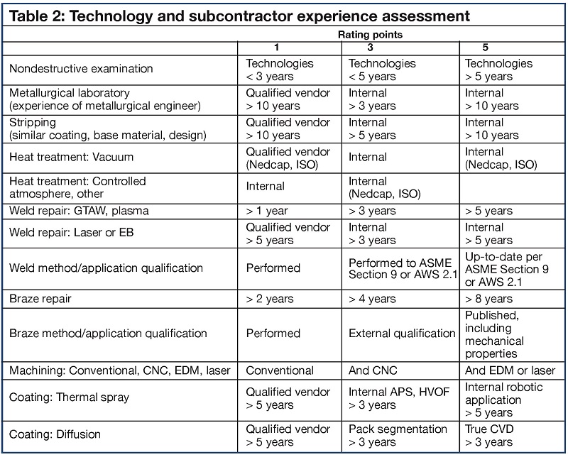
Information gathered from the onsite visual inspection, and from the AR (as-received) condition NDE and metallurgical inspection at the repair facility, sometimes suggests a customized repair and coating solution that can reduce the expected cost of refurbishment and/or extend the service life of components. Make sure you don’t miss an opportunity for competitive advantage by selecting a service provider that will partner with you to advise unselfishly on repairs and coating systems (Table 2). An independent IGT consultant could also be helpful in this.
Refurbishment of IGT components for late-model machines often requires sophisticated stripping, cleaning, repair, coating, and inspection technologies that are expensive to install and support. Thus many shops are not equipped to perform all these processes and steps in-house for all IGT models and they rely on subcontractors for certain tasks. To illustrate: Chemical stripping of IGT components poses environmental and health concerns and is often subcontracted to a specialty shop. Recently, however, the most experienced subcontractor was taken over and later closed down for these same reasons, leaving the repair facilities scrambling for an alternative.
To have certain repair or coating steps performed by a specialized subcontractor can be advantageous. However, your repair facility is still responsible for final product quality and must monitor the subcontractor to ensure conformance to specifications. This requires expertise on, and experience with, a process not present at your vendor. And, since the subcontractor is an extension of the primary company, it should be audited as part of your capabilities assessment.
Human resources and management systems. In the early 2000s, competition in the IGT services sector forced the closure or sale of marginal companies and drove out of work many capable engineers and repair technicians. Some of these people joined forces and started small specialty shops, contributing to the relatively large number of repair facilities—well over a dozen in the Houston area alone.
Small shops do not always have their organizational charts, job descriptions, quality manuals and systems, procedures, and qualifications in place. Important to remember with respect to small organizations is that an experienced core staff is capable of performing quality repairs and coatings at a competitive price on specific GT components. However, if the repair process increases in complexity—as it does for advanced components—or when the organization grows too quickly, quality issues can arise.
When turn-around time is important, a small company may not have the resources to repair and coat components to meet your schedule. On the other hand, larger companies may not always give the attention that you and your components deserve. Sometimes the best result can be achieved by dividing the component repair and coating work to multiple small, specialist facilities.
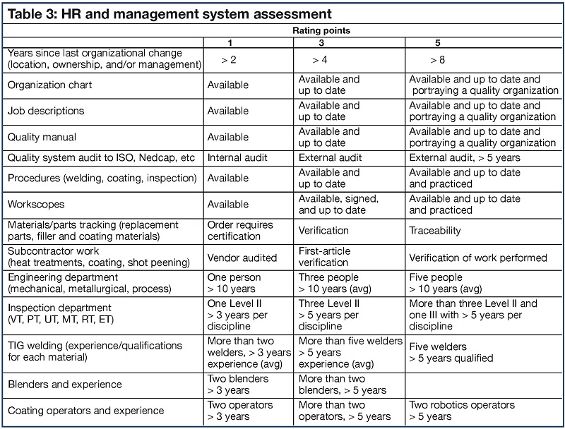
When conducting vendor assessments, be mindful that training and qualification of inspectors, welders, blenders, and other technicians is the foundation for quality work. The scorecard presented in Table 3 offers a valuable reminder of items to investigate.
Important to remember: OEMs recently acquired some of the independent repair facilities—losing in transition experienced and knowledgeable human resources, and transforming the organization to OEM “standards.”
Another market dynamic: Some end users have found the most competitive and capable independent repair shops filled during outage season, because of the increased number of engines in service and the higher GT capacity factors resulting from retirements of coal-fired plants. Several repair facilities responded by increasing shop space and staff. The negative impact for a few: Overcapacity, a buyers’ market, and smaller profit margins because expenses remained roughly the same. Cost-cutting to boost profit margins can have a negative impact on quality.
Step 4
Key stages in the repair process
Initial inspection. After assessing the condition of GT components at the plant site, creating repair and coating specifications, and selecting the repair vendor, your parts can be released for refurbishment and recoating. The first of four stages in the repair process is confirmation of, or assessment of, component condition (refer to flow chart included in Step 2).
This involves taking dimensions in the as-received and assembled condition at the repair facility, as well as conducting a visual inspection and a metallurgical evaluation. An engineering report reviewing all findings should confirm that the scope of work will produce the desired end product. If discrepancies occur, the end user or its representative should review the components, inspection reports, and recommendations, and then meet with the repair vendor. Work should be stopped until after that meeting. A revised scope of work may be necessary.
Disassembly and inspection. After the scope of work is confirmed, or modified to reflect the findings of the initial inspection, the component is disassembled from its retaining ring, blocks, etc. It is important that the work order clearly define which components and parts will be refurbished and reused and which will be replaced. Next step is to remove hardware such as seals, pins, core plugs, covers, zippers, and bolts.
Stripping/cleaning of parts slated for refurbishment are important steps: Clean surfaces are required to ensure successful inspection, repair, and recoating. Confirmation of surface cleanliness is highly recommended prior to pre-weld solution heat treatment. Heat tinting and macro etching are two techniques used to assure that the degree of cleanliness required has been achieved.
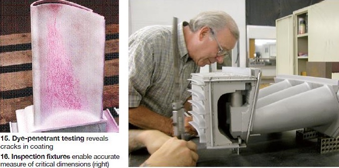
After pre-weld solution heat treatment, NDE should be performed to identify any cracking, wall thinning, and cooling-hole blockage (Fig 15). Dimensional checks define deflection of walls, airfoils, shrouds, z-notches, etc. What follows is a series of thumbnail sketches describing the key actions required during Stage 2 of the repair process to assure accurate verification by the repair vendor of component condition:
Initial visual inspection. Purpose of visual inspection at this stage essentially is to confirm the degradation modes identified during the onsite inspection. Occasionally, however, the better lighting and higher-magnification inspection tools—and more experienced personnel—available in a shop environment reveal damage not observed at the plant. Be sure to document these items with digital photography and investigate further such important findings as coating cracks and rimming, oxidation, corrosion and erosion, and wear.
Mapping of every defect identified in each component and summarizing the information in one drawing could be advantageous for defining the typical wear and damage pattern for that component exposed to that operating condition. Although mapping of defects was common 10 or more years ago, additional inspection charges from the repair facility can be expected for this labor intensive work If the end user’s onsite findings differ significantly from degradation identified in the shop, the plant should consider redefining its inspection procedures to bring them in-line with current industry practice.
Metallurgical evaluation. In most cases, extensive metallurgical evaluation—even destructive testing—is necessary to obtain the information needed to ensure quality, long-lived repairs. Representative metallurgical samples, as well as samples from locations of special concern identified in the preceding visual inspection, are removed for closer examination. Using a microscope, a qualified metallurgist can accurately assess the condition of the base material and internal and external surfaces.
Further definition of the base material, coatings, environmental attack, and other deterioration can be obtained using a scanning electron microscope (SEM) equipped with energy dispersive x-ray microanalysis capability. It is good practice to examine samples, both etched and unetched, at low (50X), medium (500X), and, in the case of gamma prime, at high (10,000X) magnification.
Metallurgical findings should be used to confirm or fine-tune the refurbishment process—for example, to suggest the proper stripping method, the requirement to strip and recoat internal passages, to help identify the optimum coating system for your application, etc. The metallurgist’s report also provides valuable feedback to the end user regarding the level of success of previous repairs and coatings, the identification of manufacturing flaws, and the expected lifetimes of components based on their current condition and anticipated future operating regimes.
Dimensional inspection. The initial, as-received inspection helps identify issues associated with the fit-up of various components—such as those associated with clearances, throat opening, seal grooves, bucket rock, and z-notch contact area. Some of this work relies on the use of fixtures (Fig 16) to replicate the location and position of a given component within the IGT—thereby enabling accurate inspection and measurement of critical dimensions (for example, wall thickness, deflection, tip height). The information gathered helps to identify any special needs that should be addressed during refurbishment. Or, in the extreme, it may suggest that component replacement should be considered.
Beware that some repair facilities forego this inspection to reduce their costs. This means critical dimensional information that might be required for intermediate and final machining, and inspection of the parts, will be lost. Recently developed coordinate measurement equipment and white- or blue-light scanning are replacing conventional inspection methods; although these methods can increase the accuracy and efficiency of the inspection, caution is required to ensure the correct and proper dimensions are measured.
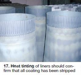 Stripping/cleaning and surface inspection. The stripping plan developed for a given component should consider its base material and coating as well as its condition as determined by metallurgical evaluation. Most of the coating is removed by chemical stripping or grit blasting and lately more and more water blasting is used for combustion parts as well as blades and vanes. Coating material and/or corrosion/oxidation products remaining after this step are removed by hand blending following a heat tint of macro-etch, a procedure that is repeated until the surface is completely clean (Fig 17).
Removal of coatings from components with very thin walls demands special care to ensure that the integrity of the base material is not compromised. Process usually is time-intensive. Be wary of repair facilities that suggest otherwise. Note that it is not always necessary to remove all of the bondcoat on these components. However, success weighs heavily on having a proactive owner/operator available to verify that the coating is removed to the extent required without damaging the base material.
Heat treatments typically are performed in a vacuum furnace; argon and hydrogen furnace atmospheres sometimes are viable alternatives to a vacuum. Heat-up and cool-down rates, as well as time at temperature, are critical parameters for achieving the desired metallurgical and mechanical properties. To ensure quality heat treatment, verify furnace atmosphere, temperature, pressure, etc, with proper monitoring/recording instrumentation. Also, remember to request feedback from follow-on heat-treatment cycles to ensure that the desired metallurgical and mechanical properties were indeed achieved.
NDE alternatives for assessing component condition after pre-weld solution heat treatment include visual, liquid penetrant, ultrasonic, eddy current, and x-ray testing. Depending on component condition, one or more methods is suitable for identifying cracks on or below the material surface, pinpointing cooling-system problems, and measuring wall thickness. Special methods, such as flow and frequency tests, can be helpful in identifying problems such as overheating and high-cycle fatigue.
The owner/operator should compare the repair vendor’s NDE results to its expectations based on visual and dimensional (clearances) inspection at the plant and component operating history. If discrepancies occur, the end user or its representative should review the components, inspection reports, and recommendations, and then meet with the repair vendor. Work should be stopped until after that meeting.
Engineering review of Stage 2 inspection results is necessary to ensure that the existing scope of work for the refurbishment effort is conducive to achieving the desired results. As described in Stage 1, repair work should not proceed until the end user, or its representative, reviews the inspection reports and recommendations and discusses them with the repair vendor.
Don’t be reluctant to make necessary changes to the scope of work at this point in the refurbishment process. However, be sure to factor any commercial and delivery-time consequences into your analysis. Finally, if any changes are made to the scope of work, specifications, and schedule, be sure to update the verification points in the repair process as well as final acceptance terms—if applicable. You’ll sleep better knowing you have done everything possible to ensure reliable operation of your IGT through the next cycle.
Step 5
Verification during the refurbishment process
Step 4 offered guidance for proactive users during the initial inspection process—including metallurgical evaluation, disassembly, cleaning and tripping, post-weld heat treatment, and dimensional and nondestructive examination. That step complete, repairs now can be made where required; also, the components can be recoated. For a snapshot of key steps, refer to the flow chart in Step 2.
Preparation for welding, brazing, coating. Before any of these processes can be performed, the surface must be prepared to ensure that it is free of cracks, coating, oxidation and corrosion products, and other contaminants. For weld repair, cracks generally are removed manually with air tools, followed by PT and visual inspection to ensure that the end of the crack has been reached. Next, the penetrant, developer, oil, and other contaminants are removed to enable proper welding.
Note that that the removal of cracks is a critical task in Step 5 and the temptation for taking “time-saving shortcuts” should be avoided. Be aware, too, that some shops have substituted visual inspection only for stationary components, eliminating PT to reduce cost. This may have quality implications. Premature cracks can develop during pre-weld activities—such as heat treatment—or later during IGT operation when preparation activities are rushed.
A few repair facilities use the same prep processes for brazing as they do for welding. However, most rely on the hydrogen, vacuum, or vacuum/hydrogen partial pressure for cobalt-based materials and fluoride ion cleaning processes for precipitation-hardened nickel-base materials. Their effectiveness on internal surfaces exposed by cracks only can be verified by conducting a metallurgical inspection of a representative sample processed with each batch.
 Surface preparation using grit of controlled quality and size applied at the proper pressure is important. Use of new grit is recommended before coating application; metallic grit before brazing. The time interval between prep and the welding, brazing, or coating stages should be short and the environment controlled to prevent surface contamination. Keep in mind that outsourcing component cleaning to a specialty shop can be in vain unless extreme care is taken to ensure contaminant-free handling, packaging, and transport.
It is particularly important for the end user or its representative to ensure that the contractor adheres to its procedures and scope of work as the first batch of components is repaired, even if that means several visits or a prolonged stay. Items to include on your audit checklist: quality of personnel training, visual inspection of the end results, and the care displayed in handling components to prevent contamination.
Welding. One of your tasks during the repair-facility selection phase was to verify independent qualification of both the welding process and the welders. Components repaired by trained and certified personnel following the parameters outlined in the qualification documentation generally assures that job quality and performance will meet expectations.
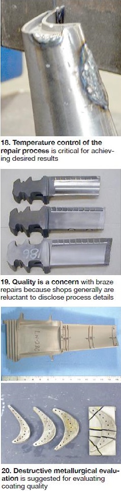
Welding using a low-heat-impact method is recommended to enable a high-quality repair. It minimizes component deformation and the size of the heat-affected zone (HAZ). Time constraints, such as those imposed by lead-time or commercial issues, sometimes suggests the use of a heat input that is higher than desirable. Caution is advised here: It can contribute to deformation or premature cracking at the HAZ (Fig 18).
Even components that can pass the final inspection may be of substandard quality if the welding process is rushed. An unannounced visit during weld repair is suggested to verify the repair facility’s compliance with its procedures, quality specifications, and scope of work. A benefit of having complete confidence in the job being done comes at the end of the project when you might be able to save time by just reviewing the results of the final nondestructive testing rather than by witnessing the PT inspection after post-weld heat treatment.
Brazing raises quality concerns, particularly among end users having no experience with the process or the repair facility recommending it (Fig 19). Reason: Braze compositions and procedures typically are confidential and not disclosed to the customer. But even when disclosed, only limited metallurgical and mechanical data—such as stress rupture, ductility, and impact and crack resistance—are provided. Further, if weld repair is required after brazing it can be challenging.
However, the recent development of brazes containing boron and hafnium, which act as melting-point depressants, have been able to overcome most of the ductility and weld-repair concerns. If your contractor uses braze technology during the repair process (refer to Step 3), demand complete first-article test results. For later lots, verify use of the same procedure that was applied to the first article. Also, that proper inspection steps are in place—including metallurgical evaluation.
Coating. Today, most coatings used in repair processes are applied by robotic thermal spraying. Diffusion coatings find greatest application on internal surfaces. At recent industry meetings addressing thermal spray coatings, the importance of repeatability was emphasized by several presenters. According to the experts, more than 300 parameters can influence the quality of a thermal coating. Thus process repeatability should be a primary focus of your vendor audit. This includes making sure technicians performing the work follow instructions to the letter.
Monitoring of process quality and repeatability includes the following:
-
-
- Verify coating thickness using eddy-current, weight-gain, or physical measurement methods.
- Take bond-strength and metallurgical samples to confirm use of specified procedures.
- Perform a destructive metallurgical evaluation of an actual part (Fig 20) to evaluate coating quality. When this is not possible, verify that specifications for grit cleaning, time between cleaning and coating application, etc, are followed to ensure a quality equal to the quality demonstrated on the first article.
-
Pre-coat inspection. Finally, it is important to verify findings of inspections that cannot be conducted and/or corrected after coating and reassembly—such as area and check, harmonics, and wall thickness. The repair facility should provide these results to the end user or its representative for review.
Step 6
Verifying final inspection
The last step of any final-inspection verification should be a review of all quality records for conformance to specifications. Things to remember:
-
-
- Ensure that all records are signed by the appropriate technician, inspector, or engineer, and dated.
- Be sure documentation includes certificates for materials and specifics of all subcontracted processes.
- Verify traceability of materials—including weld filler and braze—to their certs.
- Confirm proper heat treatment based on recorded temperatures, time on temperature, heating and cooling rates, and quality of atmosphere.
- Check coating certifications, including metallurgical evaluations, and inspection documents—NDE, dimensional, flow, frequency, area, and harmonics, as well as moment-weight and sequence charts.
-
Some of the quality records may reveal items out of spec or identify other concerns that should be addressed during final verification. Keep copies of critical records for your files.
NDE verification. Confirm the condition of your components as soon as practicable after final heat treatment. Inspection at this stage gives a good indication of workmanship and overall condition of your components. However, keep in mind that the new coating can limit the effectiveness of liquid-penetrant testing and mask cracking that could occur during heat treatment. PT and/or other NDE methods should be conducted after each heat treatment, but especially after the last one. Verify the quality of any touch-up work with PT and retain documentation.
Consider being present in person or through a representative during all final NDEs—or at least until good insight is obtained regarding practices in use at the repair facility during days, nights, and weekends. Keep an open mind regarding blend repairs versus weld repair if inspection results suggest rework: It’s the quality of the repair that’s important, not its appearance.
Dimensional verification of critical measurements—including roundness, clearances, height, thickness, throat openings, etc—provided by the repair facility is strongly recommended. The validity of these measurements depends in large part on the dimensional accuracy of fixtures used as part of the repair process. Recall that fixture qualification was conducted as part of Step 4. True verification of dimensional accuracy comes when components are reassembled into the GT. Feedback from this work should be incorporated into your final report and factored into future decisions regarding vendor selection.
If specifications agreed upon with the repair facility are not achieved, for future projects you may want to consider making performance requirements less demanding and/or changing the scope of work. Alternatively, you might consider a new vendor.
Other. Depending on the component, other measurements may be needed to confirm the quality of work done—including cooling-air flow, frequency, moment weight, area, and harmonic checks. Well-defined specifications should be developed for these operations because industry standards typically are not available. Suggestion: Let the repair facility repeat some of the measurements required to be sure it can achieve an acceptable level of repeatability and that all measurements are within spec.
This information may be of greater value in the future when experience indicates what components are most susceptible to failure and when working with advanced components. Later review of quality records—such as heat-treatment charts—also may warrant a closer look at some of the repair and inspection processes used and possible changes to those processes. The value of lessons learned is that they can be incorporated into future repair work to improve quality.
The final visual. Before your components are loaded for shipment, conduct a final visual inspection to ensure that the parts are clean and not susceptible to handling damage. This is especially important for the fragile coating edges. Also, be award that the coating and the last grit cleaning operation can close up cooling holes. They should be inspected using wire, light, water, and/or air methods. Finally, be sure that shipping containers are sturdy enough to withstand the rigors of transport and that your components are well supported in these containers.
Acronyms defined
APS—Air plasma spraying
AR—As received
CNC—Computer numeric control
CVD—Chemical vapor deposition
DSD—Downstream deflection
EDM—Electrical discharge machining
GT—Gas turbine
EB—Electron beam
HAZ—Heat-affected zone
HIP—Hot isostatic pressure
HVOF—High-velocity oxygen fuel
IGT—Industrial gas turbine
ISO—International Organization for Standardization
LPPS—Low-pressure plasma spraying
LTSA—Long-term service agreement
MCrAlY—Nickel, cobalt, iron, or a combination of these elements, plus chromium, aluminum, and yttrium
NDE—Nondestructive examination
ET—Eddy current test
PT—Liquid penetrant test, also called LPT
MT—Magnetic particle test
RT—Radiographic test
UT—Ultrasonic test
VT—Visual test
Nadcap (see footnote)
OEM—Original equipment manufacturer
RCA—Root-cause analysis
SEM—Scanning electron microscope
TIG—Tungsten inert gas (same as GMAW)
VPS—Vacuum plasma spraying
———————————————————————–
NADCAP began as an acronym for National Aerospace and Defense Contractors Accreditation Program. Today that program is international in scope and known simply as Nadcap. The Performance Review Institute, Warrendale, Pa, administers the program, which “provides unbiased, independent manufacturing process and product assessments and certification services for the purpose of adding value, reducing total cost, and facilitating relationships between primes and suppliers.”
Hans van Esch (hvanesch@teservices.us, 281-867-1500) has more than three decades of experience in the development of repairs and coatings for industry leaders—including Sulzer Elbar, Hickham, and Chromalloy. He founded TE-Services to support plant owners and operators with training, component and metallurgical evaluations, repair and bid specifications, third-party inspection and audits, etc. Over the years, other experts in component repairs and rotor inspections—such as Shaheen Hayatghaibi and Mike Beauchamp— have joined the company, increasing its experience base and service offerings.