


By Donald Selkirk, PE, SaskPower
According to IEEE Standard 100, partial discharge (PD), is “An electric discharge which only partially bridges the insulation between conductors, and which may or may not occur adjacent to a conductor.” IEEE 100 goes on to say “Partial discharges occur when the local electric-field intensity exceeds the dielectric strength of the dielectric involved, resulting in local ionization and breakdown.”
In simpler terms, PD is an electrical discharge or spark that occurs within a high-voltage insulation system. The discharge bridges only part of the gap between two energized surfaces, or an energized surface and ground, thus it is only a partial discharge.
While lightning is not a form of PD, comparing the two phenomena can shed some light on PD. For a lightning strike to occur, there has to be a voltage differential between the clouds and the earth large enough to breakdown the dielectric—in this case, the air between the clouds and the earth. When the voltage becomes large enough, it ionizes the air, forcing the air molecules to release electrons. These electrons then move, en masse, in the direction dictated by the voltage. This net movement of negatively charged electrons is, by definition, a current flow, which is seen as a lightning strike.
The lightning metaphor breaks down in one respect; a lightning strike is not a partial discharge because it completely bridges the gap between the two conductors (the clouds and the ground). In order to restore the value of the lightning example and make it more like PD, imagine these two things:
- The cloud-to-ground voltage never gets high enough to ionize normal air. In this manner our normal air becomes like the generator’s insulation system.
- There is a small bubble of unusual air in the atmosphere that is more easily ionized than normal air and therefore has a lower dielectric strength than the normal air. This bubble is like a flaw in a generator’s insulation system. Then imagine that if a significant voltage were applied to the unusual bubble of air, you might get a small lightning bolt within the bubble. This is a partial discharge.
How does PD occur in a stator winding?
In a generator stator winding, voids occur when there is a small air pocket within the insulation system. The dielectric strength of solid insulation can be as much as 100 times greater than air. As one would expect, manufacturers of electric machinery and equipment go to great lengths to avoid this problem.
Unfortunately there is no such thing as a perfect insulation system. Air pockets can result from defects in the manufacturing process, mechanical damage to the insulation (often caused during bar installation), contamination, insulation system delamination, and ageing. PD activity in insulation voids often occurs within the slot portion of the stator winding, because the energized copper conductor is very close to the grounded stator core. This type of PD is commonly referred to as “slot PD.”
PD activity also can occur in other locations, like in the end winding, where bars of significantly different voltages are too close together. Another common PD location is at the exit of the stator-core slots, if voltage grading is not properly applied.
What’s the difference between PD and corona?
In the industry, the terms PD and corona are commonly used interchangeably; however, this is not correct. Both corona and PD are electrical discharges that occur in high-voltage equipment when the strength of the applied electric field is great enough to cause ionization. But the IEEE Standards define corona as “A luminous discharge due to ionization of the air surrounding a conductor caused by a voltage gradient exceeding a certain critical value.”
PD is not necessarily luminous or visible. Further, PD may not occur adjacent to an energized conductor and need not occur in air or gas. Additionally, a corona discharge may bridge the entire gap between energized conductors; PD is a localized phenomenon.
What is the difference between PD and vibration sparking?
The term “spark erosion” (SE) must be used with caution: Most often it refers strictly to vibration sparking; occasionally to both vibration sparking and PD. This article uses SE to refer to vibration sparking.
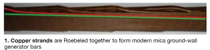
Before proceeding with an analysis of vibration sparking, some background information is in order. When modern mica ground-wall generator bars are constructed, copper strands are Roebeled together to form the bar (Fig 1). Note that Roebel transposition is a process for making stator bars in which the individual conductors that make up the bar are twisted together such that each individual conductor occupies every position within the bar at least once. This is done to reduce circulating currents within the bar.
The bar usually is wound with a layer of semi-conductive tape to provide inner corona protection. Mica-based, ground-wall tape then is applied. This tape creates a wall between the energized bar copper and the grounded stator core and frame. A second layer of semi-conductive tape is applied on top of the ground wall to provide outer corona protection.
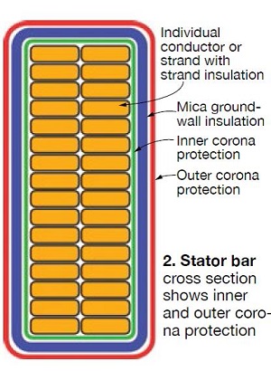 In the end region of the bar, near the slot exit, a voltage grading tape is applied in order to reduce the electrical-stress gradient at the end of the slot grounding tape in the end winding near the slot exit (Fig 2). The outer corona protection provides a path to ground for any charge that builds up on the surface of the bar and thus, by design, current flows through this layer from the surface of the bar into the stator core.
Vibration sparking occurs when the current in the outer corona protection layer, flowing into the stator core, is interrupted because movement of the stator bar open-circuits the current path. This phenomenon is similar to the sparking that occurs when an electrical contact that is carrying current opens.
Vibration sparking only can occur when the stator bars are vibrating, such that there is relative movement between the stator bars and the stator core. Further, stator-bar vibration also can abrade the ground wall to the extent that a ground fault occurs. Given that the resistance of the outer corona protection is not less than 300 to 2000 ohms per square, the sparking damage should be prevented.
Damage caused by PD versus vibration sparking
Generally speaking, PD deterioration of mica-based ground-wall insulation in the slot is a very slow process. Even a stator winding suffering from severe PD may last many decades before a rewind is necessary (provided that ozone levels are not beyond acceptable limits).
Vibration sparking is much more serious and has been known to cause winding failure in as little as three years. But, if the stator bars are kept tight in the slots, vibration sparking cannot occur.
If a generator is suffering from severe PD—to the extent the packing material that keeps the bar tight in the slot deteriorates—bar vibration could begin. PD also deteriorates the outer corona protection, which causes an increase in its resistance, which would resist the flow of current and, one might assume, reduce the severity of sparking. However, this has not been the case. Industry experience shows that PD and vibration sparking seem to grow together. In any case, it is best to ensure that a machine suffering from PD is kept securely wedged so that bar vibration cannot begin.
How to detect PD and vibration sparking
When diagnosing vibration sparking versus PD, it can be difficult to ascertain whether one phenomenon, or the other, or both are taking place. It should be noted that PD can only occur on the high-voltage bars in the winding, but vibration sparking can take place at any voltage, including neutral.
There are several ways to detect PD. They can be broken down into two primary groups: online and offline detection. Online PD detection is done either by using a radio-frequency current transformer (RFCT) to measure electromagnetic interference (EMI) or by measuring and analyzing the PD voltage pulses (referred to as PD detection). Both systems have been in use for decades.
Electromagnetic Interference Method. EMI is generated as a byproduct of energy conversion from power frequency to radio frequencies at the site of an electrical defect. EMI data are collected by applying an RFCT to the generator-neutral lead or to the generator-frame ground.
EMI monitoring can provide information on PD within a stator winding as well as condition-based information on the stator, rotor, bearings, oil seals, exciter, bus, and associated electrical systems. Potential drawbacks to EMI monitoring with an RFCT are that specialists are required to perform the data collection and analysis. Also the equipment is installed temporarily, so long-term data logging is not possible.
PD Detection Method. Online PD detection via pulse measurement is done by installing capacitive coupling devices in or near the generator. These devices filter pulses into PD monitoring equipment. PD detection is concerned with these four characteristics:
- Magnitude, which relates to the size of the insulation voids.
- Pulse count, which relates to the number of insulation voids
- Polarity, which relates to the location of the voids within the insulation system.
- Position relative to the phase-to-ground voltage, which relates to whether the PD activity is driven by phase-to-ground or phase-to-phase voltage.
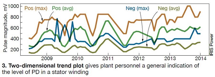
PD detection can provide simple, two-dimensional PD monitoring and data logging accessible to plant personnel, or three-dimensional PD monitoring done by trained technicians using specialized equipment. The former delivers PD pulse-height analysis plots, which provide plant personnel with a general indication of the level of PD in the stator winding and data trending that indicates whether any changes have taken place in the amount of PD in the winding (Fig 3).
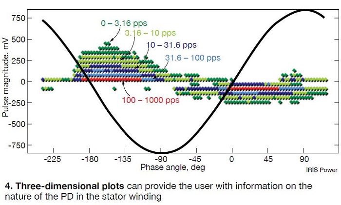
Three-dimensional PD monitoring delivers pulse-height analysis plots and phase-resolved plots of stator winding PD activity and can provide the user with a great deal of information about the nature of the PD in the stator winding (Fig 4). It also can provide information on the location of the PD (slot, end winding), relative size of the worst insulation defects, quantity of insulation defects, and whether the PD may be related to vibration sparking.
The advantages of PD monitoring are that a permanent installation provides continuous two-dimensional data logging and the ability to do more in-depth, three-dimensional data logging without taking the unit out of service. In addition, PD analyses via voltage pulse measurements have a longer track record in the industry. The disadvantages include the need to take equipment offline to install and calibrate the system and not having the ability to monitor other conditions.
Whether using EMI detection or the traditional PD voltage pulse monitoring, online monitoring provides only an indication of the health of the insulation system—not an absolute measurement of remaining life. Further, the most valuable PD data are historical data for the machine of interest. Therefore, it is best to start PD monitoring programs early to have good data available for comparison purposes. Offline testing and visual inspections are strongly recommended when online testing indicates a developing problem.
Ozone resulting from PD
Ozone is created by electrical discharges in air. It exists naturally in the upper atmosphere, where it helps block harmful UV radiation from the sun. Low levels of ozone also exist naturally at ground level, in concentrations of 0.020 to 0.035 ppm.
Ozone is created by PD in generators, too. This is a problem because it is dangerous to humans even at low concentrations. And, levels of ozone in powerplants can be quite high (sidebar). In one case, ozone production at a 225-MW powerplant was so high that a blue haze could be seen in the generator room. Measurements taken inside the generator enclosure showed steady-state concentrations of 40 ppm of ozone—400 times the OHSA limit for an eight-hour time-weighted average.
To solve the immediate problem, air in the enclosure was circulated through a carbon filter, which reduced the level to 2 ppm. A visual inspection of the machine showed widespread deterioration of the slot’s outer corona protection and substantial corrosion of ferrous parts and rubber components, confirming significant levels of PD.
Since research has shown that ozone levels directly correspond to PD levels, testing for ozone is a good indicator of PD, but it must be done properly. Review the path of the cooling air and accessibility when determining locations for measurement. The objective is to take air samples as close as possible to the source of discharge.
Ozone exposure
OSHA regulates ozone in the workplace based on the following time-weighted averages:
- 0.2 ppm for no more than two hours exposure.
- 0.1 ppm for eight hours per day of exposure doing light work.
- 0.08 ppm for eight hours per day of exposure doing moderate work.
- 0.05 ppm for eight hours per day of exposure doing heavy work.
Ozone at ground level can decrease lung function, aggravate asthma, cause throat irritation and coughing, chest pain and shortness of breath, inflammation of the lung tissue, and higher susceptibility to respiratory infection. Ground-level ozone is one of the five major air pollutants that the EPA uses to calculate the Air Quality Index.
Ozone levels of 0.020 to 0.035 ppm, the range of normal ground-level concentrations, indicate no PD. Levels of 0.030 to 0.040 ppm would be considered moderate; 0.060 to 0.090 ppm, high. As is the case with online PD monitoring, being able to compare ozone levels over time is the most valuable approach, so it is best to start ozone monitoring programs early.
Long-term effects of PD
Besides the production of ozone, the long-term effects of PD include the (1) possibility that it may morph into vibration sparking and (2) continued decay of the outer corona protection in the slot and in portions on the end winding.
As discussed above, vibration sparking is a dangerous condition that can abrade the ground-wall insulation and cause a ground fault between the stator core and the energized stator bar. Typically, utility generators are high-resistance-grounded, meaning that a current-limiting resistor is installed between the generator neutral and ground. This circuit will limit current to the range of 3 to 10 amps. In the case of a single line-to-ground fault (SLG), the current path for the fault current is from the stator bar, into the stator core to ground, through the neutral-grounding resistor (NGR), back through the winding, and to the source of the fault.
The presence of the resistor limits current to a very low value, so damage to the stator core is highly unlikely. If the voltage across the NGR is high enough, ground-fault protection will operate and trip the prime-mover fuel supply and generator excitation. The greater worry is the possibility of a second ground fault occurring before the protection operates.
If vibration sparking is widespread throughout the machine, then much of the ground-wall insulation may have deteriorated. When the first ground fault occurs, current flow through the NGR causes a voltage drop across the NGR. This, in turn, causes the neutral voltage to rise from zero to the line-to-ground voltage.
The increase in neutral voltage elevates the phase voltages from line-to-ground to line-to-line values. The deteriorated ground-wall insulation is now exposed to a higher voltage and is very likely to experience a second failure. Further, because the common ground-fault protection reacts to the voltage across the NGR (or in some cases, current flow through the NGR), it will not react to a ground fault very near the neutral; the fault does not create enough voltage across the NGR to cause the protection to operate. So, there may already be an existing ground fault.
If two ground faults occur almost simultaneously, either because one fault already existed or because the elevated voltage punctures another weak location in the insulation, there is now a double line-to-ground fault (DLG). In the case of a DLG fault, the presence of two faults short circuits the NGR and the current flow through the fault is limited only by the resistance of the faults and the stator core. This resistance is typically very low and can easily result in tens of thousands of amps of current flow. Result: Substantial damage to the stator winding and core, which will almost certainly result in the need to rewind the machine and restack the core. The rotor may be affected as well.
At minimum, generator owners should confirm correct settings and operation of existing ground-fault protection and may also wish to consider the addition of a ground-fault protection scheme that provides 100% winding protection.
Unfortunately there is very little that can be done to eliminate PD in the stator slots short of a rewind. Options that often are considered are the injection of conductive silicon to restore the outer corona protection and reversal of the generator neutral and high-voltage terminals. Injection of conductive silicon is often rejected because it is very difficult to remove should a future rewind be necessary. Also, increased heating is likely to occur because the silicon can block the ventilation ducts in the stator core.
It is possible that if PD is occurring only in a few localized areas, and those areas can be located by testing (ozone, corona probe, lights-out test), that a local injection of conductive silicon would both eliminate the PD and not cause the problems associated with widespread silicon injection.
Reversal of the high-voltage and neutral ends of the machine is another option, but involves reconfiguring the high-voltage and neutral terminals. The advantage is that the high-voltage bars, where PD has damaged the semiconductor, become the low-voltage bars, where PD doesn’t occur. Therefore, the low-voltage bars, undamaged by PD, become the high-voltage bars. This solution is commonly considered but rarely implemented because of the cost and complexity of reconfiguring the generator.
Corona in the end windings often can be cleaned up and repaired by painting on new outer corona protection. In many cases these repairs result in a reduction in PD level when the machine is returned to service. But when the repairs no longer result in a PD reduction, it may mean that slot PD has become the dominant source. CCJ