Don’t underestimate the value of coffee breaks at user-group meetings. The informal chatter and cross-talk at these gatherings is almost certain to uncover information of value. Example: At the first break during last May’s 7F conference in Atlanta, the editors learned of a Technical Information Letter (TIL) concerning collector flashovers that had been issued by the market leader only two months earlier.
The gas turbine (GT) gets the lion’s share of attention at user gatherings, and editors always have their antennae out to identify other topics of interest to owner/operators. You can write just so much about the basic engine. A couple of delegates told the editors that TIL 1631 was issued to assure that users were aware of the positive impact proper collector maintenance can have on generator reliability.
New topics are most welcome, but they usually require some digging to learn enough about the component/system to ask the appropriate questions regarding the nature of the problem, how it impacts O&M, and how to avoid it in the future. Caught unawares, the editors asked, “What collector, where?” “Generator exciter” was the reply. Next step: Do a quick Internet search and then sit down with a couple of users over lunch for a crash course.
 Excitation current is supplied to 7F generators via a collector system consisting of slip (collector) rings, brushes, brush holders, and connections to the field winding. Dc flows from the exciter, through the negative brush and slip ring, to the rotor field poles. The return path to the exciter is through the positive brush and slip ring.Background. Recall that a generator requires direct current (dc) to energize its magnetic field. The exciter’s job is to supply this current. Alternating-current generators may have rotating (brush or brushless) or static-type exciters. Large gas and steam turbines, like the 7F, generally have a static exciter.
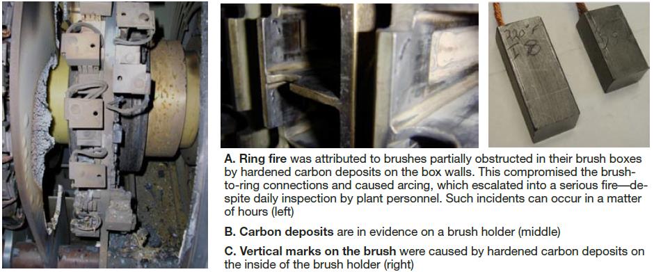
Collector rings for 7Fs are heat-treated steel forgings shrunk over insulated steel hubs. Carbon brushes transfer current to the spinning slip rings. Preserving the intimate connection between the brush and slip rings is critical to preventing ring fires, which can damage the collector system. The first sign of an impending problem is arcing caused by a progressive loss of contact between the ring and one or more brushes.
One of the challenges facing many plant managers at gas-turbine-based generating facilities is that staff size and experience militate against checking all equipment to the degree they would like and as frequently as they would like. Plus, exciters are a special case. Reasons: Arcing sometimes is difficult to identify. Plus, O&M personnel often are reluctant to get close to a piece of equipment that can be intimidating for its electrical shock potential.
Serendipity. In one day the editors learned of a problem they didn’t know existed (morning), received a background education (afternoon), learned that a solutions provider would be attending the vendor fair (also afternoon), and got to speak with representatives of Cutsforth Products Inc, Cohasset, Minn (evening). This could only happen at a user-group meeting. Everything should be this easy.
First thing an editor tries to do when making a “cold” stop at a vendor’s booth is to “qualify” the person he or she is talking to. Is that person truly an expert on the subject of interest or just a knowledgeable sales man or woman? In this case, the experts were on hand.
Next, a leading question: “Why would an OEM alert its customers to the need for proper collector maintenance? Sounds so mundane, and the topic rarely, if ever, is addressed at user meetings.” Fig A is the only answer necessary.
Collector-ring issues. The answer to the next question—“What causes an incident like this to occur?—takes some time. One place to start is with collector-ring issues—including going out of round, grooving, and so-called photographing (also called ghosting or foot-printing).
- Two reasons rings go out of round: (1) Problems with brushes and brush holders compromise the brush-to-ring connection, which is conducive to electrical erosion. (2) Contaminated air results in mechanical wear, which causes brushes to lift off the ring. Unit vibration is associated with most out-of-round conditions.
 Grooving occurs when the brush has poor contact with the ring. Typically, current passes through an arc, eroding away and grooving the ring. But grooving can be caused by contaminated air as well.
- Photographing is identified by a brush-like image in the surface of the ring. It often is traced to problems with the brush holders.
Truing of the slip rings under load is the way to deal with out of roundness and ring blemishes. But this takes time and costs money.
Brush gear. The conversation shifted to brush gear. “The brush often is blamed for collector-ring wear,” the Cutsforth experts said, “but the root cause typically is the brush holder. Almost always, too little brush contact pressure is the specific problem, which is influenced by the brush holder and/or the spring. The brush holder contributes to insufficient contact pressure by restricting free movement of the brush.”
The buildup of small mounds of carbon inside the brush holder is one cause of brush hang-up (Fig B). Carbon particles are produced by the repetitive impacting of the brush against the holder wall (Fig C). Such buildup is difficult for maintenance personnel to see but it can be identified from marks made in the side of the brush.
Brush binding is another cause of holder-related restriction (Fig D). It is caused by the brush dragging against the side of the holder. Angular pressure increases the likelihood that the brush will become stuck in its holder. Where the brush box is shorter than the brush it holds a ledge can develop in the brush and cause it to hang-up.
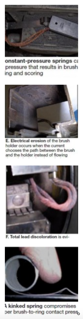
Surface roughness of a brush holder is yet another impediment to free brush movement (Fig E). This problem occurs when current passes through the side of the brush holder because of a poor terminal connection, poor shunt-wire connection, or the brush is too long.
Lead discoloration at the terminal end is an indication of a poor terminal connection. But when the full length of the brush shows extreme heating, you are looking at the results of so-called selective action. In Fig F, the brush with the discolored lead was the brush with the best connection to the system.
Spring problems. Worn, damaged (Fig G), or broken springs lose some or all of their tension and cause brush wear and out-of-round rings. Too much spring tension can increase brush wear but not mechanical wear of the ring. The Cutsforth people pointed out that most springs are attached to the back plate of the brush holder and cannot be changed without a shutdown.
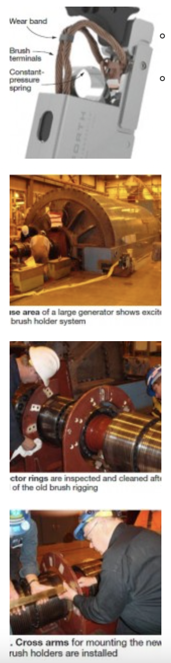
The solution. Dave Cutsforth, the firm’s president, told the editors in a follow-up phone call that years of personal experience went into developing the EASYchange® brush holder system (Fig H). It assures safe removal of the brush and brush box as a unit within seconds—while the generator is operating. This allows inspection 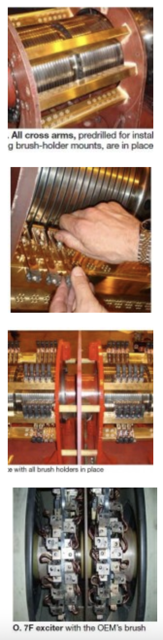 and maintenance away from the exciter in a comfortable environment.
When the brush is changed, the spring and spring portion of the terminal connector are replaced as well. The spring clips into the brush box in the Cutsforth design, facilitating its replacement. Note that by changing spring and brush at the same, spring tension is maintained to be constant over the life of the brush, minimizing the potential for abnormal spring-tension-related collector-ring wear. The terminal connection automatically engages when you close the handle. Finally, brush wear is easy to gauge with the holder in place by checking the distance from the wear band to the brush box.
Application. Most applications only require one standard-size EASYchange brush holder; it serves all generators, minimizing the need for multiple models and spares. The effort required for retrofitting generators depends on the machine. Perhaps the most involved is a replacement of the type profiled in Figs I through N for a large steam turbine.
The doghouse area is exposed showing the exciter on a stub shaft at the end of the generator (Fig I). The collector rings in Fig J are easy to inspect with the old brush rigging removed. The positive and negative rings are separated from each other by the insulated frame in the center of the shaft.
Cross arms for mounting the new brush holders are installed in Fig K with this portion of the job complete in Fig L. The holes in the cross arms are precisely drilled for installing the brush-holder mounts (Fig M) and retaining the brush holder in proper position.
The brush holders slide over the mounts and are locked in place by positioning the handle at about a 45-deg angle as shown in Fig N.
Most gas turbines, including the 7F, are easier to retrofit: A simple adaptor allows quick installation of the brush holders. Figs O and P are before/after photos for a 7F replacement.
The company reps said a 7F retrofit takes less than a day and that a turnkey install for this machine is less than $50,000. If justification is done on a life-cycle cost basis, the added safety and reliability, and promise of lower maintenance costs, are expected to repay the initial investment several times over. Several hundred retrofits have been done since EASYchange was introduced about six years ago. One eastern utility alone has replaced the brush system supplied with more than three dozen of its 7FAs.