

With a little luck, you’ll never experience significant rub damage to your rotors. By design, OEMs usually provide generous clearance between the rotor and non-rotating parts except where it’s unavoidable: bearings and seals. OEMs mitigate the rubbing risks associated for those close clearance components with smart material selection—such as Babbitt, brass, and nylon. Those features work well enough when everything operates according to design, but that doesn’t always happen.
When significant rub damage does occur, say Calpine Corp’s Craig Spencer and GenMet LLC’s Neil Kilpatrick, repair options can be limited based on location and severity, but ideally the remedy requires only removal of the heat-affected material, which can be tricky if not done with the proper process.
Shaft rub basics. When your rotor is turning, any solid material that comes into contact with the rotor surfaces has the ability to cause rub damage. The severity of that damage depends on the total amount of energy and rate of energy transfer which occurs during the rub.
The most common rub occurs when some hard substance (grit) gets caught between the rotor and the bearing or the seals and that grit exceeds the given clearance, causing the grit to machine the surface of the rotor, making a groove with no evidence of heat, metal adhesion, or bulging.
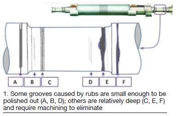
Normally, a few small grooves pose no appreciable risk, and can simply be polished out (Fig 1; A, B, D).
If there are more than a few grooves, and/or if they are relatively deep grooves—such as from a hydrogen seal (Fig 1; C), bearing oil seal (E), or labyrinth seal (F), you may need to perform a step machining of the shaft surface, and replace the seals, and possibly the bearing, to fit to the new diameter.
Another common rub occurs when seal strips are set to an inadequate clearance during a maintenance outage. Generally speaking, these seal strips will wear in the necessary clearance in time, sometimes yielding deposits from the seal strips adhered to the shaft. Usually there’s no appreciable damage to the shaft substrate, and only shaft polishing is needed to remove the deposits. However, severe cases should be metallically evaluated after polishing, as noted with friction rubbing described below.
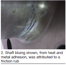 Less common, but potentially much more severe, is a friction rub created by contact between the turning rotor and a non-rotating member of the unit assembly as a result of an abnormal operating condition—such as a loss of lubrication or an abrupt lateral event like an L-0 blade liberation. Because of the relatively high energy transmission in a relatively short amount of time, these friction rubs often do show evidence of heat, metal adhesion, or bulging at the rub site. Fig 2 shows an example of shaft bluing from heat and metal adhesion attributed a friction rub.
Possible remedial options for friction rubs include, in order of severity:
-
- Machining out the damage to a smooth bottom groove.
- Machining the damaged zone smooth and locally heat treating to temper back the heat-affected material.
- Machining out the damage and replacing the removed material using TIG welding.
- Replacing the shaft in whole or in part.
To better understand the need for these repairs, we should better define the physics of this type of damage.
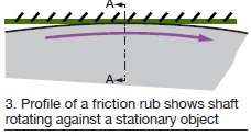 Friction rub physics. The profile of a friction rub is depicted in Fig 3, where the rotor (in gray) rotates against a stationary object.
Because of the great momentum in the rotating shaft, it usually will continue to rotate no matter how hard it makes contact with the stationary object, at least for some time. High-energy friction contact can result in highly localized extreme temperatures within the shaft in proximity to the rub, often exceeding 1300F. Given that shafts normally are made of high-strength, low-alloy steel, this heating is often enough to locally transform the structure to soft austenite.
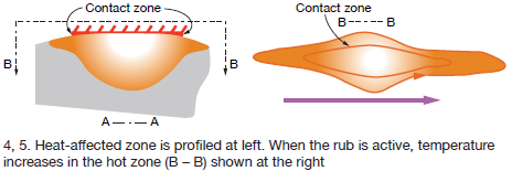
While the rub is active, heat flows into the rotor as depicted in Figs 4 and 5. As temperature builds in the hot zone (B-B), the hot metal tries to expand, but the cold surrounding metal is much stronger and more stable and compressional yielding occurs. As temperature increases, compressional yielding increases and locally reduces the strength.
During this intense rubbing, it’s common to form adhesive metal-smearing deposits on the surface.
When rubbing stops, the hot zone effectively is quenched down to the temperature of the surrounding metal. In typical rotor magnetic-steel components, this means that a local hardening transformation to martensite can occur. At the same time, a significant contraction of the former hot zone occurs, and the stress state of transformed metal zone will change to what can be a very high tensile stress.
Martensite is very hard and brittle, and so it is not uncommon for cracks to develop at this point because of the residual tensile stress. Rub severity is somewhat proportional to the likelihood for cracking to occur.
With this type of damage, crack initiation and propagation from normal operating stresses cannot be predicted, but, clearly, the probability of cracking is likely significant. This condition also means that the part (rotor forging, blower hub, blower blade, etc) is now capable of erratic and unpredictable behavior. This makes it imperative to treat or otherwise remove the damaged material, collectively known as the heat-affected zone (HAZ) from the shaft if it is to remain in service.
HAZ removal. As noted above, there are several repair options, depending on the location and severity of a shaft rub.
Usually, the most cost-effective and expedient manner to deal with a HAZ on a shaft involves machining it off. Because you want to preserve as much of the shaft substrate as possible to endure operational stresses, this machining is an iterative process, where usually skim cuts of the surface on the order of a radial depth of 5 to 25 mils are taken, and the remaining surface is evaluated for a need for additional skim cuts.
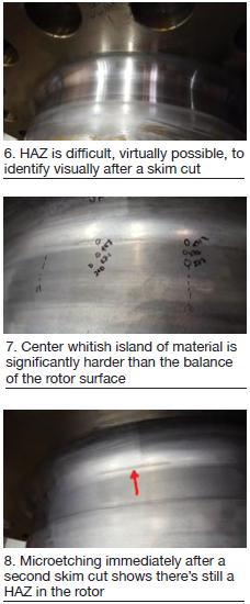
Depending on method of evaluation, there are challenges to accurately determining the remaining HAZ after a skim cut. If you look at Fig 2 of the as-found rotor, the damaged area is obvious. However, as you can see in Fig 6, the HAZ is much more difficult, if not impossible, to identify visually after a skim cut. The entire surface looks the same.
 Within the HAZ, changes have occurred in the microstructure of the rotor steel. As a result, the steel in the HAZ is harder. Given that it’s not practical to cut up the shaft to examine the microstructure under a microscope to check for HAZ, it is common practice to check the hardness of the shaft as a proxy for determining if HAZ remains.
Typical hardness testers use a pen-like device to shoot a diamond-tipped projectile into the shaft surface and measure its response. It tests one location at a time with each impact. The reading is a highly localized average of the hardness at the test location.
And there’s the figurative rub: How can you be certain that you’re testing the correct location with this highly localized test on a rotor surface which looks like Fig 6? After a skim cut, it’s too easy to lose your references for locating the potential remaining HAZ, meaning you may get a false negative report showing no remaining HAZ simply because it was tested in the wrong location. This opens the door to possible crack initiation in service due to the remaining hard material.
A better alternative to evaluating remaining HAZ is a process called macroetching. It involves first polishing the surface with about a 600 grit or finer sander, and then applying an acid solution to the surface (10% Nital in this case). The changes in the steel microstructure cause variations in the grain structure and precipitates around the grain boundaries. The macroetching solution helps to accentuate these grain boundaries in a way which can be visually discerned with the naked eye in localized regions on the shaft.
In Fig 7, you can see the results of macroetching after the first skim cut, as well as measurements of Brinell hardness (HB). The hardness in the primary macroetching indication measured 457 HB, while measurements outside of the HAZ measure a nominal 271 HB. If you’ve got really sharp eyes, you may be able to discern in Fig 7 how there is a center whitish island of material surrounded by a material which is darker than the balance of the rotor surface. Such an appearance is typical of significantly hardened material.
Unfortunately, the rotor surface in Fig 7 is somewhat mottled by contact after the etch was performed. For a better perspective of what a rotor surface looks like shortly after macroetching, refer to Fig 8, which was captured after the second skim cut. There’s no need to do a hardness check because it’s obvious that there’s still a HAZ in the rotor.
Conclusion. Rather than hardness testing, you should insist on macroetching to evaluate remaining HAZ when dealing with magnetic steel. Don’t assume that the shop uses macroetching as a standard practice. Even if the shop isn’t familiar with macroetching, they should have a metallurgist/NDE contact who is. But in every case, the work must be done by qualified personnel.
Stainless steels are more difficult to examine with macroetching, so if your rub involves a stainless component, like a generator rotor endwinding retaining ring, it is even more important to consult with an expert metallurgist for options.


