


Sponsored content – Chevron
Chevron VARTECH industrial cleaner helps restore gas turbine to maximum power
Chevron’s San Joaquin Valley Business Unit (SJV) operates more than 16,000 wells in the Kern County area of California, where summertime temperatures frequently are in the triple digits. Yet the state’s top oil and gas producer has thrived in this severe environment for more than a century, today producing 159,000 barrels of crude and 53 million cubic feet of natural gas daily.
In an oilfield located in McKittrick, west of Bakersfield, SJV operates a Solar Taurus 60 gas turbine in a cogeneration configuration—simultaneously producing steam and electricity. The steam facilitates the recovery of heavy crude oil; electricity is sold to the local utility.
Chevron is recognized for its world-class expertise in oil recovery by way of steam-flooding—a method in which saturated steam is injected into the oil reservoir to reduce crude viscosity and assist in pumping it to the surface.
During last summer, the gas turbine was running too hot to operate at its full design capacity of 5.5 MW. Even when operating just below the lube-oil and bearing alarm temperatures, the turbine could produce only 3.3 MW, causing an annual revenue shortfall of about $350,000, in round numbers.
While high ambient temperatures might be a contributor to the problem, the SJV operations team also suspected that varnish could be insulating heat-transfer surfaces and reducing oil-cooler efficiency. Visual inspection of the lube-oil reservoir revealed varnish bathtub rings, supporting the suspicion that varnish was the culprit.
To address the varnish issue, the SJV team did the following:
Changed the oil filters.
Replaced 15% of the used in-service oil with Chevron VARTECH™ Industrial System Cleaner (ISC).
Restarted the system.
As the gas turbine approached full capacity, it was apparent that something had changed radically: All system temperatures remained within the acceptable range and no alarms were triggered. Specifically, the lube-oil header temperature dropped to 154F from 159F after the addition of VARTECH ISC, while the bearing temperature went from 206F to 194F. Perhaps more importantly, unit output increased from 3.3 MW to 5.5 MW.
The gas turbine continued to operate at full capacity for two weeks with no high-temperature alarms. Then the mixture of used in-service turbine oil and VARTECH ISC was drained. The system was flushed, filters replaced, and the system refilled with Chevron GST® turbine oil.
Andrew Gerlings, lead power solutions operations engineer, noted that “VARTECH Industrial System Cleaner did its job perfectly, and we can now run the unit at its full design capacity. The operators are very happy because they don’t have to constantly monitor temperatures and juggle the output.”
The bottom line: VARTECH ISC allows SJV to operate its cogeneration system at full capacity year-round, even during the hottest summer days, to ensure maximum revenue from the sale of electricity.
To learn more about Chevron’s premium lubricants and targeted programs for powerplant applications, please visit www.chevronlubricants.com.
Steam Turbine Users Group 2020
The 2021 conference of the Steam Turbine Users Group (STUG) will be an in-person event at the Marriott St. Louis Grand, August 23-27, and co-located with the annual conferences for the 7F, 7EA, and Power Plant Controls user organizations—all organized and managed under the Power Users umbrella. Visit www.powerusers.org for program details and to register.
If you have never participated in a STUG event, the summaries of user and sponsor presentations from Weeks Three and Four of the 2020 virtual meeting that follow will encourage your attendance this year. This information, vital to your professional development and your plant’s success, is not available anywhere else.
Registered owner/operators also can access the user experiences and presentations made by third-party products/services providers during Week One of STUG2020 (November 11) on the Power Users website. For technical presentations made by the OEM during Week Two (November 18), visit GE’s MyDashboard website.
Week Three
User presentations
Alstom MI with IP blade replacement and L-0 replacement
Reviews the planning and execution challenges associated with a recent steam-turbine major inspection, incorporating lessons learned. Background: The 282-MW Alstom steam turbine serving a 2 × 1 F-class combined cycle began commercial operation in 2003 and had a service history spanning 100k operating hours and nearly 600 starts. HP and IP steam conditions were 1050F/1975 psig and 1050F/483 psig, respectively.
Scope of work for the full-train (HP/IP/LP/Gen) major inspection included the following:
Inspect HP turbine stop/control valve inspections, replace Radax blade row, and provide new rotor and casing seals.
Inspect IP turbine intercept stop/control valves, replace Radax blade row and first- and second-stage rotating blades, install new rotor and casing seals.
Replace LP turbine L-0 blades and refurbish LP gland housing.
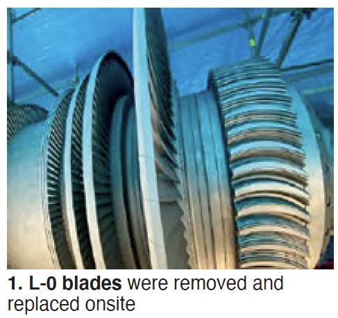
Speaker shares with colleagues IP rotor findings and the two blading replacement options considered: restore to original design or leave as is. For the LP section, L-0 blades were removed and replaced onsite with mix-tuned blades (Fig 1); no balancing was performed. Unit was returned to service with no vibration or operational issues.
GE D11 casing cracks and repairs (2013-2020)
This presentation affords the opportunity to learn about the casing cracks and repairs made to a D11 steam turbine over the unit’s life from COD in 2002 through its second major in 2020. The first major, conducted in 2013 after nearly 45,000 operating hours and nearly 1700 starts, was planned for 49 days but took 95. Operating hours at the start of the second major numbered about 98,000, but there were only about 120 starts in the second interval.
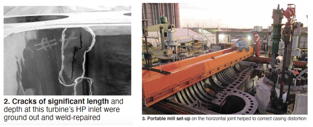
Inspection of the HP casing at the first major revealed cracks of significant length and depth in the inlet area (Fig 2). GE’s recommended welding procedure was reviewed by owner and plant personnel. It included a post-weld heat treatment of about 1200F for the entire HP/IP casing. However, during this process the casing was humped, requiring another repair. It involved removing about 200 mils of material from the horizontal joint in the HP inlet area to correct the distortion (Fig 3). Plus, machining of the diaphragm fits/steam seal faces and casing reliefs with a boring bar.
With the turbine gods smiling, the unit was reassembled and restarted with no vibration issues or rubs in January 2014. No issues were in evidence prior to the second major. But staff was apprehensive as the unit was opened for inspection. One crack was found on both the upper and lower halves that required attention. It was ground out and weld-repaired.
Creep and diaphragm dishing were in evidence and the experts conducting the investigation said they expected a casing replacement might be required at the next major. In sum, personnel believe that heavy cyclic duty prior to the first major contributed to the severe cracking corrected in 2013. Baseload service in the second interval mitigated the underlying issue. But the lingering question was the following: At what point does the plant quit trying to repair and evaluate retrofit options.
GE rotor indication recovery
This analysis and repair of the rotor for a 523-MW GE G2 turbine is based on experience gained at the gas-fired steam plant since COD in 1973. Steam conditions for the unit, designed for baseload operation: 2270 psig/950F/950F. The first clue something was amiss was vibration identified in 2019—especially on the T1 and T2 IP bearings on coast down.
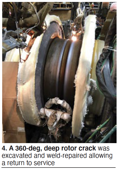
The unit was operated in the partial-arc mode and vibration occurred at certain valve settings. Going to full-arc admission eliminated the vibration. The unit tripped on high vibration in summer 2019. Upon disassembly, a 360-deg circumferential crack was found on the discharge side of the first-stage wheel transition area.
The rotor was shipped to the shop for additional inspection and evaluation. Cracking was found in other areas as well. Excavation of the first-stage crack was initiated, experts believing it to be at least 3 in. deep; it was 8 in. (Fig 4). Some details of the effort are shared in the presentation.
Outage duration was approximately 230 days. Since returning to service for the summer 2020 run, the unit has behaved well. However, the extensive weld repair reduced the rotor’s remaining life. A new like-kind rotor, in manufacture, is planned for installation early in 2022.
Post mortem: A review of vibration data from 2010 revealed clues regarding rotor cracking. The unit had operated for years outside the service parameters for which it was designed. The fast- start/fast-ramp paradigm adopted, with 500-deg-F thermal ramps and a dispatchable load range of from 50 to 500 MW, took a toll. The replacement rotor in manufacture has design enhancements to better accommodate today’s challenging operation requirements.
Special technical presentations
MD&A: Using turbine performance to improve your maintenance strategy
This presentation by James G Miller, PE, manager of performance services for MD&A, is a valuable primer for plant personnel participating in their first steam-turbine outage and equally valuable as a refresher for more experienced engineers and technicians. Miller’s message: Use the results of (1) recent performance tests conducted with the unit in service, and (2) steam-path audits made in the early stages of the outage, to reduce both outage cost and duration.
Miller reminded attendees that performance losses are a sign of degrading conditions that adversely impact the plant’s bottom line. The outage affords the opportunity to use this information for pursuing repairs and upgrades of greatest economic value.
The speaker covered the basics of performance testing, and how to conduct the all-important steam-path audit, in his presentation, which is available on the Power Users website complete with formulas, calculation examples, a comparison of as-tested performance to reference data, etc.
Best practices in performance testing—such a making sure there’s at least 25 deg F of superheat when calculating turbine efficiency—are included in the PowerPoint, together with a list of diagnostic parameters or additional tests that can be used to further characterize the sources of loss—such as solid particle erosion (SPE), casing leakage, and valve leakage. Thermal scans are particularly valuable for identifying the locations of leakage (Fig 5).
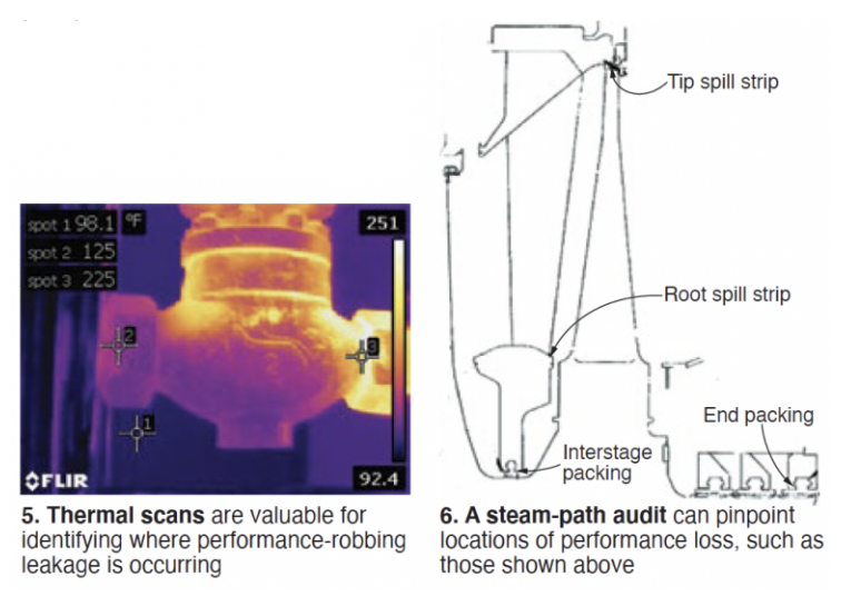
Examples of typical sources of performance loss identified during the steam-path audit include the following:
Seal leakage (Fig 6).
Surface roughness.
Change in trailing-edge blade profile.
Deposits.
Case studies identifying the reasons for performance loss in a reheat turbine at a combined-cycle plant, in a reheat turbine for a conventional steam plant, and in an industrial double-extraction condensing turbine are highly informative. For the first unit, performance testing revealed gross output had decreased by 2.3%. Excessive surface roughness, worn end packing, rubbed tip spill strips, and leakage by startup vents and HRSG drains were among the primary contributors to the loss.
A checklist of information to review in overhaul planning concluded the presentation.
Shell Lubricants: Choosing your lubricant not a one-size-fits-all
Lubricant selection is one of those subjects you might not think about for years, but when needed it’s good to have a backgrounder like this at your fingertips—or only a couple of mouse clicks away on the Power Users website.
Key discussion topics include these:
Base-stock evolution (Groups I through V).
Varnish.
Mitigation methods for varnish—including top-off fluids, filtration units, and fluid solutions (polyalkylene glycol, gas to liquid—lubricants made from natural gas).
Field experience.
Varnish elimination with polyalkylene glycol (PAG) was a focal point of the presentation, which included a review of experience since 2001 at two units that switched to PAG to eliminate servo valve issues caused by varnish. SlideshowSince then there have been no servo failures or trips while on PAG.
Recall that the stress experienced by a turbine lubricant contributes significantly to the ageing of petroleum oil, causing the non-polar fluid to oxidize. However, the resulting byproducts of decomposition are polar and insoluble in the base oil; they come out of the solution as varnish. Polyalkylene glycol, by contrast, is a polar fluid and, while it too oxidizes, the byproducts of decomposition are polar and infinitely soluble in the base stock. No varnish is produced.
Week Four
User presentations
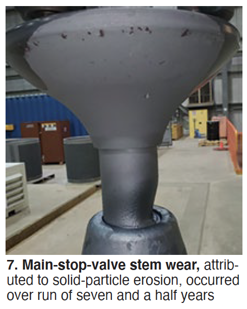
Maintenance of D11 stop valves and lessons learned
This is a fleet-wide perspective on valve maintenance based on operating-hour intervals and managed by the utility’s program called Optim. Focus is solid-particle erosion of valve stems (Fig 7) and seat erosion. Shearing of main stop/control valve strainer anti-rotation pin, LVDT nut looseness, and implementation of GE’s “Digital Valve” upgrade (Fig 8) are other topics—all well illustrated.
Three of the steam turbines addressed in the presentation rely on 32k operating-hour intervals for maintenance of their main stop/control, reheat stop/intercept, and LP admission stop/control valves. Another unit’s maintenance is based on 24k because it has experienced excessive scale buildup on the main and reheat valves. Findings and lessons learned are summarized in the slide deck available to registered users on the Power Users website.
Upgrading D11 valves
Presentation highlights valve findings and repairs, presents a historical perspective on valve indications, offers the owner’s perceived value of the OEM’s “Digital Valve” over in-kind replacements of damaged valves, identifies valve-replacement risks, how to plan for valve replacement, and operating experience to date with the “Digital Valve.”
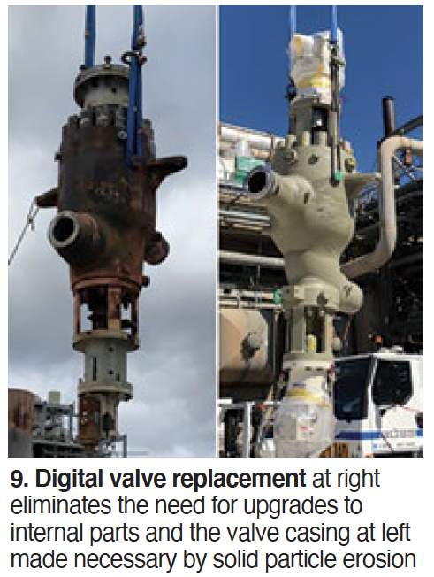
Lessons learned in the transition to GE’s digital valve (Fig 9):
Obtain drawings early to resolve any discrepancies prior to the outage.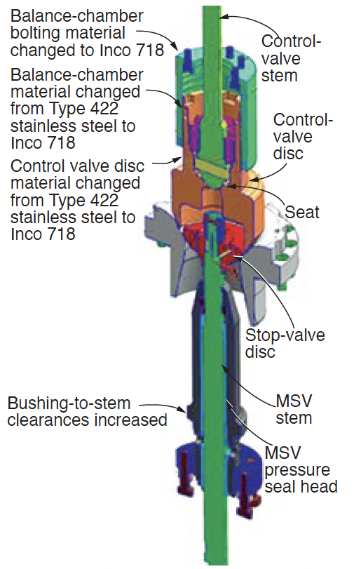
Ensure all parts and components associated with the new valve are onsite prior to the outage.
Order spare-parts kit along with the valve to assure availability of critical spares.
Ensure all specialty tooling for shell-arm load checks are available with spare parts.
Plan for new junction boxes and cable pulls to support below-seat drain relocations.
Contractor hired for electrohydraulic line mods must be trained on how to bend stainless-steel tubing.
Verify hardware on new valves is torqued and locking tabs are in place.
Benefits of the digital valve package include daily online testing, ability to monitor performance, and the promise of extended maintenance intervals. Operations personnel verified the digital valves operate quietly and smoothly.
Valve O&M considerations for steam turbines and auxiliaries
Eric Prescott, EPRI’s program manager for valves, discussed maintenance strategies for valves—including condition-, fleet-, value-, and time-based programs. His slides on maintenance workflow, system maintenance approaches, and valve condition monitoring are excellent primers for personnel new to your O&M team.
Prescott digs into the details of valve damages and operational stressors. For example, on the all-important subject of solid-particle erosion he examines the sources of particles, plus the importance of particle incident angle, steam velocity, and erosion-resistant materials for minimizing damage.
Coverage also includes fasteners and sealing elements, the spindle-guide bushing interface, Stellite hardfacing, and monitoring of valve castings for service fitness.
Special technical presentations
ARNOLD Group: Advanced steam-turbine warming for increased startup flexibility
Pierre Ansmann opened his presentation on “the most advanced turbine insulation combined with a high-performance heating system to improve startup flexibility,” by summarizing its value proposition thusly:
Increased in-market availability.
Lower startup costs.
Reduced thermal fatigue and longer mean time to repair for critical components.
Increased operating flexibility.
He reviewed alternative warming-system arrangements, rejecting those integrating the heating circuits in insulation blankets, installing the heater on a thin mattress below the blanket, and using glass-fiber-insulated heating cable. The optimal system for the upper casing, they said, is heater on metal mesh baffle, for the lower casing, permanent mounting of heating cable below the split line.
The ARNOLD system features interlocking high-performance blankets which conform perfectly to the turbine surface (Fig 10). High-quality materials and manufacturing, and long-term high-temperature resistance, allow the company to guarantee reuse of its insulation system for 15 outages without a decrease in efficiency.
Dozens of thermocouples, strategically located on the turbine, ensure proper heating. Each of the 18 or so heating zones has t/cs installed on the heating wires to double check if the zone is responding correctly and at the specified temperature. Below every heating zone, multiple t/cs are mounted on the casing to confirm even heating of the turbine.
Ansmann said a properly maintained ARNOLD insulation system can maintain your turbine in a hot-start condition for at least four or five days after shutdown. No preheating of the turbine is required prior to a start within this time period, reducing startup fuel consumption and auxiliary power.
Combining high-quality insulation and warming systems enables tight control of casing-to-casing and rotor-to-casing expansion during shutdowns. A goal for operations personnel to aim for, Ansmann said, is a homogeneous cooldown to maintain the temperature difference between the upper and lower casings to less than about 100 deg F.
EthosEnergy Group: Multiple upgrades improve D11 reliability
Owner/operators of the popular D11 steam turbine are sure to benefit from a review of this illustration-rich, 50+ slide presentation, easy to access in the Power Users archives. It covers the repair of 40-in. L-0 blades, and upgrades of Smart seals and the N2 packing box, among other things. The subject plant was a 4 × 2, 1240-MW combined cycle. COD for the unit upgraded was 2011; first major inspection in 2020.
Two rows of the damage-prone L-0 blades were weld-repaired prior to the outage to correct excessive leading-edge erosion (Fig 11). Cracking in the blade pin-finger dovetail roots also was addressed. Presentation provides details likely of value to anyone facing the same issues. Photos illustrate key steps in the process, including re-blading of the L-0 row.
The Smart seal upgrade was done to address rotor vibration caused by seal rubs. Experienced users know the HP/IP rotor is very flexible and sensitive to mid-span rubs. Detailed measurements of packing and tip-seal wear (average horizontal, top, and bottom) are presented. Heaviest rubs are identified with the lower-half horizontal joint. The speaker noted that although clearances generally are larger on the bottom, wear is substantial at all locations.
A seal developed to upgrade OEM seals to avoid rubs and wear during startup and shutdown, by way of additional clearance, is illustrated. Reduced vibration during startup is one benefit. Another is increased revenue, said to be upwards of $17-million for a typical 300-MW steamer over an eight-year run time. Information on estimated savings in fuel and carbon emissions also are presented.
N2 packing heads, which contain shaft seals between the HP and IP steam paths, have a history of horizontal joint leakage. This impacts performance because HP inlet steam leaks into the IP section. Plus, steam cutting occurs across the horizontal joint. The presenter highlights what his company’s experts say are design issues that prevent maintaining a closed joint. Described modifications are said to mitigate the problem.
STUG steering committee for 2021
Chairman: Seth Story, Luminant
Eddie Argo, Southern Company
Jess Bills, Salt River Project
Jake English, Duke Energy
Jay Hoffman, Tenaska
John McQuerry, Calpine
Matt Radcliff, Dominion
Lonny Simon, OxyChem
Founding members of STUG who recently retired from the committee are Bert Norfleet (2019) and Gary Crisp (2020)