By Dave Lucier, and Charlie Pond (deceased), PAL Turbine Services LLC
Turbine Tip No. 8 from the PAL solutions library applies to General Electric 5001N, 5002B, 6001B, 7001B-EA and F, and 9001EA and F gas turbines.
Proper operation of compressor variable inlet guide vanes (VIGV) is crucial for those gas turbines that have the “variable” design. Hundreds of components comprise a VIGV set and all must function properly and in unison. The operating cylinder must stroke; the rack must rotate; the vanes must all turn together to set the proper angle in the compressor inlet air.
Should a vane gear bind and not rotate properly or should one of the blades rub on the internal side of the compressor inlet casing (bellmouth), the consequences could be catastrophic. If a vane breaks off and liberates, it would be ingested into the compressor and cause the rotating and stationary blades to fail as well. Bad news!
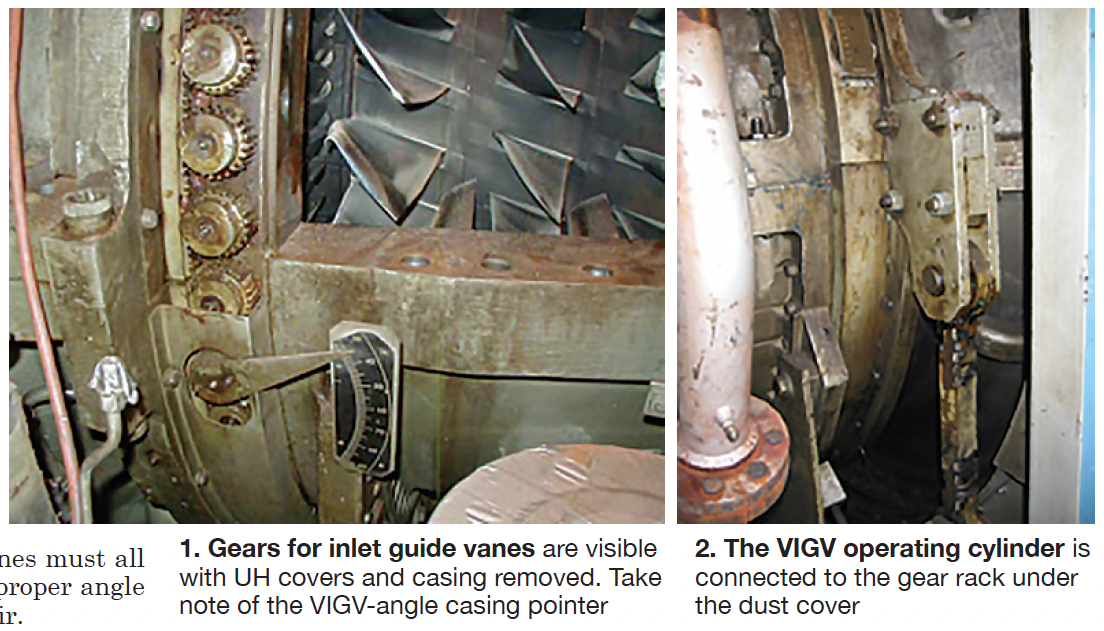
The VIGV set must rotate freely from the so-called “closed” to “open” position and back, depending on the turbine starting and operating design. End stops allow vane rotation through an arc of approximately 45 degrees. Free-moving vanes are vital to the proper startup, operation, and shutdown of the unit (Figs 1 and 2).

The closed, or starting condition, is set to reduce air flow during startup. This is done to mitigate compressor surge as the shaft speed and air flow increase. The VIGVs return to the closed condition during the shutdown sequence to again mitigate surge (vibration) and to prepare for the next start attempt.
During startup, as the turbine approaches operating speed (about 95% of rated speed), the VIGVs are signaled to rotate toward the open position. On most turbines, this means an angle change from approximately 44 to 87 degrees.
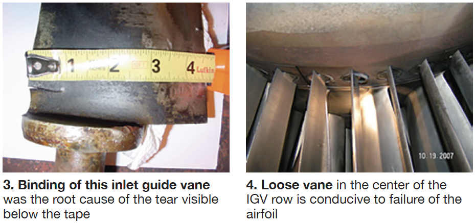
Fig 3 illustrates what can happen if a vane gear or bushing binds. The tear in this vane is about three-quarters of an inch in length. If the vane fails and eventually liberates, it could be sucked downstream and destroy compressor rotor and stator blades. A loose vane bushing also can cause a vane to bind, break off, and liberate (Fig 4).

Periodic testing of VIGV operation—quarterly recommended—can help identify potential issues before they morph into a problem and damage the unit. Here’s a typical procedure for testing the VIGVs on turbines with motor-driven hydraulic supply pumps:
- Confirm that the ac lube-oil pump (88QC) is operating and in the manual control mode. Recall that this pump feeds oil to the suction side of the hydraulic
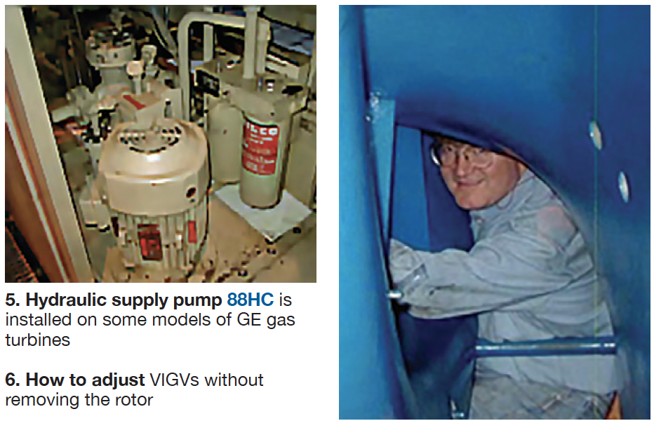
- Operate the ac hydraulic supply pump (88HC) in the manual mode to provide 1200-psig oil to the VIGV operating cylinder. Important: The 5001N engine has no 88HC, so a temporary hydraulic pump must be used. There is a pressure tap in the hydraulic manifold where a plug can be removed and the pump line A check valves prevents back-flow return to the lube system.
- Force the logic or simulate the pickup of speed relay 14 HS. Normally it is energized at 95% turbine
- Verify that 20TV is energized, so the VIGVs can move to their fully open Energize and/or de-energize the solenoid and observe the action, back and forth, closed to open. Be aware that some turbines have a solenoid valve called 90TV. One or the other is used to actuate the VIGVs between end-stop positions.
Logic-forcing methods will depend on which Speedtronic™ generation is applicable— that is, techniques will differ depending on whether the control system is a Mark I, II, IV, V, or VI. Recall that there is no Mark III system.
- Measure the end-stop positions of the VIGV (open and closed) with the pointer on the IGV ring and scale on the lower half of the compressor forward casing (refer back to Fig 1).
- Confirm the movement by measuring the voltage change of the linear variable differential transformers (LVDTs) associated with the travel of the VIGV hydraulic cylinder.
- Put eyes inside the compressor inlet casing (bellmouth) during the test to assure the vanes are all turning correctly in unison and not binding.

If binding is observed or suspected after several stroke cycles, a thorough borescope inspection may be required. Pond and Lucier LLC has developed a technique for servicing VIGVs without rotor removal (Fig 6). The service is offered at a firm price within a two-week window.


