

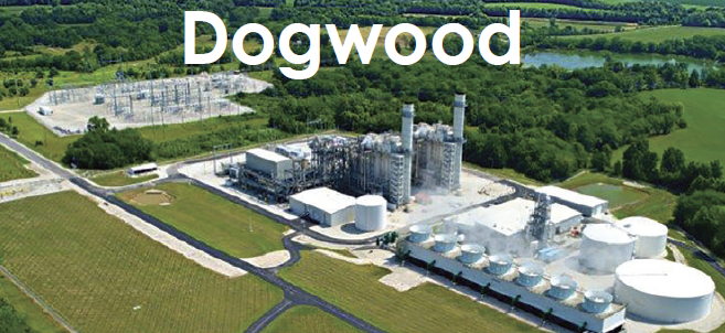
Dogwood Energy Facility
Owned by Dogwood Energy, City of Independence, Missouri Joint Municipal Electric Utility Commission, Kansas City Board of Public Utilities, and the Kansas Power Pool
Operated by NAES Corp
650-MW, gas-fired, 2 × 1 combined cycle located in Pleasant Hill, Mo
Plant manager: Steven Hilger
Sticking to a site map

Challenge. In the 17 years prior to implementation of its Confined Space Map, Dogwood had several occasions where a lock-out/tag-out (LOTO) involving a confined space was cleared, but remained open. After an HRSG door was left open following an outage, the plant started looking into ways to eliminate the potential for a recurrence, having to track over 150 confined spaces at the plant.
Solution. CRO Michael Davis, a member of the Safety Committee, had advocated for a visual way to account for confined-space status in the control room. After reviewing different ways to track confined spaces, he noticed that most of the solutions relied on technology that increased both cost as well as the CRO’s workload. He focused on finding a low-risk, low-cost, low-technology, high-results outcome.
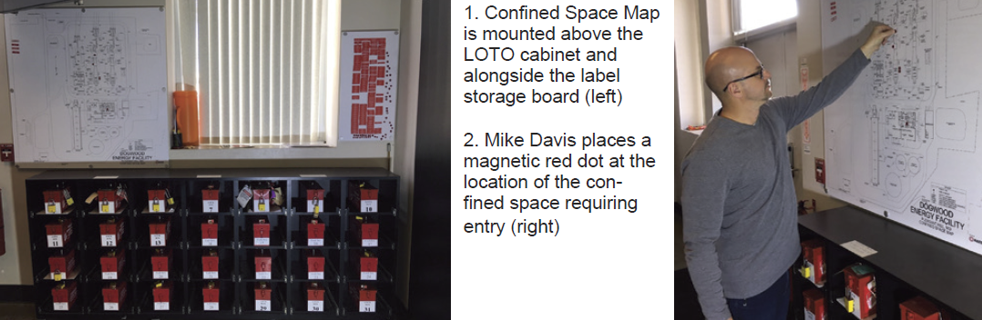
His idea was to create a site map showing the major equipment and some of the underground systems on a white magnetic board that included all the plant’s confined spaces. This map would be installed in the control room above the LOTO cabinet.
Davis worked with NAES drafting to develop a simplified site plan for the plant. In addition to the major equipment and underground information, the 45 × 45-in. map also includes the following:
-
- Safety showers in green.
- Tornado shelters.
- Water storage tanks and capacities.
- Manholes with system identification and numbers.
- Electrical manways.
- Hazardous chemical locations.
For work requiring a confined space, the CRO moves the magnet label for the associated confined space from the label storage board, at the right in Fig 1, to the site map’s left-hand side and then places a red magnetic dot at the location of the confined space on the site map (Fig 2). This provides personnel at Dogwood with a visual of the approximate location of open confined spaces at any given time. After a confined space has been closed and returned to its normal state, the label and dot are removed and returned to the storage board. Keeping the process simple helps its success.
The map also provides a visual representation of the plant to facilitate discussions among plant personnel and contractors, and to show evacuation routes and muster points, and all door swings.
Results. The Confined Space Map has been in use for more than a year. Dogwood personnel believe it has resolved the issue of leaving confined spaces open when they should be closed. In addition, the site map has provided the plant a good visual for discussions with contractors by identifying the locations of equipment and various underground manhole connections and safety showers. This is a safety and awareness win for the employees and contractors.
Project participants: Michael Davis, Eric Smith, Monty Ross, Jim Feitz, Mary Baptista, Steven Hilger.
Working safely on the package roof
Challenge. O&M personnel have a routine need to perform maintenance and inspections on BOP equipment located above the gas-turbine mechanical package. Access to this equipment required personnel to either climb an extension ladder or climb over railing from the GT access platform. Once on the roof, fall protection was required for the duration of work, restricting mobility. When multiple individuals were working on the roof at the same time, fall protection was more complex.
Solution. Dogwood worked with local firms to design and install an access point and handrail system to allow personnel to work on top of the mechanical package without the need for fall protection all the time (Fig 3).
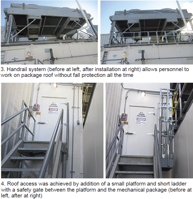
The easiest part of the project was to give personnel access to the mechanical package roof by adding a small platform and short ladder with a safety gate between the GT access platform and the mechanical package and by adding railing to three sides of the area (Fig 4).
The most difficult part of the project was determining the best way to allow forklift access to the roof to transfer equipment while still providing a system to minimize the need of fall protection when working on the mechanical-package roof. While Dogwood would have preferred a prefabricated swing gate for forklift access, a custom design was required to accommodate the plant’s configuration.
When removal of large equipment is required, personnel don their fall protection PPE and tie off before removing sections of the front handrail to allow access. Sleeves were installed on the mechanical package roof to allow for storage of the removed handrail sections during these evolutions. Safety signs were added to each handrail system reminding personnel that fall protection PPE is required when the handrail system is removed.
Results. Dogwood completed installation of the hardware on both GT mechanical packages in December 2019. Personnel performing work on top of the packages now have safe access to the roof and a handrail system to eliminate the need for fall protection during most work.
By eliminating the need for fall protection during most work, personnel have better mobility and more unrestricted access to the equipment located on top of the mechanical package and do not need to worry about tripping over fall protection lanyards.
Project participants: Chuck Berg and Steven Hilger
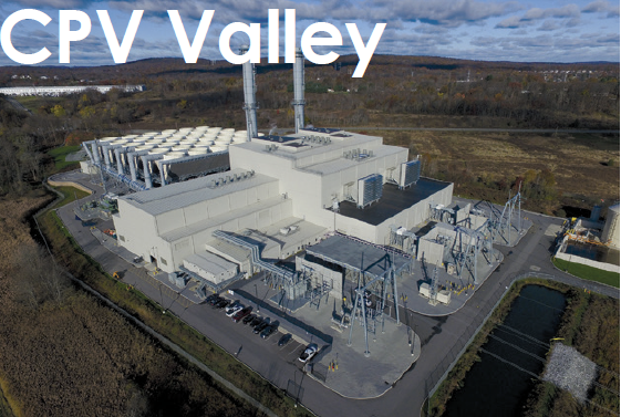
CPV Valley Energy Center
Owned by Competitive Power Ventures and Diamond Generating Corp
Operated by DGC Operations LLC
680-MW, gas-fired, 2 × 1 combined cycle located in Middletown, NY
Plant manager: Ben Stanley
Planning, collaboration key to outage management process
Challenge. IPPs with minimal staffing must be flexible and tactical when planning all outages. Utilizing a standardized (but adaptable) process for planning and execution helps keep employees and contractors safe and surprises to a minimum.
Solution. The plant’s O&M team works closely with asset-management staff, third-party support, and equipment OEMs to plan and execute outages. Key elements to the program are:
-
- An outage planning procedure that outlines the process for the team. This procedure is reviewed by the team before any upcoming outages.
- An outage summary document that states the purpose of the outage, the intended worklist, EHS planning, third-party participation, logistics, training, cranes and rigging, etc. It provides a narrative or “story” of the outage and evolves over time as the team refines the plan and gathers more detailed specifics around the work needed.
- A checklist that details the main components of the outage. Starting with the type of outage (routine, minor, CI, HGP, major) and expected duration, the planning checklist includes the following:
-
- Internal meeting schedules—including those for LTP/LTSA service planning, EHS planning, budget reviews, and meetings with third-party vendors.
- Outage-date requests and approvals to energy managers and ISO organizations.
- Outage project list, which comes from the work-management process in the CMMS. Work orders and PMs are appropriately identified, prioritized, and classified for each type of outage. This list is reviewed continuously during the routine work-management process (backlog and work planning meetings).
- A preliminary outage schedule is developed and shared with stakeholders early in the process. Critical-path items are identified and highlighted.
- Work schedules. Operator/maintenance crew shift schedules are reviewed and updated. Shifts are added where needed to support plant evolutions, EHS activities, operator training, etc.
- Special compliance inspections needed (pressure vessels, insurance/risk inspections, compliance metering).
- Rigging and lifting. A review of the need for lift plans and special rigging certifications is performed. In some cases, rigging/crane certifications require long lead times with third parties.
- Safety planning and third-party support (confined-space rescue, audit support, and site security).
- An EHS plan for the outage details items such as hazardous waste generated, inspection and audit planning, potentials for high-risk environmental issues, etc.
- Logistics. Parking, laydown, deliveries, additional office space, etc, are reviewed and an updated site map is generated.
- Budget and procurement. The business-administration and asset-management teams are fully integrated into the process with a detailed list of parts/inventory needed, executed contracts, purchase orders, and appropriate delegation of financial authorities. The team also maintains awareness of the potential for additional discovery work and prepares to communicate variances as they occur during the outage.
- In-house parts inventory is reviewed. Long-lead-time items identified should be ordered well in advance.
- Severe-weather contingency planning includes a review of forecasts, historical weather patterns, and lessons learned. Focus is increased on personnel safety during severe weather. Consideration is also given for activities such as water washes during freezing ambient temperatures, delays in deliveries during extreme weather events or snowstorms, emergency lodging/hotels, etc.
- Plans are developed for pre-, in-, and post-outage testing. Bear in mind that several tests are best performed during shutdown to minimize reliability risks (turbine auxiliaries, overspeed testing, fuel swapping, etc). There are other tests that should be performed only when the plant is offline. Finally, certain validation testing is performed during the restart process.
- NERC task review of the required compliance testing items is performed for NERC applicability.
- An integrated checklist is developed for critical site and contractor contacts. Since this changes for each outage, it’s important for staff to update the list specifically for each outage.
- External notifications. Regulators, emergency management organizations, and in some cases local government agencies, require notifications. Best practices have been adopted to make courtesy notifications to town supervisors, boards, mayors, etc. This prepares them for increased traffic in the area, additional vehicles parked onsite and potential inquiries from the public/media.
- Scope freeze. The O&M and asset managers determine the appropriate date for scope freeze so that no additional work items are planned for unless they fall under a higher amount of scrutiny by plant management. This helps to minimize schedule impacts.
- A lessons-learned meeting is conducted shortly after outage completion. Focus is on both when and where improvement is needed. As many stakeholders as possible are invited to the session. The list generated helps to create corrective actions and items to consider for the next outage. Continuous improvement is the goal.
-
-
- Final outage report includes the outage summary, detailed schedule, facility outage map, detailed costs and variance report, and final results of the work list.
Results. The collaborative efforts of the team lead to safe, well-planned, cost-effective, and well-documented outages. Utilizing the procedures and tools developed by the team helps to ensure that the outages are completed on schedule and on budget with minimal surprises.
Project participants: The entire O&M staff, including Donald Atwood, Ben Stanley, Ed Peters, Dave Engelman, Tanya Rovner, Josh Zimmer
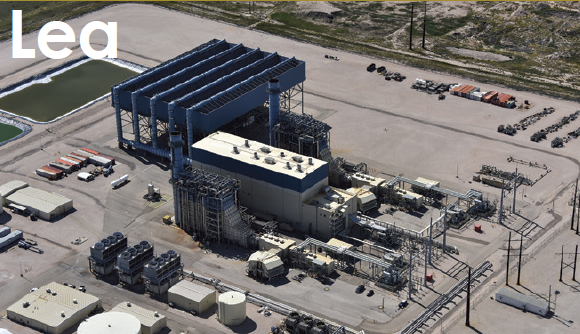
Lea Power Partners LLC
Western Generation Partners
Operated by Consolidated Asset Management Services
604-MW, gas-fired, 2 × 1 combined cycle located in Hobbs, NM
Plant manager: Roger Schnabel
Duplex lube-oil filter installed on BFP-skid fluid drive
Challenge. Under the original design, debris from any failed bearing in the system would be collected in the fluid-drive sump and then circulated through the system. This would cause damage to other bearings. Of particular concern was the debris that would accumulate inside the dead zones of the shell-and-tube lube-oil coolers. The design of those heat exchangers made them difficult to clean after a bearing failure. Debris hidden in the coolers would circulate onto the new bearings and cause premature failures.
Solution. Adding a set of duplex filters after the pumps and before the lube-oil coolers eliminated recirculation of bearing debris through the system (Fig 1).
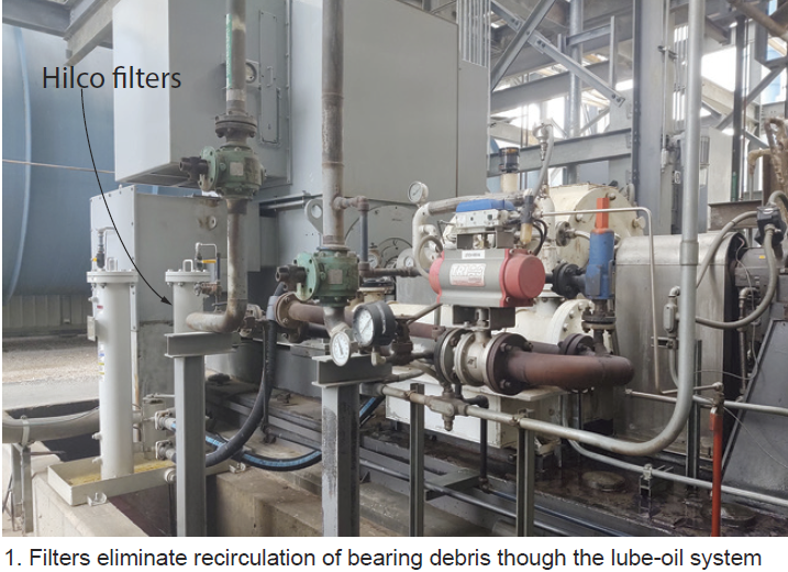
Results. After an upcoming overhaul, the heat exchangers will be cleaned thoroughly. They will remain clean because lube oil now is filtered. Even if a bearing failure were to occur, debris from that failure would be removed by the filters and not get into the lube-oil coolers. This will increase fluid-drive reliability and increase bearing life.
Duct-burner fuel-skid shut-off valve leakage test retrofit
Challenge. The duct-burner control system wasn’t designed to allow operators to leak-test valves in the fuel-gas system. The leak test is an insurance-company requirement.
Solution was to add a block valve between the last block valve and the duct-burner distribution manifolds, plus a bleed valve, vented to a safe location between the two block valves (Fig 2).
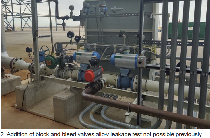
Results. The system now can be isolated from the duct-burner manifolds and tested for leaks. A leak test was performed during a recent outage and satisfied insurance-company requirements.
Redundant filter system for ammonia injection skid
Challenge. The original design had a filter before the single valve controlling ammonia flow to the HRSG. Debris from the ammonia tank would collect in the tubing and plug the filter. An outage was required to correct this problem each time the filters clogged up.
Solution was to add a second filter in parallel to the original one with all the required block valves, drain valves, and pressure differential gages, thereby enabling one line to be taken out of service without stopping ammonia flow to the HRSG (Fig 3).
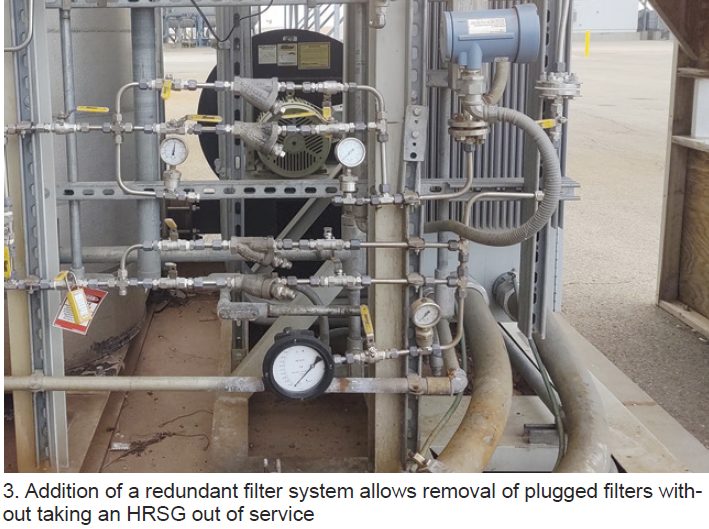
Results. After this modification was completed, the second filter was placed in service and blocked off. Once the filter in service shows sufficient pressure differential, the standby filter is lined up. Thus, a filter can be changed-out without taking an HRSG out of service.
Redesign HRH bypass steam diffuser in the ACC duct
Challenge. The hot-reheat bypass diffusers in the air-cooled-condenser duct were failing regularly. The diffusers were fabricated of ½-in. plate in two sections with ½-in. holes totaling 50-in.² of flow area. The holes were very close together (Fig 4) and a combination of flow and vibration would break the metal between the holes. In the first 10 years of plant operation these diffusers had failed twice.
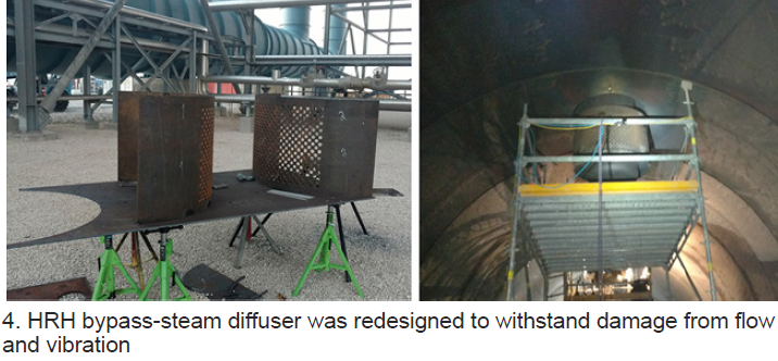
Solution. The solution was to redesign the diffuser area, using the same ½-in. plate but drilling 1-in. holes on 2-in. centers for the same total flow area. This increased the distance between holes and therefore making the entire diffuser much stronger to withstand the flow and vibration.
Results. Following the installation of the newly designed diffusers, the ACC duct was inspected after about four months of operation. The diffusers showed no damage or cracks. Plant personnel plan to monitor diffuser condition whenever the opportunity exists.
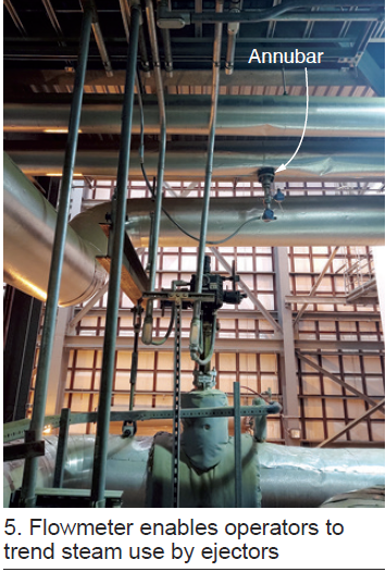
Flowmeter installation on the air-ejector steam line
Challenge. As designed, the plant didn’t have a flowmeter to measure the amount of steam used by the ACC air ejectors. This made it difficult to evaluate ejector performance.
Solution was to install an annubar in the steam line common to all the ejectors (Fig 5).
Results. After flowmeter installation, the plant was able to trend steam use by the ejectors during startups and normal operation. Flow measurement has helped in the troubleshooting of ejector issues that could not have been diagnosed previously.
Upgrade heat-trace control panels to alert CRO with DCS alarm
Challenge. Heat-trace control panels (HTCP) supplied with the plant included individual breaker-condition indicator lights on the front of the panel for local indication of a problem. During cold-weather operation, plant operators were making frequent rounds to verify there were no tripped breakers on the HTCPs that could lead to plant reliability issues caused by frozen instrument sensing lines.
Solution. Install new cable runs from HTCPs to the control room DCS. Wire the relay board to create an alarm series circuit such that if any breaker trips an alarm is generated on the DCS. In addition, create new alarm points and graphics screen on the DCS (Fig 6).
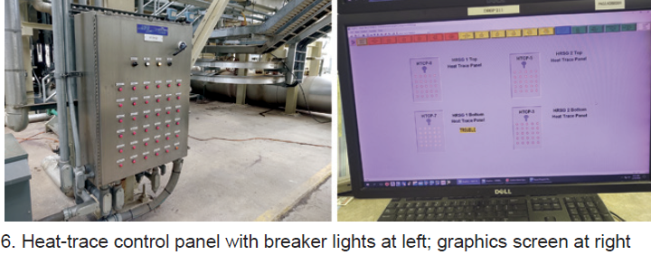
Results. After the HTCP remote alarms were implemented, the incident rate of frozen transmitter sensing lines was reduced by early detection which allowed faster corrective action. The HTCP DCS alarm functionality has improved overall facility cold-weather reliability.
Project participants: Roger Schnabel, Carlos Sanchez, Richard Shaw, Kelvin Mendenhall, and Tyler McCoy
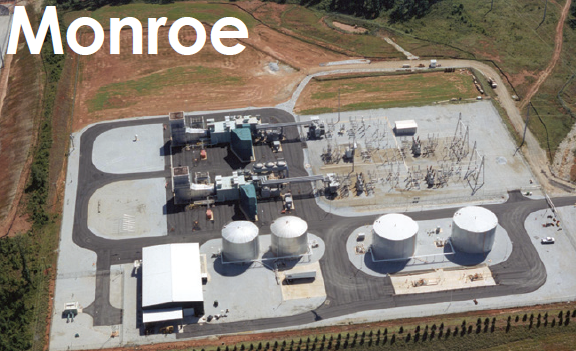
Monroe Power Co
Owned by Southeast PowerGen LLC
Operated by Cogentrix
380-MW, gas-fired, two-unit, simple-cycle plant located in Monroe, Ga
Plant manager: Mike Spranger
Turbine-enclosure ventilation-system upgrade
Challenge. During a test run following a planned maintenance outage, one unit experienced a fire-system high-temperature trip in the turbine enclosure which caused a turbine trip. One of the contributing factors to the fire-system trip was that the turbine enclosure ventilation system did not respond to the rising temperature fast enough.
Solution. Staff designed and installed upgraded ventilation system controls. The thermostats by the door were replaced by RTDs mounted on the ceiling so that the ventilation system is operating based on the hottest areas in the turbine enclosure. Louvers operate independently from the fans at a lower-temperature setpoint, allowing heat to escape naturally and reduce the stress on fans and motors. A ventilation graphics screen was added to the DCS so a control room operator can monitor and operate the system remotely.
Results. The ventilation upgrade, completed for less than $500 per unit, improves the operation and reliability of the gas turbines.
Project participants: James Goins, Chris Harris, Scott Hobbs, Charles Gibson, Nick Sanz, Bly Crane.

