If you have never attended a STUG event, the summaries of user presentations from Week Three and Four of the 2020 virtual meeting in this issue of CCJ ONsite will encourage your participation in future in-person, live events. The information shared at these forums, vital to your professional development and your plant’s success, is available only through Power Users.
Registered owner/operators also can access the user experiences and presentations made by third-party products/services providers during Week One of STUG2020 (November 11) on the Power Users website. For technical presentations made by the OEM during Week Two (November 18), visit GE’s MyDashboard website.
User presentations
Alstom MI with IP blade replacement and L-0 replacement
 Reviews the planning and execution challenges associated with a recent steam-turbine major inspection, incorporating lessons learned. Background: The 282-MW Alstom steam turbine serving a 2 × 1 F-class combined cycle began commercial operation in 2003 and had a service history spanning 100k operating hours and nearly 600 starts. HP and IP steam conditions were 1050F/1975 psig and 1050F/483 psig, respectively.
Scope of work for the full-train (HP/IP/LP/Gen) major inspection included the following:
-
- Inspect HP turbine stop/control valve inspections, replace Radax blade row, and provide new rotor and casing seals.
- Inspect IP turbine intercept stop/control valves, replace Radax blade row and first- and second-stage rotating blades, install new rotor and casing seals.
- Replace LP turbine L-0 blades and refurbish LP gland housing.
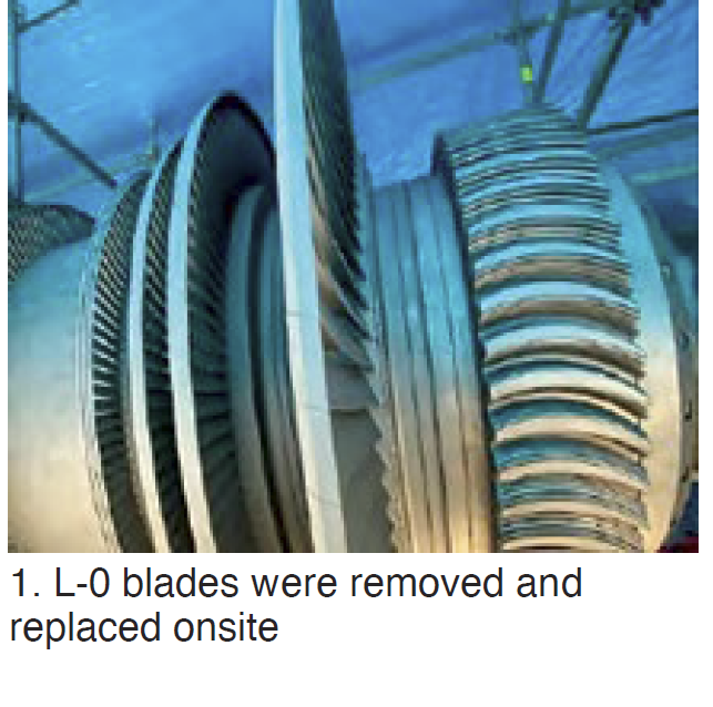
Speaker shares with colleagues IP rotor findings and the two blading replacement options considered: restore to original design or leave as is. For the LP section, L-0 blades were removed and replaced onsite with mix-tuned blades (Fig 1); no balancing was performed. Unit was returned to service with no vibration or operational issues.
GE D11 casing cracks and repairs (2013-2020)
 This presentation affords the opportunity to learn about the casing cracks and repairs made to a D11 steam turbine over the unit’s life from COD in 2002 through its second major in 2020. The first major, conducted in 2013 after nearly 45,000 operating hours and nearly 1700 starts, was planned for 49 days but took 95. Operating hours at the start of the second major numbered about 98,000, but there were only about 120 starts in the second interval.
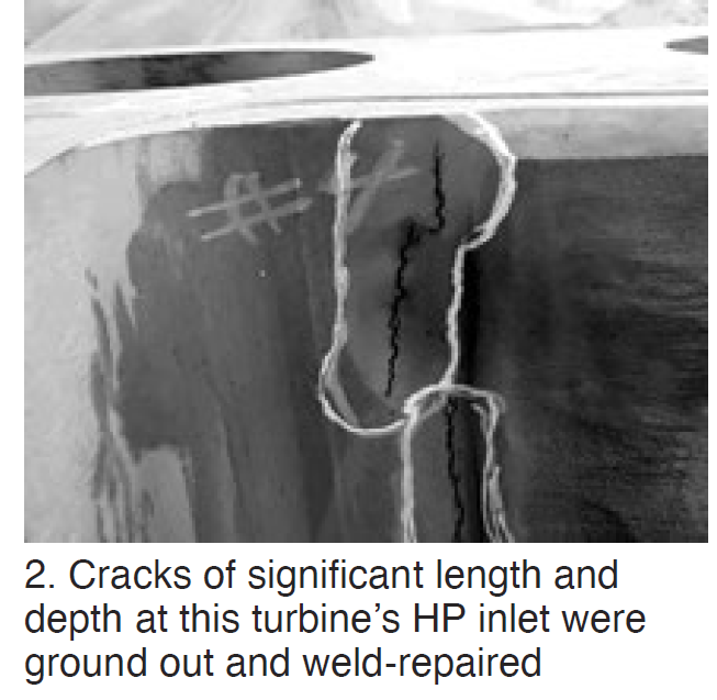
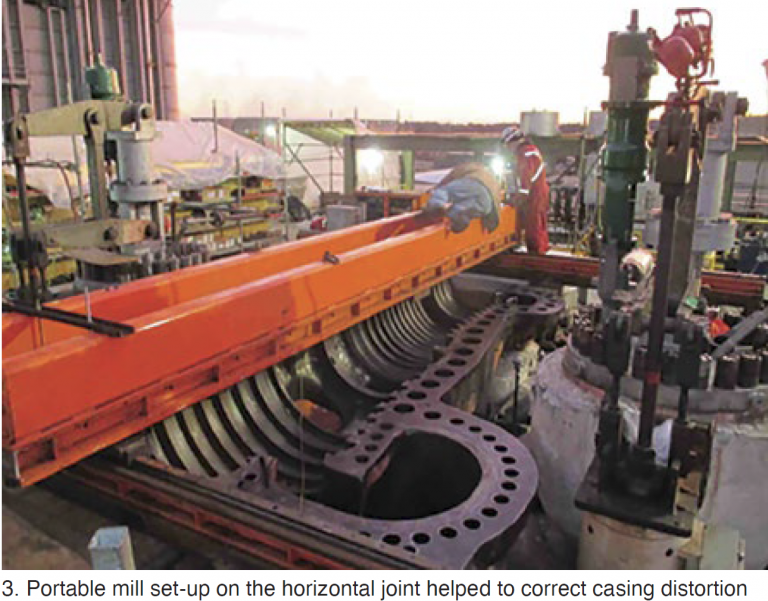
Inspection of the HP casing at the first major revealed cracks of significant length and depth in the inlet area (Fig 2). GE’s recommended welding procedure was reviewed by owner and plant personnel. It included a post-weld heat treatment of about 1200F for the entire HP/IP casing. However, during this process the casing was humped, requiring another repair. It involved removing about 200 mils of material from the horizontal joint in the HP inlet area to correct the distortion (Fig 3). Plus, machining of the diaphragm fits/steam seal faces and casing reliefs with a boring bar.
With the turbine gods smiling, the unit was reassembled and restarted with no vibration issues or rubs in January 2014. No issues were in evidence prior to the second major. But staff was apprehensive as the unit was opened for inspection. One crack was found on both the upper and lower halves that required attention. It was ground out and weld-repaired.
Creep and diaphragm dishing were in evidence and the experts conducting the investigation said they expected a casing replacement might be required at the next major. In sum, personnel believe that heavy cyclic duty prior to the first major contributed to the severe cracking corrected in 2013. Baseload service in the second interval mitigated the underlying issue. But the lingering question was the following: At what point does the plant quit trying to repair and evaluate retrofit options?
GE rotor indication recovery
 This analysis and repair of the rotor for a 523-MW GE G2 turbine is based on experience gained at the gas-fired steam plant since COD in 1973. Steam conditions for the unit, designed for baseload operation: 2270 psig/950F/950F. The first clue something was amiss was vibration identified in 2019—especially on the T1 and T2 IP bearings on coast down.
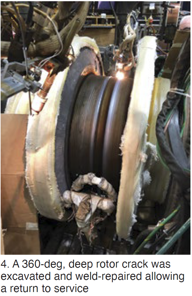
The unit was operated in the partial-arc mode and vibration occurred at certain valve settings. Going to full-arc admission eliminated the vibration. The unit tripped on high vibration in summer 2019. Upon disassembly, a 360-deg circumferential crack was found on the discharge side of the first-stage wheel transition area.
The rotor was shipped to the shop for additional inspection and evaluation. Cracking was found in other areas as well. Excavation of the first-stage crack was initiated, experts believing it to be at least 3 in. deep; it was 8 in. (Fig 4). Some details of the effort are shared in the presentation.
Outage duration was approximately 230 days. Since returning to service for the summer 2020 run, the unit has behaved well. However, the extensive weld repair reduced the rotor’s remaining life. A new like-kind rotor, in manufacture, is planned for installation early in 2022.
Post mortem: A review of vibration data from 2010 revealed clues regarding rotor cracking. The unit had operated for years outside the service parameters for which it was designed. The fast-start/fast-ramp paradigm adopted, with 500-deg-F thermal ramps and a dispatchable load range of from 50 to 500 MW, took a toll. The replacement rotor in manufacture has design enhancements to better accommodate today’s challenging operation requirements.
Maintenance of D11 stop valves and lessons learned
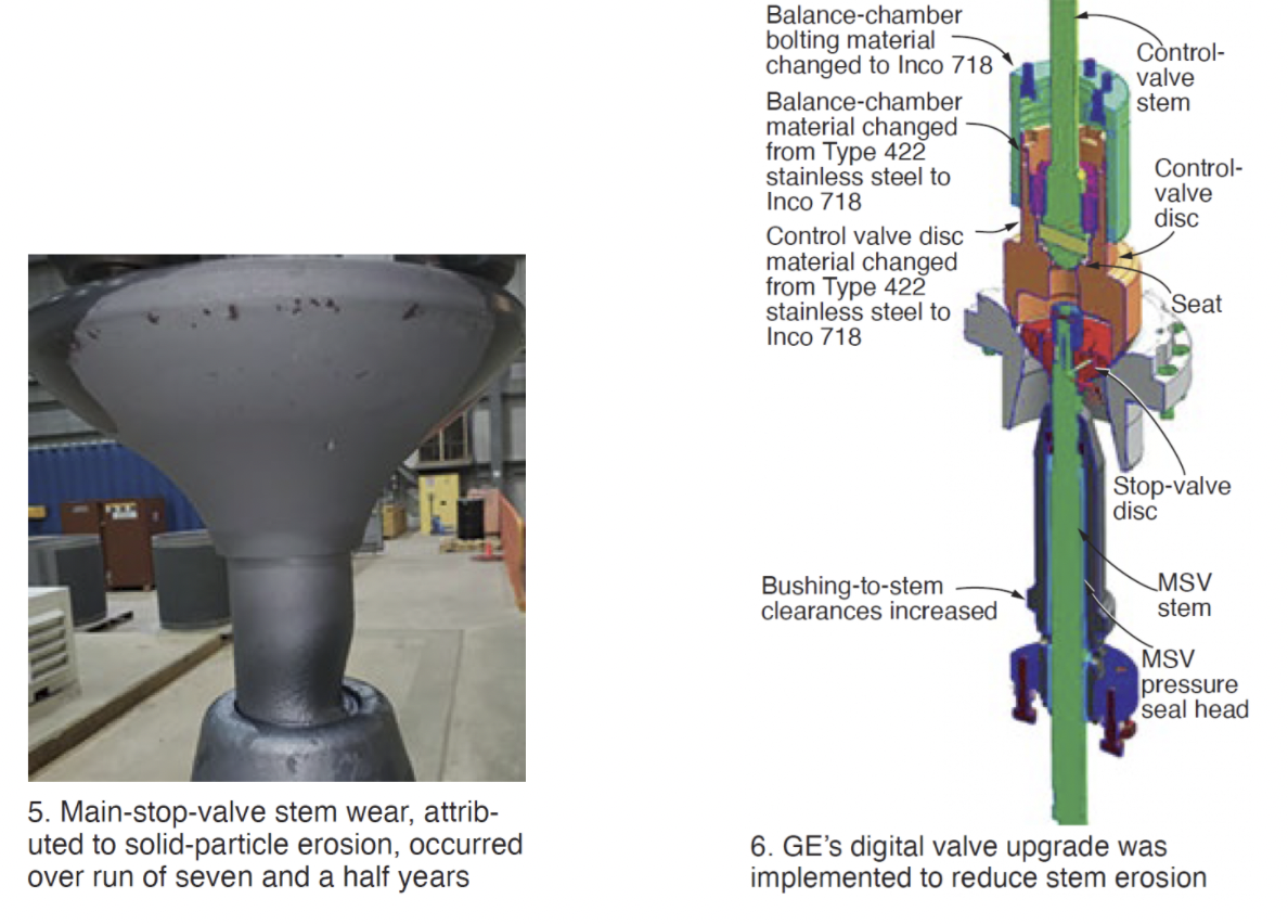
Fleet-wide perspective on valve maintenance based on operating-hour intervals and managed by the utility’s program called Optim. Findings focused on are solid-particle erosion of valve stems (Fig 5) and seat erosion. Shearing of main stop/control valve strainer anti-rotation pin, LVDT nut looseness, and implementation of GE’s “Digital Valve” upgrade (Fig 6) were other discussion points—all well illustrated.
Three of the steam turbines addressed in the presentation rely on 32k operating-hour intervals for maintenance of their main stop/control, reheat stop/intercept, and LP admission stop/control valves. Another unit’s maintenance is based on 24k because it has experienced excessive scale buildup on the main and reheat valves. Findings and lessons learned are summarized in the slide deck available to registered users on the Power Users website.
Upgrading D11 valves
 Presentation highlights valve findings and repairs, presents a historical perspective on valve indications, offers the owner’s perceived value of the OEM’s “Digital Valve” over in-kind replacements of damaged valves, identifies valve-replacement risks, how to plan for valve replacement, and operating experience to date with the digital valve.
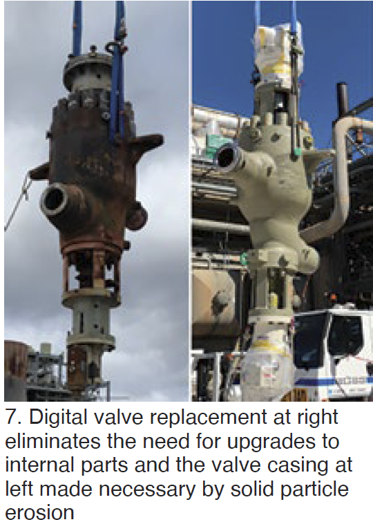
Lessons learned in the transition to GE’s digital valve (Fig 7):
-
- Obtain drawings early to resolve any discrepancies prior to the outage.
- Ensure all parts and components associated with the new valve are onsite prior to the outage.
- Order spare-parts kit along with the valve to assure availability of critical spares.
- Ensure all specialty tooling for shell-arm load checks are available with spare parts.
- Plan for new junction boxes and cable pulls to support below-seat drain relocations.
- Contractor hired for electrohydraulic line mods must be trained on how to bend stainless-steel tubing.
- Verify hardware on new valves is torqued and locking tabs are in place.
Benefits of the digital-valve package include daily online testing, ability to monitor performance, and the promise of extended maintenance intervals. Operations personnel verified the digital valves operate quietly and smoothly.
Valve O&M considerations for steam turbines and auxiliaries
Eric Prescott, EPRI’s program manager for valves, discussed maintenance strategies for valves—including condition-, fleet-, value-, and time-based programs. His slides on maintenance workflow, system maintenance approaches, and valve condition monitoring are excellent primers for personnel new to your O&M team.
Prescott digs into the details of valve damages and operational stressors. For example, on the all-important subject of solid-particle erosion he examines the sources of particles, plus the importance of particle incident angle, steam velocity, and erosion-resistant materials for minimizing damage.
Coverage also includes fasteners and sealing elements, the spindle-guide bushing interface, Stellite hardfacing, monitoring of valve castings for service fitness.
STUG steering committee for 2021
Chairman: Seth Story, Luminant
Eddie Argo, Southern Company
Jess Bills, Salt River Project
Jake English, Duke Energy
Jay Hoffman, Tenaska
John McQuerry, Calpine
Matt Radcliff, Dominion
Lonny Simon, OxyChem
Founding members of STUG who recently retired from the committee are Bert Norfleet (2019) and Gary Crisp (2020)