
AGT Services Inc’s Jamie Clark frequently is asked to present at user group meetings given his deep knowledge of generators. At last year’s (2022) Frame 5 Users Group conference, Clark conducted a well-received workshop on generator testing, inspection, and condition assessment which is of value to most participants in the Legacy Turbine Users Group—owner/operators of Frame 5, 6B, and 7B-EA GE engines.
If you did not participate in that workshop, the editors suggest a review of the 130-slide deck posted at www.powerusers.org. It contains scores of excellent photos/illustrations, many especially valuable to users who haven’t yet participated in a generator major. Jot down questions during your review and visit with Clark at the vendor fair accompanying this year’s meeting, July 17-20, in the Sheraton Grand at Wild Horse Pass (near Phoenix). He’s sure to welcome the discussion.
Stator
Roughly 80% of the slides Clark created for the workshop pertain to the stator (winding, endwinding support system, wedge system, and core iron); the remainder, the field (rotor). He began his presentation by stressing the need for good reference material, suggesting that IEEE 62.2, “Guide for Diagnostic Field Testing of Electric Power Apparatus—Electrical Machinery” be within arm’s reach.
Complete all visual inspections prior to cleaning stator components, Clark said, but clean them prior to electrical testing, that step being important to achieve accurate test results. Your inspection goals should be to identify detrimental deterioration/conditions, compare results to history, and apply intelligent and timely corrective actions.
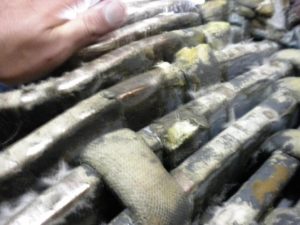
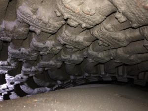
With regard to the stator winding, inspect for contamination (Fig 1), loose or broken ties (Fig 2), cracked paint, loose blocking, tape separation, corona activity (Fig 3), and global movement. In the endwinding support system check behind the winding for hardware looseness and felt supports. Note that loose or broken ties should be repaired to protect against endwinding motion and vibration.

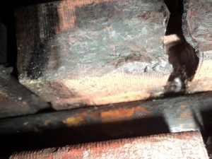
Core maintenance issues to be aware of include tightness, interlaminar insulation degradation, mechanical damage and lamination migration. Precursors of problems include iron oxide on the back of the core and on wedges. A simple knife test is a good way to assure tightness (Fig 4).

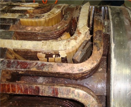
Damage to laminations may be smeared tooth tips, bending, overheating (Fig 5), burn spots. Core iron should be checked for migration in the outside space blocks (OSSB). Next check the first three rows of inside space block on each end for migration.
Important to conduct a wedge survey and to record the condition of the wedge system. Create a map that identifies the loose wedges and their locations.
At the end of the stator portion of his presentation, Clark recommended the following dc tests be conducted at a minimum:
- Phase (winding) resistance.
- 5- or 5-kV insulation resistance (Megger) and Polarization Index (a/k/a PI).
- Dc leakage.
- Power factor/Doble test.
- High-potential (HiPot).
- RTD resistance and Megger.
- El Cid.
Rotor (field)
Key elements of a visual inspection of the field, Clark said, are the following:
- Overall assessment of condition regarding dirt, oil, and other contaminants. Fields can get very dirty, Clark reminded the group, and stressed the need for cleaning before testing. To illustrate the impact of dirt on electrical readings he shared test results on one project that revealed 17,300 ohms before cleaning and 5850 megohms after steam cleaning.
- Look for arcing between wedges and in the wedge-to-retaining ring area.
- Note any hot spots on tooth tips at wedge joints.
- Examine retaining rings for condition; consider looking under the rings using a borescope (Fig 6).
- Verify collector ring is in good condition.
- Check for fan damage.
- Look closely for copper dusting.
Retaining rings typically are very reliable, especially those made of 18/18 alloy. Going beyond a visual inspection is suggested if pitting, cracks, and arc marks are found. If the rings are magnetic, mag particle testing would be the first step. If 18/18, the best results are produced with a combination of UT and eddy-current testing. The former is good for finding deep inclusions, the latter for identifying surface problems. Liquid-penetrant or Zyglo is another option if there are no deep inclusions.
Collector rings can suffer from worn surfaces, foreign object damage, and ghosting or foot-printing. The first generally can be corrected easily by removing some metal from the rings (Fig 7, 10 mils is typical).
Collector rings should be HiPot-tested with the field during rewinds. Note that a standard test and inspect will not include a HiPot of field components. If collectors are separated from the field winding they should be HiPot-tested individually after a good Megger test.
Recall that a good Megger indicates dry winding, low contamination, and good insulation. By contrast, a poor Megger indicates possible contamination, bad insulation, or a wet winding. If you are challenged by a low Megger, clean the collector rings and retest. If still low, separate the collectors and retest. If still low, tent the field and use heat and dehumidifiers to dry. Finally, if not much progress after several days, consider removing the retaining rings and doing an internal cleaning.
Other field electrical tests:
- Ac impedance test. Increase ac voltage from 0 to 130 V in 10-volt increments. Plot an impedance curve measuring ac volts and amps and look for step changes in the curve, which could indicate shorted turns. No step change indicates no shorted turns in static condition.
- Winding resistance. Be sure to correct to 25C and check results against the factory-issued resistance for your field as well as against previous test results. A decrease in resistance indicates possible shorted turns, a higher resistance broken connections/loose studs.
- Pole balance test. Apply a voltage across the collector rings and measure from one ring to the pole jumper, then the other. Rule of thumb: Measured voltages should be with 5% of each other. The challenge in conducting this test is to reach under the retaining ring and to put a test lead on the pole jumper.