

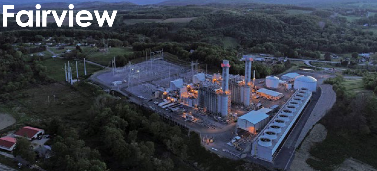
Challenge. Soon after commissioning, one of Fairview’s gas turbine/generators experienced stator-ground-fault trips attributed to isophase-bus (IPB) water ingression into potential transformer (PT) cabinets, followed by persistent lower-than-expected resistance readings. Doble Engineering was engaged to perform electromagnetic interference (EMI) testing on several components of the plant’s three power trains to assess their condition. Generators, step-up transformers (GSUs), unit auxiliary transformers (UATs), and IPB were suspect in each train (Fig 1).
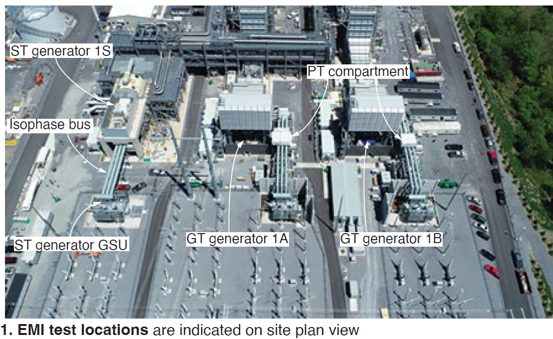
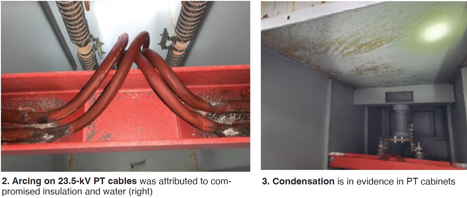
Following the first trip on stator-ground-fault 64 relay, damaged cables and condensation were found in a PT cabinet (Figs 2 and 3). To learn more on the importance of addressing grounding issues in a timely manner, read “IEEE standards may not sufficiently address grounding issues in rotor, stator windings,” by Clyde V Maughan, CCJ, 2Q/2013, p 7.
Solution. Given the extensive amount of IPB and connections, the CPV and NAES engineering teams advised the plant to perform EMI testing to identify other potential sources of arcing and abnormalities. An EMI diagnostic was conducted to determine the possible origin of the problems.
Recall that EMI testing is performed online and can detect several mechanical and electrical defects on generators, IPB, transformers, and motors. Defects in the bus connections or insulators generate radio-frequency signals that can be measured.
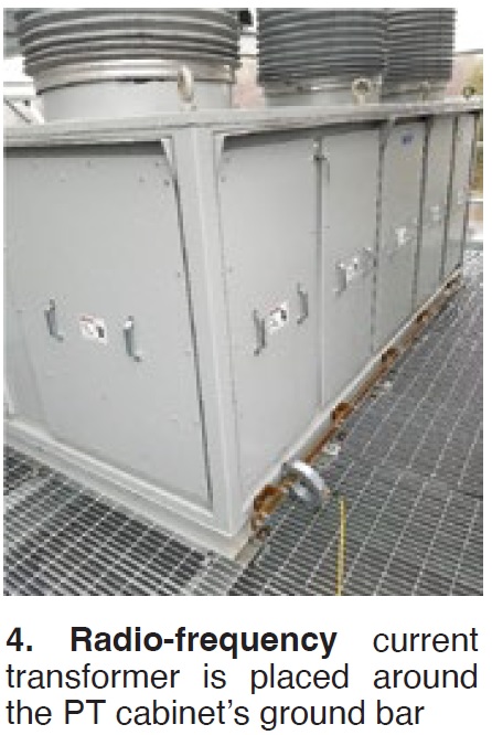 To perform an EMI diagnostic, a radio-frequency current transformer is placed around the neutral, a safety ground, or power conduit of the asset (Fig 4) to measure and identify the signals generated from the component or system defects. The EMI diagnostic method measures a broad spectrum of radio frequencies to evaluate signal patterns—including, but not limited to, corona, partial discharge (PD), and arcing.
Additionally, a handheld device is used in conjunction with the EMI signature to further identify the defect location. This device detects the EMI signals radiated from each component or system defect, allowing the technician to measure the intensity of the activity.
EMI testing is performed while the asset is in service and is a non-intrusive technique that will not cause the equipment to trip offline. A baseline measurement is helpful but not required for the analysis; therefore, maintenance recommendations are provided starting with the very first test, and the analysis helps to prioritize maintenance based on asset condition.
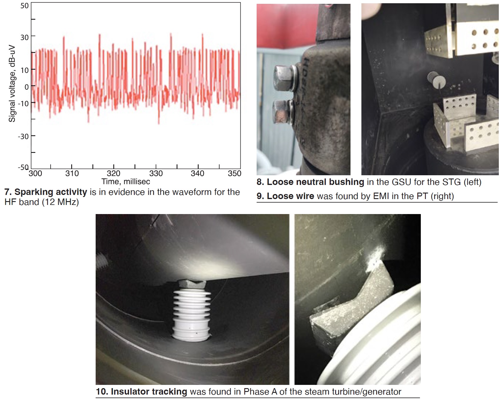
The generator, IPB, UAT, and GSU for each of the three units were tested and inspected. The table summarizes the most relevant findings. The EMI signatures in Figs 5 and 6 were acquired at different grounds on each component. The frequency ranges indicated on the EMI signatures, upon further and detailed analysis of the waveforms, revealed abnormal PD and sparking activities. Fig 7 is an example of a sparking waveform.
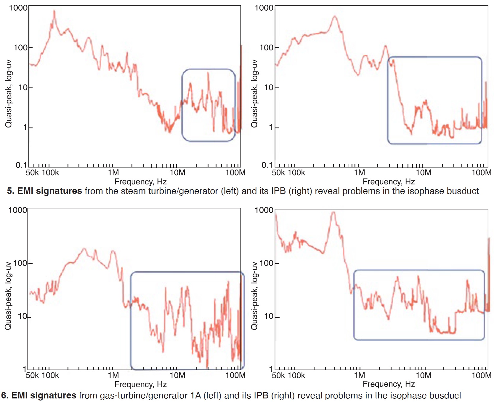
The activities detected typically are associated with insulation deterioration, defective connections, and loose hardware inside the IPB. To pinpoint the locations of the defects, a scan was performed with a handheld device to identify areas with high radiated EMI. After a thorough analysis, an internal inspection of different sections of the bus system was recommended.
Referring to the detailed EMI report provided by Doble, the locations identified in the table were highlighted on electrical one-line and 3-phase drawings. These marked-up prints were used to plan lockouts, scaffold erection, and inspections at the next planned outage. Figs 8-10 show examples of the findings in locations identified by EMI testing.
Results. Deficiencies were identified and corrected at each suspect location identified by EMI testing.
EMI testing enabled non-outage inspections of the electrical distribution system, thereby reducing the length of outage inspections and facilitating advance planning prior to the outage start date.
Given the success of the one-time EMI survey, CPV Fairview is installing a permanent EMI detection system. The team has initially selected the ST generator, IPB, and GSU for permanent monitoring.
A permanent installation may not fit everyone’s business model. As a minimum, we recommend conducting an annual survey or as-need surveys following repairs or the installation of new equipment.
Project participants:
CPV: Joe Michienzi, Preston Patterson, Tom Favinger, Ali Bibonge
NAES: Bill Lovejoy, chief engineer; Rick Marshall, maintenance manager; Jason Havash and Aaron Roberts, I&E technicians
Doble Engineering: Roberto Martinez and Oscar Montano
Fairview Energy Center
Owned by Competitive Power Ventures (CPV)
Operated by NAES Corp
1050-MW, 2 × 1 combined cycle powered by 7HA.02 gas turbines, located in Johnstown, Pa
Plant manager: Bob Burchfield

