A valuable turbine operating tip provided by Dave Lucier, founder and GM of PAL Turbine Services LLC, applies to GE Frame 5 gas turbines—most specifically the MS5001D, K, L, and LA packaged powerplants manufactured between 1961 and 1970 and serving in peaking and emergency-power applications.
Some users operating these engines have found that reliability issues associated with equipment other than the gas turbine proper can be addressed by limiting power (megawatt) output to a percentage of the original rating. It should not be surprising that a 50-year-old machine would exhibit signs of ageing. Here are a few instances where limiting output might be a wise strategy:
There are several “semi-permanent” ways to limit gas-turbine output, including the following:
-
- Generator experiences overheating at high loads, as sensed by RTDs in the stator.
- Reduction (load) gear vibrates excessively when operating at high power output.
- Turbine experiences vibration because of internal rubs attributed to casing distortion.
1. Limit switches on the load set point. Motor-driven rheostat (70-R4) can be used to reduce power output (Fig 1). One limit switch usually is set for 40% of travel. It establishes the “called-for” speed (offline at 5100 rpm) for the subsequent startup.
Another cam and limit switch is used to stop the motor when the travel reaches the end stop (at 100%). This cam can be loosened and rotated to stop the motor—at say 80% travel—for the purpose of curtailing generator output.
2. Gag adjustment of Young & Franklin fuel regulator. Another way for temporarily limiting power output involves “gagging” of the fuel regulator (Fig 2, left). This can be done with the turbine at cranking speed. Here’s how:
Start the turbine in the crank position and run up to 1000 rpm. Have one operator open the panel door and hold switch 43FS in the maximum VCO (variable control oil) position. Once the control-oil output pressure rises to maximum (typical setting is 180 to 200 psig), use the gag adjustment to temporarily lower the VCO. Look at recorded data for the baseload setting (usually about 160 to 170 psig).
Using a 3/8-in. nut driver, looking downward, turn inward on the gag adjustment (located under the plug shown in Fig 2, right), carefully counting the number of turns. Two or three complete rotations usually is all that’s necessary.
Next, restart the gas turbine and observe the new output limit with a lower VCO pressure than the previous baseload setting would allow. Example: 12-MW limit, when the original baseload setting might allow up to 15 MW.
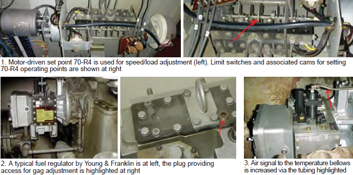
3. Air signal into temperature bellows. A third semi-permanent way to limit power output is to insert a temporary air signal into the temperature bellows. A tee can be installed in the air-signal tubing coming from device 65EP (Fig 3).
To illustrate, let’s say the temperature control will hold VCO pressure at 170 psig when on exhaust temperature control for the typical operating day, which is consistent with an output of 15 MW. For this condition the turbine exhaust temperature might be 930F and the air signal into the bellows approximately 22 psig from 65EP.
Install a tee in the tubing line to the bellows and raise the air pressure slightly. Example: 23 psig would limit the VCO to about 160 psig and exhaust temperature to 870F, reducing output to a nominal 13 MW.
Conclusion. Which method of output should you choose to help assure engine reliability? Lucier’s preferred method is to stop 70-R4 short of its end travel (80%). Second choice would be VCO gag adjustment atop the fuel regulator. Increasing the air signal to the temperature bellows is third on my list and would get consideration only when a short-term solution is necessary.