Shared by David Lucier, founder and GM, PAL Turbine Services LLC
Use correct names of gas-turbine components to avoid confusion
Components and auxiliary systems for GE gas turbines have specific names. It is important to use correct names when communicating with the manufacturer or service companies to be sure you’re understood. For some, it may be like learning to speak a new language, which can be called “GE-ology.”
In 1961, GE introduced the gas-turbine Packaged Power Plant. The company’s first PPP was the MS5001—a/k/a Frame 5. When introduced, the engine was designed to produce 12 MW, a rating that prevailed throughout the first half of the sixties. During the second half of the decade, demand for emergency power was unprecedented, with investor-owned electric utilities and municipalities placing orders for dozens of PPPs.
The PPP design had most of the auxiliary fluid systems located on the accessory base with the goal of minimizing installation and startup times. It included the following:
- Accessory gear with water, oil, and fuel pumps, and atomizing air compressor.
- Lube-oil (LO) tank integral to the I-beam base with oil pumps, coolers, filters, pressure regulators, etc, inside the base or above it.
- Hydraulic supply system using lube oil to provide high-pressure fluid for operating servo valves and the ratchet rotor-turning device, and for enabling clutch engagement. Earlier systems for clutch operation, diesel actuation, and ratchet engagement relied on high-pressure air.
- Fuel system components also atop the base included the following:
- Liquid-fuel pump and flow divider.
- Gas-fuel stop and flow-control valve.
- Cooling water system installed in the roof with radiators and fin-fan drive.
- Starting device (diesel engine or cranking motor) was on-base with jaw clutch.
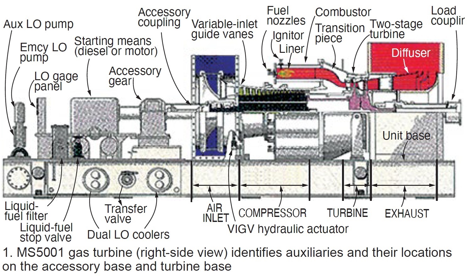
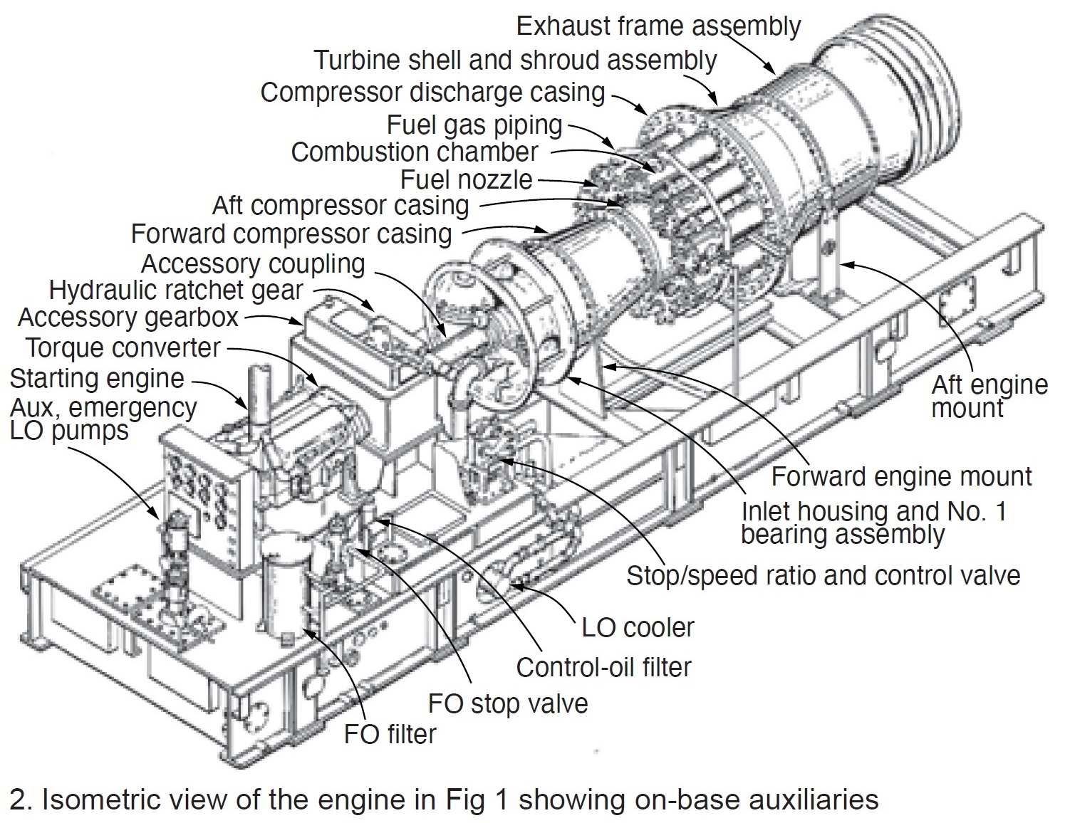
Fig 1 presents the right-side view of a gas turbine showing its auxiliaries and their locations on the accessory and turbine base. Fig 2 provides an isometric view. Most everything needed to operate the turbine is tagged. Some of the components not visible in Figs 1 and 2 include the fuel pump, 12-position fuel pressure selector valve and gage for each combustor, and liquid-fuel flow divider. Other devices that would be installed on the gas turbine include two compressor bleed valves, two igniters (a/k/a sparkplugs), and ultraviolet flame detectors.
Given the availability of a cured concrete foundation onsite, PPP installation typically took less than two months. Bear in mind that this was the first time the gas turbine was “introduced” to its generator, load gear, control cab, generator breaker, and protective devices—all manufactured at GE facilities in other cities.
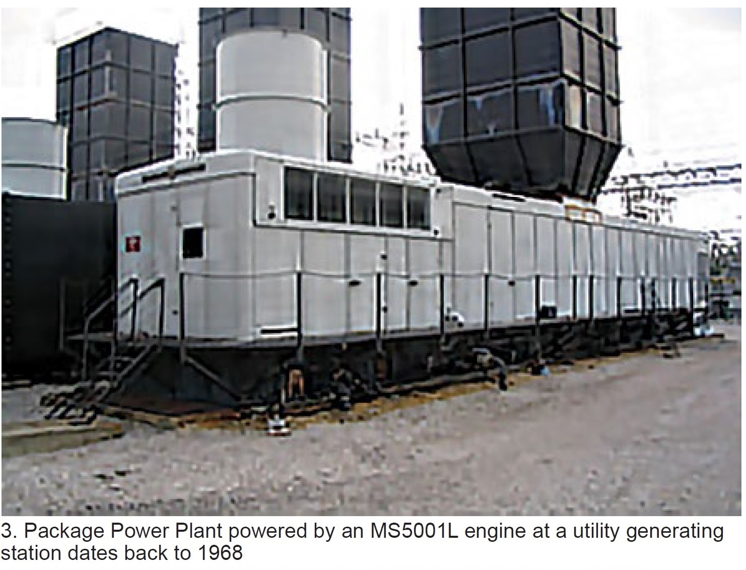
A typical PPP (Fig 3) shows the accessory base (left), gas turbine and exhaust (center), and generator (far right). This configuration of major components prevailed for over 50 years in the design of most GE Frame 5 and 6 gas turbines—even those installed inside buildings.
A simple way to check gas-turbine performance
GE gas turbines installed in electric generating plants from the mid-1960s to the late 1980s operate infrequently today—typically confined to peaking and emergency service—given the availability of more-efficient machines for mid-range and baseload duty. However, when your legacy engines do run it is good to know if they are operating “up to snuff.”
There’s an easy way to do this knowing compressor discharge pressure and exhaust temperature, calculating the pressure ratio, and plotting this information on the OEM’s performance graph provided in the plant’s Control Specifications.
Below are the steps involved, using the MS5001L gas turbine to illustrate the process. These so-called 5L turbines were designed with NEMA (National Electrical Manufacturers Assn) ratings of approximately 15 MW for a compressor inlet temperature of 80F and site elevation of 1000 ft (14.17 psia).
First, access the following information from the control system display (Fig 4) at full speed/no load (FSNL):
- Turbine exhaust temperature (TXA).
- Compressor discharge pressure (PCD).
- Fuel-pump stroke reference (VCO).
The data are repeated in the caption to facilitate readability. Given the compressor inlet pressure is 14.39 psia from site data (if not available, use the standard 14.7 as its impact will be minimal, especially for legacy turbines), the pressure ratio (CPR) can be calculated as follows:
CPR = [76.1 (PCD) + 14.39] ÷ 14.39 = 6.29.
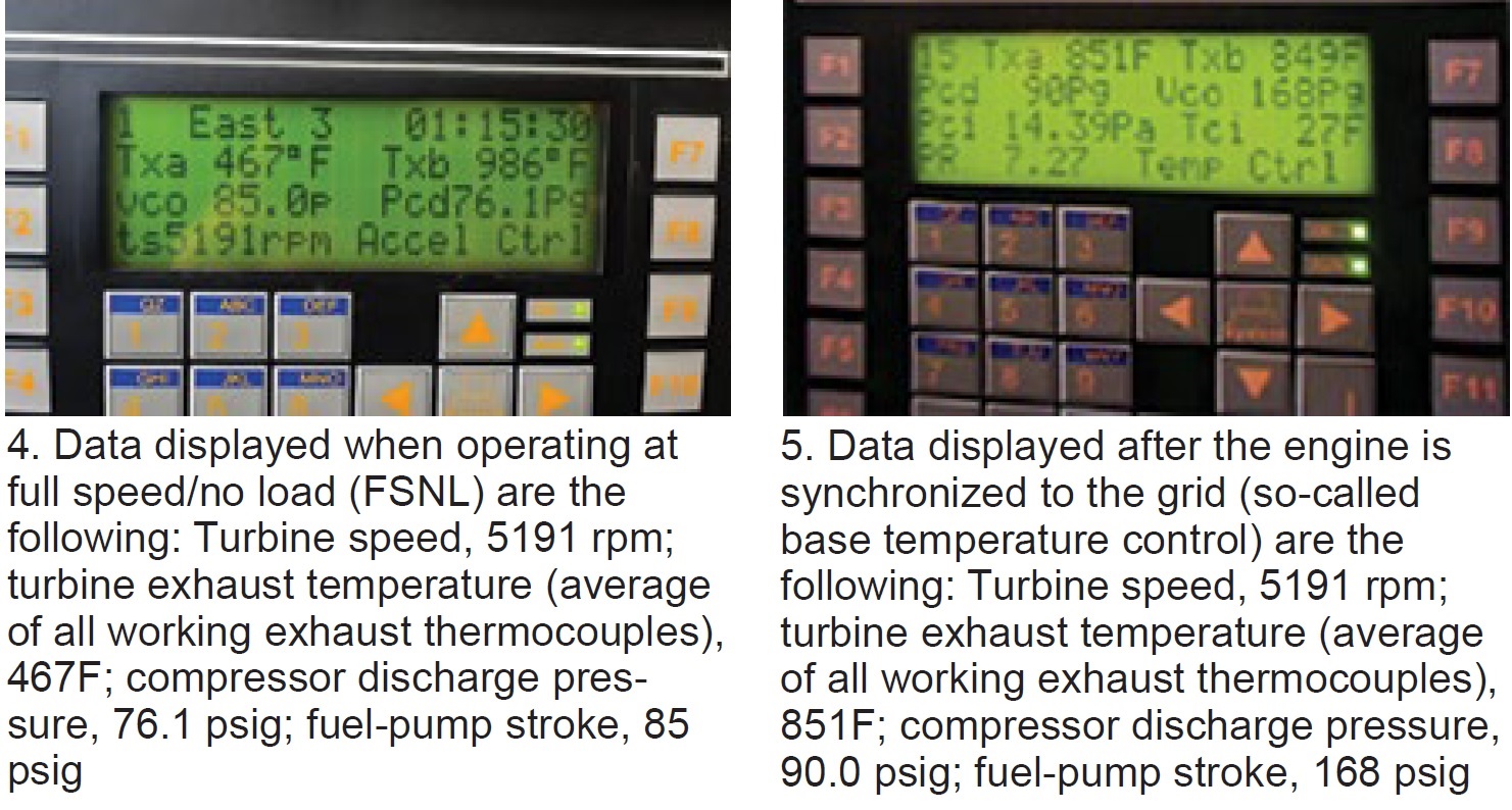
Since speed is constant at FSNL, in preparation for the generator to supply power to the grid, consider that a new operating “plateau” has been reached: synchronous speed. Thereafter, the data of interest increase in direct relation to fuel flow to the combustors (Fig 5).
Again, the data are repeated in the caption to facilitate readability. As for the previous calculation, the compressor inlet pressure is 14.39 from site data and the pressure ratio at baseload is the following: CPR = [90 (PCD) + 14.39] ÷ 14.39 = 7.25.
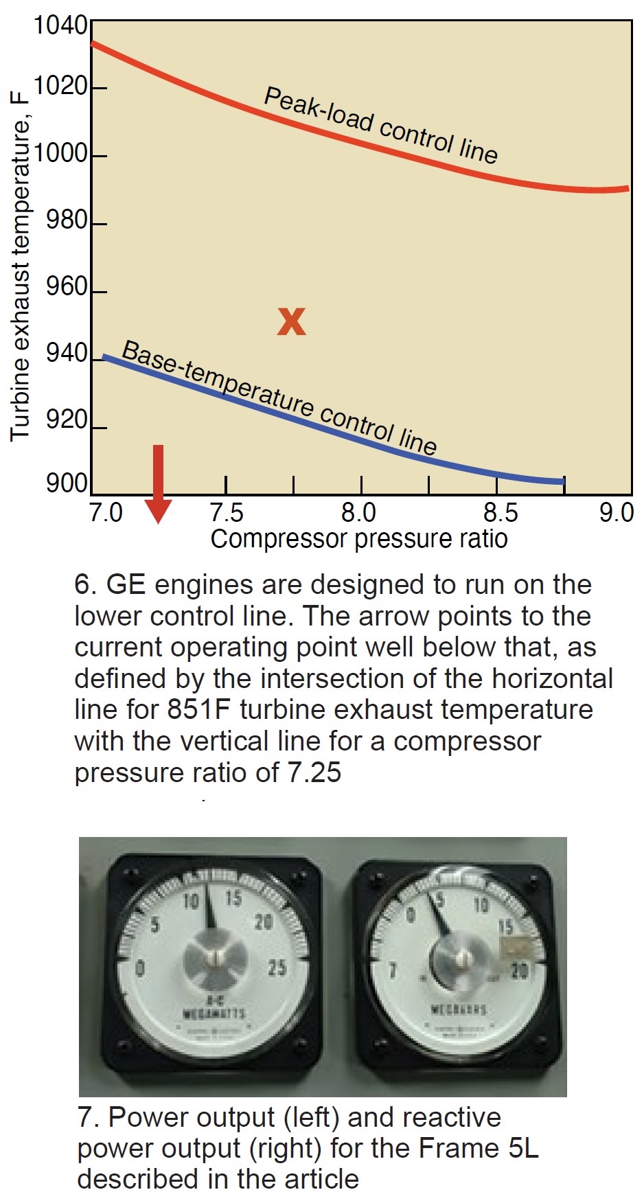 Next, go to Fig 6 and plot the average exhaust temperature at full load (851F from Fig 5) against the compressor pressure ratio of 7.25 at baseload. That point occurs well below the base temperature control line, as the arrow indicates. Important to note that GE engines are designed to run on the lower control line. When operating below this line, the unit is under-firing—that is, performing below the design rating. Fig 7 illustrates this with a power output of 12 MW, lower than expected with 3.5 MVAr of reactive power.
Of course, you might choose to operate slightly below the engine’s design rating to maintain its reliability and minimize wear and tear, given the unit’s age. You can do this by adjusting the fuel regulator to reduce exhaust temperature.
Performance analysis. For the Frame 5L example, power production increases from 0 MW at FSNL to 12 MW, because fuel flow to the compressor increases during the ramp up in output. During this transition, compressor discharge pressure goes from 76.1 to 90 psig—a rise of only 13.9 psi, which is considered low and indicative of something being wrong. Here’s what to check:
- Fouled compressor, typically caused by poor-quality ambient air. Examples: Soot deposits are common in gas turbines downstream from a refinery or chemical processing plant, salt deposits in units located within five miles or so of an ocean or other body of saltwater. Action to consider:
- At FSNL, inject Carbo Blast or equivalent for dynamic cleaning of compressor blades. Veterans may recall walnut shells being used for this purpose back in the 1960s and 1970s.
- Partially opened compressor bleed valves. During startup, CBVs should be fully closed at about 75% of rated speed and never leak. Action to consider if your CBVs leak: Disassemble, inspect, clean, and lap sealing surfaces as required.
- Leakage at the compressor discharge—such as missing transition-piece side seals or at another unwanted opening causing a pressure loss. Action to consider: Bring in a qualified borescope inspection team to look for passages for leakage.
- Cracking or erosion of one or more first-stage nozzles. If the trailing edges of nozzle partitions are worn or eroded, the backpressure on turbine buckets will drop, reducing power output. Action to consider: Conduct a borescope inspection of first-stage trailing-edge partitions.
Finally, consider the case where power output increases from FSNL to the 15 MW designers intended for the Frame 5L. For these conditions, the expected average turbine exhaust temperature would be approximately 950F. Also, compressor discharge pressure should increase by nearly 20 psi—from 76.1 psig (refer back to Fig 4) to the 95 psig expected based on the NEMA rating for this machine with a clean compressor. The compressor ratio for the Frame 5L at NEMA conditions and using the same calculation presented earlier, would be 7.72.
Final step: Plot the 950F exhaust temperature and 7.72 pressure ratio on the Fig 6 chart (X marks the spot), noting that it is above the control line. This means the unit is over-firing and the exhaust temperature should be reduced by 20 deg F or so to minimize the wear and tear on first-stage nozzles.