


Factor HRSGs, steamers into smart-start strategy
Plants capable of quickly synchronizing with the grid and rapidly ramping up and down in load have a competitive edge in some power markets. The subject gets air time at virtually all gas-turbine meetings today. At the top of the fast-start/fast-ramp food chain are the relatively few operating plants designed specifically for that service—Lodi Energy Center and El Segundo Energy Center in California, and the Panda Temple Power Project in Texas.
The notoriety gained by those projects has many owner/operators of traditional combined cycles equipped with three-drum heat-recovery steam generators (HRSGs) investigating ways to put their facilities into service faster, to create a competitive edge for dispatch. Oftentimes, better procedures and strategic investments in gas turbines, HRSGs, steam turbines, and auxiliaries can shave significant minutes off start times.
While HRSGs may give the appearance of being indestructible, they are not. Materials fail when abused; indiscriminant cycling, load ramps, over-temperature operation, etc, speed up the failure process. One of the featured presentations at the HRSG Spotlight Session conducted by HRST Inc at last spring’s 7F User Group meeting was designed to help users understand what’s possible/what’s not regarding faster boiler starts/ramps and how to get the most from their equipment without compromising its productive lifetime.
Lester Stanley, PE, walked attendees through a well-received presentation on what he and his HRST colleagues refer to as “smart starts.” He characterized a smart start as one able to fulfill these three goals:
- Avoid damage and preserve reliability. More specifically, minimize damage from thermal stress and overheating.
- Permit rapid loading of the gas turbine.
- Provide steam at the proper flow rate and temperature to the steam turbine.
Stanley began with a review of attemperator issues associated with damage to HRSG superheater and reheater panels, He focused on leakage of spray water past valves during startup. Most of the experienced personnel in attendance probably were familiar with this portion of the presentation, but a survey of all 7F attendees the following day revealed that 29% of the owner/operators had fewer than five years of service in F-class plants and those users likely had little background on the subject.
Stanley explained the sequence of events at startup that often causes avoidable damage. When feed pumps are turned on, he said, there’s a high differential pressure across closed attemperator valves which often leak because of cycling wear and tear. Water leaking by the valves enters the steam piping when there is no—or low—steam flow and minimal vaporization. Absent positive drainage, water runs down the pipe to the superheater tube panels. The rapid cooling caused by spray water entering the harps can warp and crack tubes and damage headers. The same scenario may be repeated in the reheat circuit.
The leakage problem typically is easy to correct. Add a tight-shutoff, fast-opening isolation valve upstream of the attemperator control valve if one is not installed. If a block valve is installed and it is leaking, upgrade to a quarter-turn ball valve with a metal seat at a minimum. Use smart control logic and keep the isolation valve closed when desuperheating is not necessary. Also look into the possible use of condensate pots if they are not installed and consider a double-block-and-bleed arrangement in the spray-water line. Check for leak-by during rounds and plan for valve service when required.
Control-valve hunting associated with steam temperature control is another relatively common problem with attemperators. It can put hundreds of cycles on your control valve daily. The consequences can be catastrophic, particularly with probe-type desuperheaters. They suffer thermal shock each time water flow is started. Rapid opening and closing of the control valve also is conducive to accelerated seat wear and a higher risk of leakage when the valve is closed.
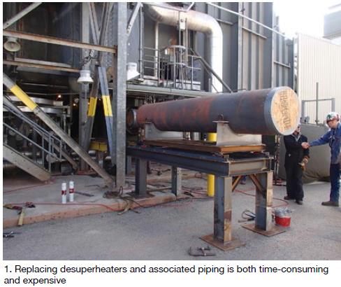
Additionally, thermal cycles on downstream piping can lead to cracking of the protective thermal sleeve, if installed, or the base metal. Inspections should be conducted every two years given the number of problems plants are experiencing. The old inspection recommendation was every five years. Replacing desuperheaters and associated piping is both time-consuming and expensive (Fig 1).
Stanley suggested that users track spray-valve open/close cycles using PI data and use that information for inspection and maintenance planning. If the number of cycles seems excessive, review steam-temperature control logic; don’t over control, he advised. An attendee said one of his spray valves has 10,000 cycles and no problems have been identified—yet. Stanley could not offer a rule-of-thumb regarding the number of cycles to plan an inspection program around.
The boiler engineer also suggested checking final steam-temperature set points at loads associated with problems and to make changes where appropriate. He offered the following advice:
- Reheater and HP superheater independently may have points where it makes good sense to keep the control valve at the minimum-open position during startups and operate at a slightly lower steam temperature.
- Confirm that spray-water control-valve trim design and size are correct for current service conditions. Is it possible to install new, lower “minimum-flow” valve trim? It can provide tighter control. But make sure the new trim allows sufficient water flow for other operating loads.
Attemperator overspray during startup was the next topic addressed by Stanley. It initiates the same type of damage described above for spray-water leakage. One cause of overspray, he said, is the need to maintain the recommended steam temperature to the steam turbine, which may be as low as 700F during the “soak” period. Another is the rapid and high spike in GT exhaust temperature characteristic of the 7FA at low load. A third cause may be an over-performing (defined as too much surface) superheater or reheater at low load.
With regard to the second point, Stanley pointed out that interstage desuperheaters (located between the primary and secondary superheaters) generally cannot control steam temperature to more than 100 to 150 deg F below the gas-turbine exhaust temperature. He added that steam leaving an interstage desuperheater should be 50 deg F over the saturation temperature, as a general rule, to minimize operational risk. This may be impossible at low loads for some HRSG designs at some turbine exhaust conditions, he conceded, but there are options to consider—including air attemperation at low load.
Before moving on to the next subject, Stanley pointed out that given a good interstage desuperheater arrangement, a good liner, and plenty of straight-run pipe before/after the attemperator, you probably could operate the desuperheater at 25 deg F above saturation.
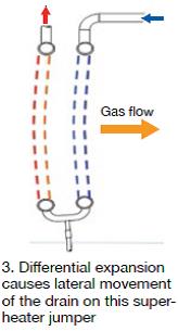
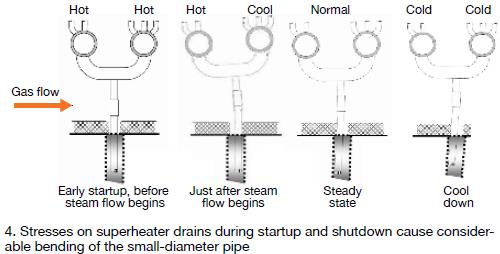
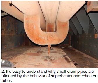
Fig 4 illustrates how the drains on superheater jumpers bend during different stages of startup and shutdown. Stanley provided several tips on how to avoid problems associated with drain-pipe stress. It all begins with a close inspection of the drains, he said. Next, upgrade floor penetration seals to allow sufficient lateral motion. This includes improving floor-liner flashing to avoid binding and lateral expansion interference. Plus, don’t forget to check tube-panel expansion guide supports for proper alignment, Stanley added: You don’t want drains serving as unintended guide points.Thermal expansion of superheaters and reheaters is an important consideration in any smart-start program. Very small drain pipes are affected by the behavior of superheater and reheater tubes (Fig 2). As Fig 3 shows, differential expansion amplifies lateral movement of the drain on this superheater jumper serving a top-supported superheater. High spray water flow to the interstage attemperator increases the risk of excessive lateral movement.
Stanley wrapped up this segment of his presentation with the suggestion that for some panel configurations, bent drain problems can be corrected by use of spring supports. They can reduce thermal stress on tubes and jumper pipes while also adjusting drain movements, he said.
Economizer thermal shock. Stanley explained how thermal shock occurs to economizers on startup: Operator expects drum swell and feedwater control valves are shut to prevent water flow. Economizer is stagnant and “soaks” to a higher temperature than normal. The feedwater control valve opens as drum level starts to drop and the incoming cold water shocks the economizer.
With tubes rigidly restrained at the top and bottom, high tensile stresses result when the economizer is shocked. Similar or worse shock can occur when adding water to an economizer during overnight shutdowns—such as when topping off the drums (generally not recommended).
Preventing thermal shock in economizers is relatively straight forward. Example: For LP economizers, recirculation pumps can be used to blend cool water with warm recirc water prior to entering the tubes. Simpler still is to avoid topping-off drums—especially during periods of peak back-end temperatures during nighttime shutdowns. It also is advisable, Stanley said, to start HP, IP, and LP feedwater flows in the range of 5% to 10% very early in the startup sequence. Use blowdown to manage drum levels.
An economizer upgrade is another option to mitigate thermal shock. For return-bend economizers, an upgrade of the tube support system may be all that’s necessary. Alternatively, you might consider a full or partial upgrade using HRST’s ShockMaster™.
Steam-drum manway sealing is an important consideration during any restart, particularly so when the startup follows an outage in which the drum door was opened. A couple of points to keep in mind:
- HP-drum gasket leaks can cause costly startup delays and may be life-threatening in the extreme.
- Platforms generally are narrow at the drum level and maintaining a safe distance between operators on rounds and the drum door can be challenging.
- Industry practice has encouraged retorquing of fasteners during ramp up to operating pressure. Stanley suggested that where this is still done, the practice should be re-thought because of the personnel danger involved.
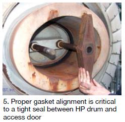
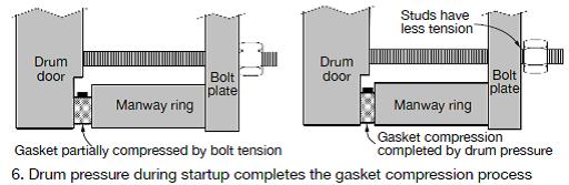
The boiler expert crawls in and out of steam drums on a regular basis and assured the less experienced in the room that aligning of the HP drum door, hinge, and manway is not a simple task (Fig 5). A typical drum-door configuration is shown in Fig 6. Note that drum pressure during startup completes the gasket compression process. Retorquing of door studs after pressurization and before the next startup often is required to maintain sealing force, but as noted in the last bullet point immediately above, hot retorquing has safety implications.
Develop careful gasket alignment and safe torqueing procedures.Stanley suggested the following smart-start action plan:
- Optimize drum-door hardware to reduce the safety risks associated with a steam leak.
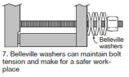
- Consider the Belleville washer arrangement shown in Fig 7 on drum studs.
- Install special hardware, available from HRST, to maintain accurate alignment of the gasket while closing the drum door.
The last portion of Stanley’s presentation concerned HRSG “startup time limiters.” Here’s what he had to say about them:
NFPA purge. Reduce startup time by up to several minutes by minimizing purge time. Purge credit often can be taken upon shutdown for GE E- and F-class frames. A triple-block and double-bleed valve arrangement is required in the gas lines. Absent on-staff engineering capability, engage a consultant to see if a purge credit would benefit your operation.
Drum level control. Fast starts make drum-level management more challenging, particularly in IP drums. Stanley suggested starting with a low drum level, using intermittent blowdown to dump drum water if necessary, and tuning drum-level control logic to minimize operator intervention. In general, he said, fast start works better with automatic control, particularly with today’s small operating staffs.
Steam temperature matching. The gas-turbine startup rate may be restricted because the temperature of the steam exiting the HRSG exceeds that required for steam-turbine warm-up. If the attemperator cannot provide the necessary temperature control, a GT hold likely would be required.
Corrective action might include installation of a superheater bypass that allows mixing of HP-drum steam with superheated steam to reduce the temperature of steam flowing to the turbine. Alternatively, an additional desuperheater could be installed downstream of the secondary superheater. Electric blankets to keep the steam-turbine casing warm is another option. None of the three potential options is without cost, risk, and limitations.
HP drum stress. The HP drum is at risk of fatigue damage when pressure changes quickly and a temperature gradient occurs through the vessel wall. Specifically, the inside of the drum rapidly tracks the saturation temperature; temperature of the drum’s outside wall lags as heat slowly flows through the thick shell. If the temperature differential gets too large, resulting stresses can initiate cracks at discontinuities—such as large nozzles. Nozzle weld design is a big factor in this.
Minimize the risk of drum cracks by controlling startup and shutdown temperature ramp rates to those recommended by the OEM. Program the DCS to alarm if ramp rates are exceeded. If the drum ramp rate is limiting your ability to start faster, have the OEM or a qualified consultant analyze your HRSG and steam system to see if it’s possible to shave a few minutes off your starts. Consider a drum-stress monitoring system to measure temperature differentials at critical locations and control ramp rates to acceptable stress levels.
Other options include installing an auxiliary boiler for steam sparging, replacing partial-penetration nozzle welds with full-penetration welds, and controlling the HP drum-pressure ramp independently of the GT startup rate. The last requires somewhere for the steam to go—such as a full-capacity vent or bypass. Use of sky vents can be expensive, as can redesign of the condenser to handle the additional high-energy steam flow.
Fuel-gas preheater. Fuel gas typically must be at 300F-350F for NOx control and the gas turbine is load-limited until that condition is achieved. Water from the IP steam drum often is the heat source, but the time it takes to reach the nominal 275-psig drum pressure required may be slowing your startup. If that’s the case, consider using as the heat source HP economizer water or IP economizer water (via a control valve between the IP economizer and drum). CCJ