Seasoned owner/operator personnel tackle the biggest industry issues

The depth and breadth of experience represented by 11 owner/operator presentations at the 2023 7F Users Group Conference can be summed up like this:
- Chronologically, they represent machines dating back to the original F-class gas turbines (GT) off of the test stands in 1988.
- Numerically, these users are responsible for at least 150 7F units, maybe closer to 200.
The presenters themselves are some of the most seasoned experts in GT operations and maintenance in the nation; many are names familiar to the GT user group community. Topically, the presentations can be grouped as follows:
- Two deep dives into specific compressor issues.
- Two deep dives into specific combustor issues.
- One addressing myriad control-system issues.
- One discussing the exhaust end.
- One on turbine-bucket creep failure.
- A primer on the latest 7F combustor system (the DLN 2.6+).
- One on a fuel-gas stop/speed ratio valve actuator.
- Two “system” presentations on lifecycle management and R&D aspects.
At the risk of sounding like a late-night Ronco commercial, don’t delay. After reading the high-level summaries presented here, go to www.powerusers.org and look at the slides, available for viewing to user members of Power Users (user non-members will have to apply and be approved by the leadership). If you are responsible for 7Fs in your fleet, the editors believe you’ll be glad you did. Don’t forget to register for the 2024 annual conference this May.
Beware shrouded S17 blades
An owner/operator representative with 15 7F units dating back more than 30 years described the company’s strategy for replacing, upgrading, and enhancing the compressors in the fleet and subsequent operating experience. The program began in 2009 and the last of the simple-cycle units is expected to be completed in 2025.
Others with or eyeing shrouded contoured S17 blades as an enhancement, take note. The presenter’s conclusion is succinct and blunt: The enhancements went smoothly and performed well except for the shrouded S17s. Two units experienced pressure-side root rubs in the S17s, which subsequently had to be “surgically removed and replaced.”
Execution lessons learned include making sure to use the right gages (taper versus feeler) in the right places when collecting all the necessary data, walking down the rotor transport route as each site is different, and managing expectations on the condition of a “just in time” rotor in layup.
Addressing T-fairing distress
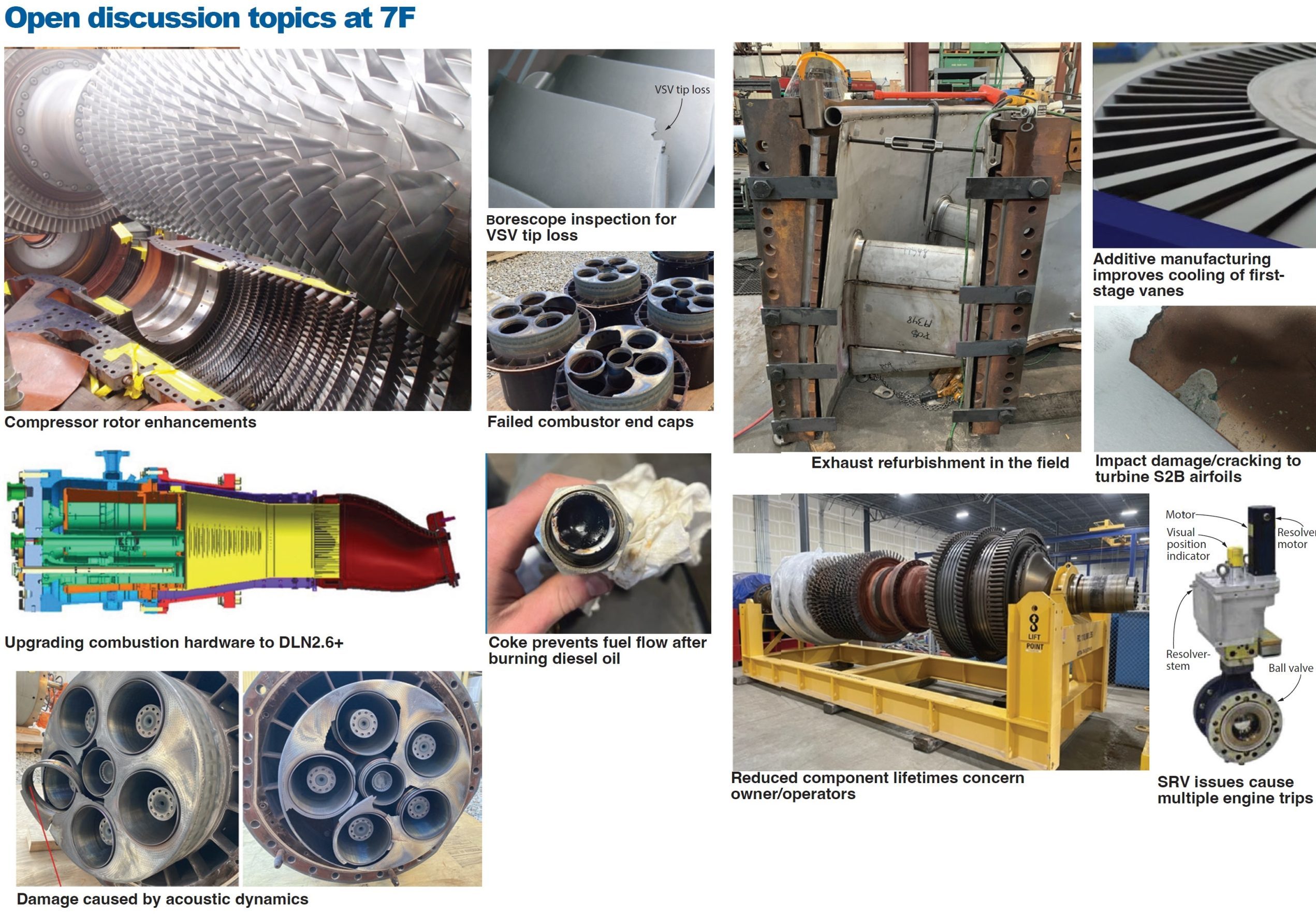
Described in TIL-2212, T-fairing is a circumferentially loaded platform on the compressor rotor that has an inner flow path between R1 and R2 and R2 and R3 under the tips of variable stator vanes (VSV) 1 and 2. An expert for an owner/operator with a fleet of over 50 7F machines noted the general concerns: VSV tip rubs and liberated material, circumferential gaps and T-fairing shingling leading to rotor imbalance, compressor blade platform damage, and rotor/wheel dovetail slot wear.
The presenter noted that the three TIL revisions to date, the most recent in August 2022, express a progressive level of urgency to address this issue. Recommendations to mitigate the original T-fairing operational risk include:
- Borescope inspection (BI) as specified in the TIL to inspect for VSV tip loss, excessive gaps, and wear/rubs.
- Monitor units even more closely if equivalent turning gear (ETG) hours are greater than 15,000.
- Monitor T1 and T2 seismic vibrations; alarm at 0.50 in./sec, runback at 0.82 in./sec, and trip at 1.00 in./sec.
- If T1/T2 alarm is triggered via step change, inspect at next opportunity and suspect T-fairing shingling or hard rub.
When replacing T-fairing, ensure lockers did not migrate or disengage per TIL-2391: Torque-check exposed lockers (four per stage) in R3-R6, and BI R7-R14.
Results with DLN2.6+ with AFS/OBB
An owner/operator with 32 7F machines in its fleet reported on turndown performance after retrofitting four FA.04 units at one site, between 2020 and 2022, with dry low NOₓ (DLN) 2.6+ combustion hardware along with axial fuel staging (AFS) and overboard bleed (OBB).
While all of the machines met or exceeded their performance guarantees (numerous graphs provided), the user did underscore effusion-plate cracking found during a spring 2023 BI after 25,000 fired hours affecting 14 of 56 combustor cans. The OEM plans to modify the area with thermal barrier coating (TBC) per TIL-2292 at the next hot-gas-path inspection (HGPI).
Separately, the speaker noted that limited tuning capability on the part of the OEM’s service team for this new technology led to 12 schedule modifications. Up to 12 days were required to tune each 2 × 1 block.
Other lessons learned: Ensure outside instrumentation is heat-traced (a compressor discharge pressure transmitter for the AFS froze up and kicked out AFS operation); ensure that the SSO (safety shutoff) valve blank is removed (caused a two-day delay getting back online); check for looseness in the AFS damper (one-day delay for inspection and tack welding); and have a backup emissions analyzer available.
Combustor end-cap failure RCA
You’ll have to check out the slides to experience the “perfect storm” which led to a catastrophic failure in 2023 of combustor end caps following a flange-to-flange replacement in 2022 of an unflared 7FA.01 (with 181,000 fired hours) to a flared 7FA.04 with DLN2.6+ and AFS.
Some of the elements in the storm were the result of what the presenter called “downgrades” from the replacement (as opposed to “upgrades”)—such as switching the control system from Ovation to Mark VIe and changing the tuning option from manual to the OEM’s Autotune MX.
As recently as October 2022, a BI turned up no significant findings on the unit. The presenter’s frustrations with the OEM are also clear in the slides, especially when poking fun at the OEM’s euphemisms and obfuscating language. Reportedly, the OEM was essentially no help during the short-term recovery of the unit after this catastrophic failure; site personnel had to figure stuff out on their own. As for a long-term solution, a new TIL to fix the bugs in Autotune, which disregarded the high dynamics (a key part of the “storm”), wouldn’t be available until fall 2023.
Cornucopia of controls issues
One of the industry’s leading user experts on GT controls reviewed myriad issues, some associated with TILs, but also controls associated with emergency bearing-oil pumps and lube-oil seal-pump starter failures; liquid-fuel purge systems; non-optical flame detectors; high turbine-compartment temperatures; compressor-bleed-valve drain lines; modified exhaust-temperature-spread monitoring in EMS2100, Mark VIe TTUR card (associated with the primary trip terminal board) failure associated with generator synchronizing out of phase; and compressor discharge temperatures.
Robust exhaust replacement
These slides offer a pictorial view and chronology of an exhaust-system replacement at a 2 × 1 combined-cycle facility. Drivers for the project included exhaust liner cracks, flex-seal failures, horizontal joint separation, high exhaust-frame-blower amperage readings, and frequent exhaust-frame-blower motor change-outs over the five years before the project. Solution was to replace the back end with the OEM’s “Robust Exhaust Upgrade.”
Post-installation photos are included of both units, one after 1500 hours and 15 starts, and the other after 19,000 hours and 70 starts. Graphs show that the blower motors are operating generally below the threshold of high amperage. One caution: Be sure to thoroughly check that no insulation is missing if you are planning one of these replacement/upgrades.
Fleet R&D activities
A representative from the Electric Power Research Institute (EPRI) identified and expounded upon areas where R&D is being conducted on behalf of all EPRI member fleet owner/operators. Examples offered of R&D projects with “proven value” include the following:
- Using EPRI’s digital-twin technology for managing regular maintenance activities and enhancing GT dispatch.
- Balancing operational risks from power augmentation with market opportunities to sell additional megawatts during high-price periods.
- Providing guidance on overall quality control and assurance during major planned HGP outage activities.
- Applying additive manufacturing to enhance first-stage vane cooling and overall engine performance.
- Applying process component resonance (PCR) testing to validate repairability of second-stage turbine blades.
- Demonstrating 20% to 40% hydrogen blending in LM6000 and 501G units.
Second-stage-bucket creep failure
A metallurgist for one of the largest fleet owners in the US analyzed the March 2022 failure of 7FA.03 second-stage buckets in a combined-cycle unit with commercial online date (COD) of 2007. The failure occurred after a shutdown on abnormal vibration following 22,300 hours and 95 starts since the last HGPI in November 2018. A subsequent BI showed S3B material liberation but no evidence of foreign object damage.
Further inspection revealed SB2 degradation on 92 10-hole (cooling) blades supplied by a third party, including airfoil impact damage/cracking on 14 blades, shroud damage on 89 blades, missing leading-edge shrouds on four blades, and shroud cracking on 85 blades. Regarding the SB3 row, all blades lost shroud area, but there was no noticeable root damage or fractured, heavy impact damage.
Fourteen of the third-party S2B blades were compared to original OEM blades and it turned out that airfoil and tip shroud geometries were not placed in the same position and bucket tips were lifted significantly. Six S3B blades similarly compared were consistent except one blade showed localized differences because of bending from impact damage.
Overall, there was “strong evidence” of creep damage in the S2B shrouds and no noticeable evidence of creep damage in the S3B shrouds. Site-to-site comparisons of operating data revealed that the failed unit runs relatively hotter than the other 7F.03s in the user’s fleet—similar to Dot 04s in fact, based on historical exhaust temperature data. Long-term solution was to replace the S2B rows of blades with ones of OEM design.
Component lifecycle management
While these slides act mostly as prompts for a facilitated discussion with the audience, they do offer insights into what is keeping this owner/operator GT expert up at night. In particular, as components approach end of original expected life, there is competition for supply of new parts and shop refurbishment space.
Meanwhile, additional lifecycle issues continue to be discovered, putting additional pressure on fleet owner/operators. Another complicating factor: OEM TILs and bulletins go through many revisions. The presenter cited GER 3620, now on revision P (2021).
If you and your team are trying to set an overall fleet life and refurbishment strategy, this likely is a presentation worthwhile reviewing.
Fuel-gas SRV actuator issue
At this 7FA.05 site, the safety/speed ratio valve (SRV) (with digital valve positioner DVP) tripped on a fault, then the same SRV tripped in the companion unit. The first unit then tripped twice, after the SRV was repaired, because of relay issues. There was actuator gear damage, for which the OEM is performing an RCA. The P2 cavity pressure transmitter reading was fluctuating rapidly, but once the input filtering was changed, the fluctuations were greatly reduced.
Although the site-specific details (including many control system diagrams, jargon, and acronyms) are available in the slides, the action items are probably of most use to readers:
- Have full SRV spares available, including the DVP, onsite and back-up the DVP software.
- Make sure spare relays and contacts are available and test new relays in the shop before stocking them in the warehouse.
- Be familiar with Woodward diagnostic tools and software.
- Lubricate actuator and stroke valves periodically.
- Monitor deviation between valve command and feedback.
- Review alarming strategy and configure additional signals if necessary.
- Review P2-cavity pressure-transmitter signal input filters and adjust as necessary.
DLN2.6 system tuning
This user presentation with over 50 slides is essentially a primer on the DLN2.6 combustion system. Broad topics covered include an introduction to fire and flames, fuel gas system and combustion components, control variables and terminology, DLN modes and startup sequence, acoustic dynamics, emissions, DLN2.6 tuning, and overview of DLN2.6+ and AFS.


