Metal temperature is, perhaps, the variable most affecting the service lives of superheaters and reheaters. Long-term overheating of these components can result in failures necessitating multi-million-dollar repairs, based on the experience of Bryan Craig, PE, and his colleagues at HRST Inc. There is an upward trend for overheating failures in the industry, and many HRSGs are approaching the time in their respective lifecycles when this is becoming a significant risk.
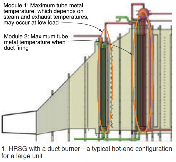
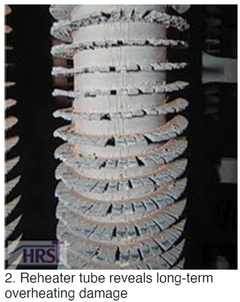 Fig 1 shows a typical configuration of a large HRSG with a duct burner. In HRSGs with duct burners, maximum tube metal temperatures in Module 2 occur when duct firing. An increase in the operating metal temperature of 15 to 20 deg F can reduce equipment life by half in some instances.
The overwhelming majority of superheater and reheater overheating failures seen to date by HRST engineers have been downstream of duct burners (Fig 2). Poor exhaust-gas and/or fuel-gas flow distribution at the duct burner can lead to local areas that are fuel-rich, resulting in long flames and local overheating in the downstream tube bundles.
Here are two scenarios:
Uniform fuel-gas flow distribution, non-uniform exhaust-gas flow distribution.
Turbine exhaust gas (TEG) is the “air” source for an HRSG duct burner. If the fuel gas is distributed uniformly throughout the burner elements, but the exhaust gas flow is non-uniform, then the areas with higher-than-average exhaust-gas velocities will have a high air/fuel ratio, and areas with lower-than-average exhaust-gas velocities will have a low air/fuel ratio. A low air/fuel ratio means fuel-rich. Thus, areas with lower-than-average TEG velocities will be fuel-rich and have longer-than-average flames.
Non-uniform fuel-gas distribution, uniform TEG flow distribution.
This is straightforward. If there’s uniform distribution of TEG flow to the duct burner, then the areas that receive higher-than-average fuel flow will be fuel rich, comparatively, and will have longer flames.
In reality, of course, neither the fuel flow nor the TEG flow to a duct burner is perfectly uniform. Still, it helps to think of the two effects separately.
TEG velocity profile. Turbine exhaust enters the HRSG at high velocity, at a low elevation. The momentum of TEG flow entering the HRSG causes its velocity to be higher at the bottom of the duct burner and lower at the top. This can be corrected by installing a flow-distribution device—such as a perforated plate.
If there are multiple rows of HP superheater and reheater tubes upstream of the duct burner, the flow resistance of these also can help to even out the TEG flow profile at the duct-burner plane. Even so, it typically is not perfectly uniform, as Fig 3 shows.
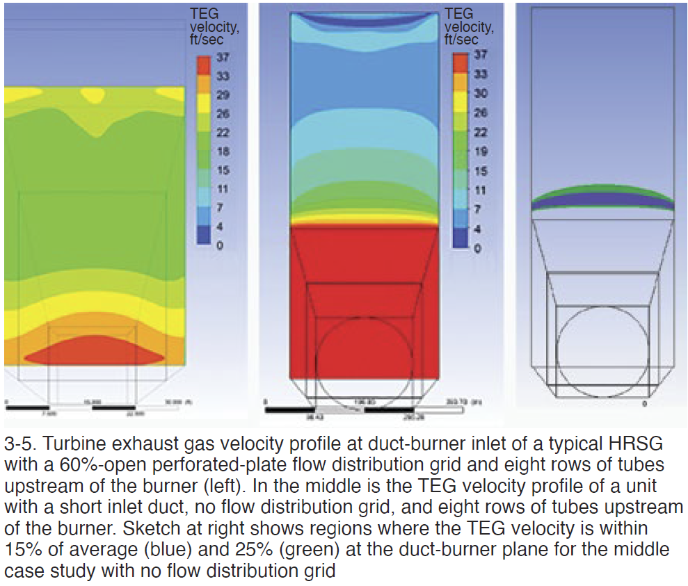
With this TEG flow profile, and assuming fuel flow is distributed equally to each duct-burner element and uniformly across the elements, you can expect a higher-than-average temperature and longer flames downstream of the HRSG at the top of the unit, and a lower-than-average downstream temperature at the bottom of the HRSG—based on the relative air/fuel ratios in the different zones.
Fig 4 presents the velocity profile for another HRSG, on the same scale as that described in Fig 3, but one with no flow distribution grid and a very short inlet duct. The TEG velocity at the bottom of the HRSG is much higher than average and the TEG velocity at the top of the unit is much lower than average. There is only a small zone with a TEG velocity close to the average value across the plane, as Fig 5 indicates.
Fuel flow profile. Now, let’s look at fuel flow. Fuel enters the HRSG at a much lower temperature (40F is typical) than the nominal 1000F TEG temperature at the duct-burner inlet. Thus, the fuel heats up as it flows along the duct-burner element. Heat-transfer calculations made by HRST engineers predict the fuel temperature curve in Fig 6 for a typical duct burner.
Most duct burners inspected by HRST personnel have uniformly distributed, equal-size openings (a/k/a nozzles) in the burner runners. With this design, a higher fuel flow per nozzle is expected at the inlet end of the runner where the fuel is cooler than it is at the far end. The duct-burner fuel-flow profile in Fig 7 is based on the fuel-temperature profile from Fig 6.
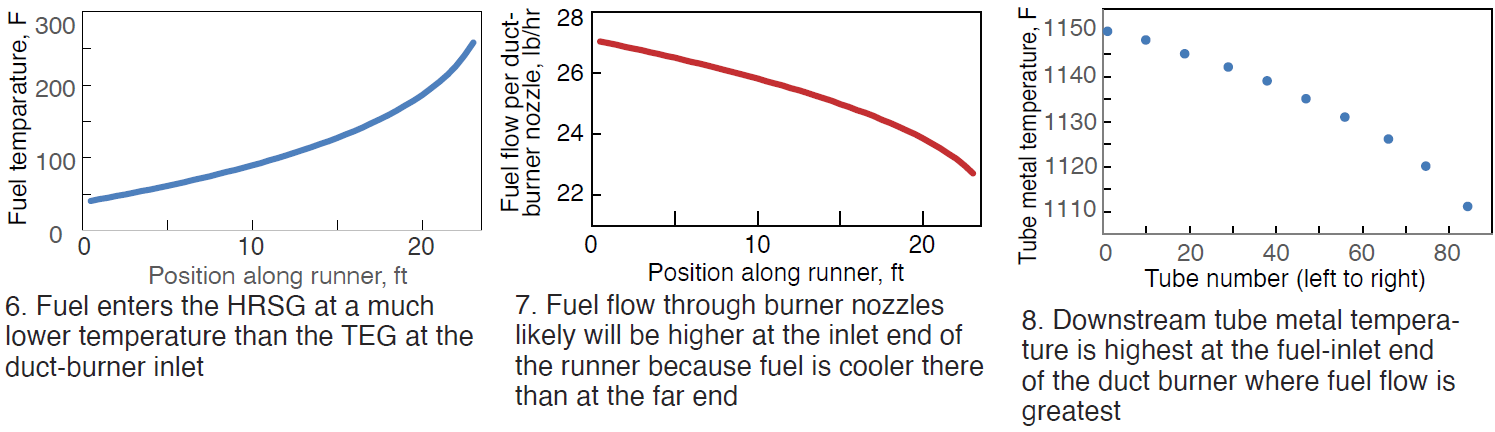
With this fuel profile, one would expect the downstream gas temperature to be higher, and flame length longer, on the fuel inlet side of the duct burner; and lower/shorter on the far side.
If you calculate the downstream tube-metal-temperature variation driven only by the effect of left-to-right fuel-flow distribution along the length of the duct-burner elements, the difference from the left side to the right side of the HRSG is nearly 40 deg F, as illustrated in Fig 8. This is substantial considering that a 15- to 20-deg-F difference in tube metal temperature can correlate to a factor of two in creep life!
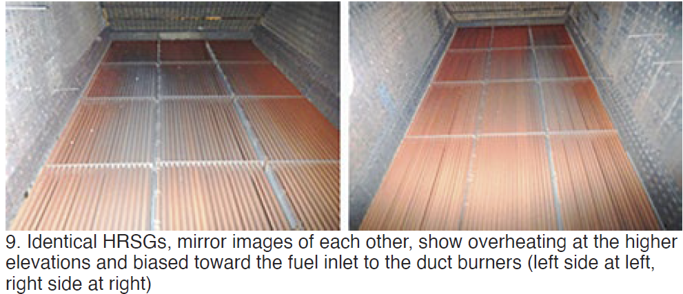
Combined effects of fuel and exhaust-gas flow distribution. The photos in Fig 9 are from a plant with two identical HRSGs, except that they are mirrored. There are no flow-distribution grids in these units. The downstream tubes in both HRSGs show indications of overheating at the higher elevations, plus a bias toward the fuel-supply side.
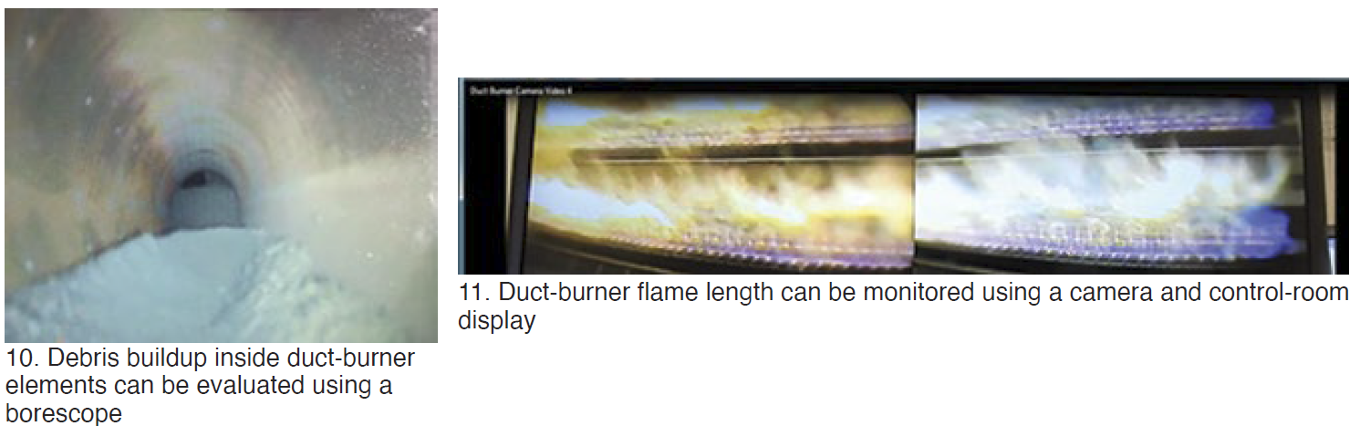
It gets worse, in some cases. Duct-burner nozzles sometimes become plugged with debris (Fig 10). In HRST’s experience, nozzle plugging is most prevalent at the far end of the burner elements (opposite the fuel supply).
Plugging can significantly exacerbate fuel-flow maldistribution, causing a far greater left/right temperature imbalance downstream of the burner than the fuel-temperature-driven imbalance described above. HRST engineers have seen instances of very large left/right fuel flow imbalances caused by nozzle plugging. Some of these have resulted in HP superheater tube failures immediately downstream of the duct burner.
 Recommendation: Use existing view ports to visually observe the flames for length and shape when the HRSG is operating and the duct burners are at maximum fire. Flames should be independent and horizontal. A rule of thumb: Flame should extend only one-half to two-thirds of the way down the firing duct. If flames come within 3 to 4 ft of tubes, that’s probably too close. Flames should never contact the tubes! If long flames occur, it is likely because of a problem with either exhaust-gas or fuel flow distribution—perhaps both.
A duct-burner camera is an alternative to using view ports to observe flame length during operation (Fig 11). One or more cameras can be installed inside the firing duct and provide a real-time view of the duct-burner flames to the control room operator.
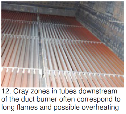
During offline inspections, make note of, and photograph, any color variations in the tube bundle downstream of the duct burner. Gray zones in tubes downstream of the duct burner often correspond to long flames and possible overheating (Fig 12).