With the 2024 HRSG Forum fast approaching in June, have a look at the breadth of topics and discussion points covered at last year’s event during the solutions provider presentations, featured here, and all the other components of the conference. The 2023 HRSG Forum event in Atlanta, the organization’s first physical meeting since the Covid interruption, established the current four-day in-person format, encouraging all attendees to participate in the following:
- Cycle Chemistry Workshop—Film-forming substances
- Materials Workshop—Welding and metallurgy
- General Session presentations by Users
- General Session presentations by service providers
- EPRI Technology Transfer Workshop
Vent silencer design, inspection
Samir Baydoun and Tucker York, SVI Bremco, presented HRSG vent-silencer safety inspections and design, focusing on the safe and quiet discharge of high-pressure steam. Most silencers are installed at high elevations downstream of steam-drum relief valves, HP/RH safety valves, and startup ventilation. They can also be installed on blowdown tanks and deaerators. Their primary purpose is to meet site-permitted noise limits.
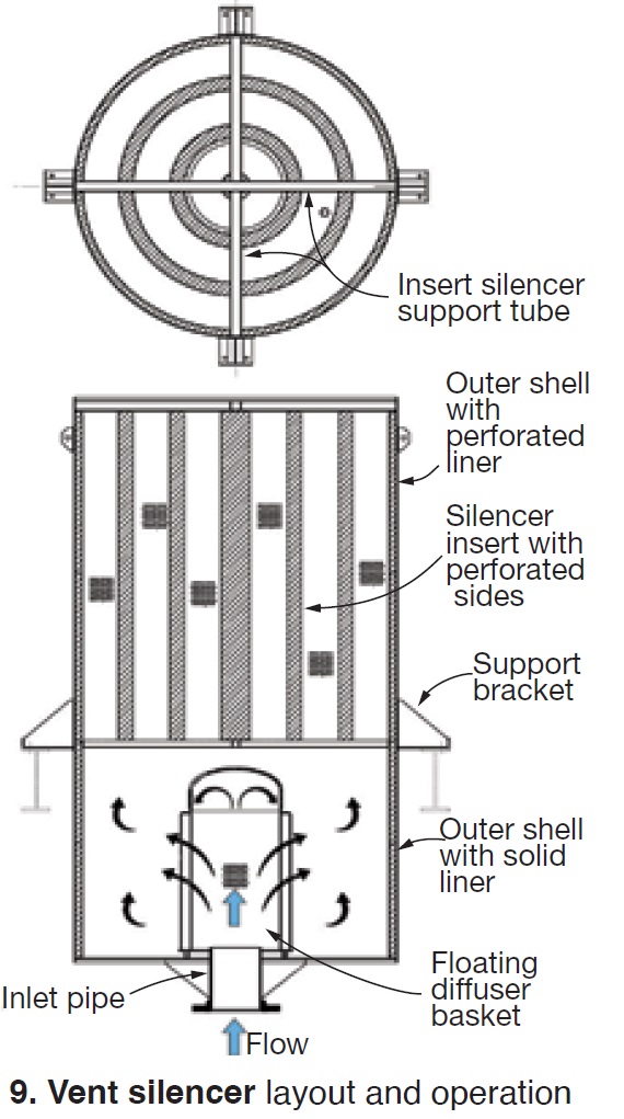 Main vent-silencer components are: diffuser assembly with inlet pipe, silencer shell with or without liner, and silencer inserts (Fig 9).
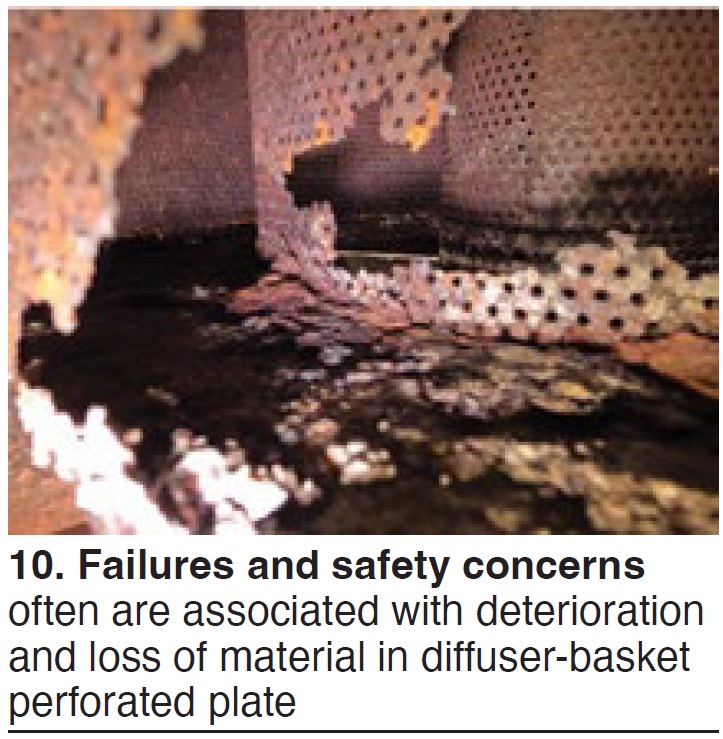
Presenters covered common failure and safety concerns, usually caused by deterioration of the silencer perforated liner or diffuser basket and loss of acoustical insulation (Fig 10). The result is loss of aerodynamics and acoustical performance, but a major safety issue occurs when parts of the liner separate and eject out of the silencer.
Visual inspection methods are presented in an eight-point summary covering corrosion, missing bolts, cracking, weld damage, and improper draining. Go-Pro cameras can be used to check baffle sheets, frames, and supports. Cameras can also check various welds and diffuser-cap conditions.
Root causes of damage could be inherent in design or in selection of materials, welding processes, corrosion, and water collected at the bottom of the silencer (clogged drains). Thermal fatigue can also occur because of temperature, number of cycles, and other operating conditions—including backpressure. Thus, routine inspection is critical.
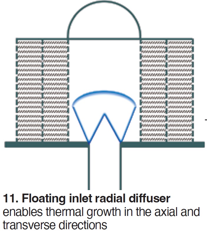
Details of an SVI Dynamics vent silencer are provided. It uses an inlet radial diffuser with either a one-, two-, or three-wall arrangement (Fig 11). The floating diffuser replaces common metal bells and enables thermal growth in the axial and transverse directions. The lower plenum section is an expansion chamber for radial dispersion of flow, and promotes uniform flow transition to the absorptive upper stage. The upper stage is designed in either concentric-baffle configuration, tubular array, bar array, or parallel-baffle arrangement. Variations are in thickness, spacing and active length to further dissipate acoustic energy (Fig 12). The diffuser basket is critical to redistribute the energy radially.
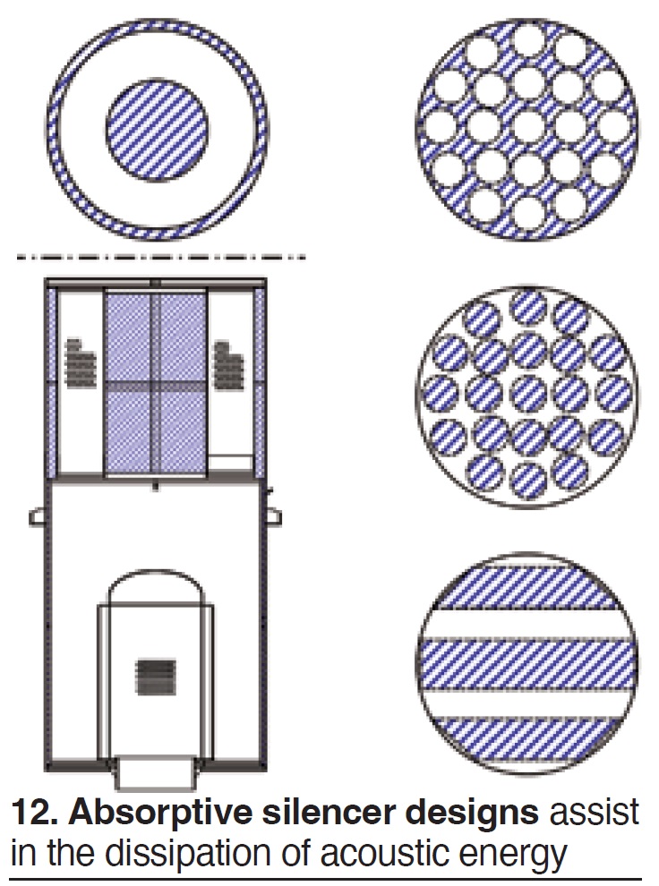
The silencer works by acoustically shifting from broadband to middle-to-high-range frequencies.
Discussions included design details and welding to ASME specifications, and the benefits of detailed metallurgical exams of failed materials.
Tube repair innovation
Tuff Tube Transition (TTT) offered Innovative HRSG tube repairs, specifically a sleeve-type connection that eliminates open-root butt welds, does not require back purge, and eliminates the need for NDT/RT. This provides a “faster and more reliable joint alignment,” said Marshall Hicks of Viking Vessel Services/TTT.
As an overview offered by Hicks:
- The thicker material of the sleeve-type TTT increases the connection stiffness and decreases stresses (virtually eliminates fatigue cracking in tube-to-header joints).
- The reduction of stresses corresponds to a decrease in the weld connection stresses.
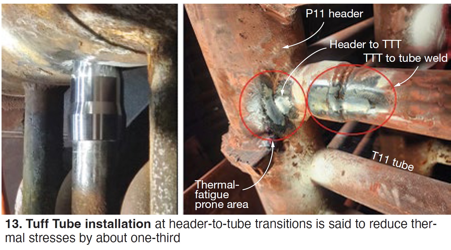
- The 30% reduction in thermal stresses claimed is said to increase connection life and reduce the number of failures, plus increase service life by 50% to 75%.
The Tuff Tube Transition, developed by Viking, was first used at Calpine Freestone Energy Center in Fairfield, Tex. TTT was applied on sections with P11 header and T11 tubes in an HRSG that had been in service for 20 years (Fig 13). These purgeless sleeves are made of T22 (2.25 Cr-1 Mo).
After two years of service and 102 cycles, PMI Specialists Inc, a metallurgical services firm, was asked to evaluate the condition of the welds. Finite-element-analysis results were discussed.
Table compares TTT and conventional methods of tube repair.
Comparing method of boiler-tube repair |
|
Tuff Tube Transition |
Conventional |
|
|
Tuff Tube Transition is US made and warranted, and offers full packages for HP, IP, and LP sections. When asked if TTT applied to both steam-touched and water-touched service, the answer was “both.”
The discussion period dove further into experience. There are currently no reported issues with TTT installed in nine HRSGs. Questions included any resulting flow restrictions, but to date there have been no negative effects. Further results and discussions are anticipated at HRSG Forum 2024.
Detecting spray-water leakage
Denis Funk, Flexim, discussed Ultrasonic detection of spray-water leakage to find leaks and prevent attemperator steam pipe and superheater/reheater tube damage.
This was a case study from 2020, when a major CCGT operator had issues with HP and RH steam tube damage. Several cracks also had been discovered in attemperator spray liners.
The suspected root cause was HP attemperator spray block valve leak-by, with quenching of the liner and tubes during low load. First response was to diagnose leaking by continuously monitoring conditions using existing instrumentation, with these problems:
- Differential flow meters are limited in turndown and low-flow resolution.
- Comparison of upstream and downstream thermocouples did not show sufficient accuracy for low-flowing leak-by.
- Acoustic monitors were not providing flow values, just noise signatures.
The operator then consulted with EPRI and Bob Anderson, Competitive Power Resources.
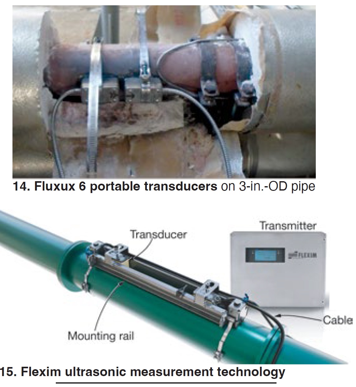
Testing involved Fluxus 6 series portable equipment with transducers for extended temperature range at three different locations on the HP and RH spray lines. These are non-invasive ultrasonic flow meters (Fig 14).
Measurements were taken during valve opening and when fully closed (for leakage detection). Testing showed that the ultrasonic meter and the calculated flow (heat-balance equations) matched very closely. However, the differential-pressure-based flow meter was not able to capture the flow rate precisely, especially during low loads.
Funk noted that “During low loads, leakage can cause the most damage because the spray is not completely evaporating.”
Two ultrasonic transducers (Fig 15) are mounted with a defined distance onto the pipe. By sending sound signals alternating with and against the flow, a transit time difference can be measured. This corresponds to the flow velocity, and calculation of volume flow and mass flow.
The equipment features no moving parts, no pipe penetrations, high repeatability, and is factory calibrated. Applications include natural gas, boiler feedwater, blowdowns, compressed air, cooling water, hydrogen cooling, and steam.
An interesting question followed: Can this distinguish between water and steam? The answer was “yes,” using diagnostics.
After various utilities reported successful use of this equipment during discussions, Bob Anderson carried support a bit further, saying: “Once you know the fluid, pipe OD, wall thickness, materials, etc. and enter this into the meter, it automatically gives you the transducer spacing and calibrates the system. The meter communicates with the transducer to acquire the specific calibration curves. Fluid temperature is also an important variable, but temperature elements in the transducer automatically provide this as well.”
One strong supporting comment came from Duke’s Eugene Eagle: “We have installed permanent Flexim meters on every Carolina unit’s HP and RH attemperators. We are looking to install them on the rest of the fleet.”
Silent sentinels
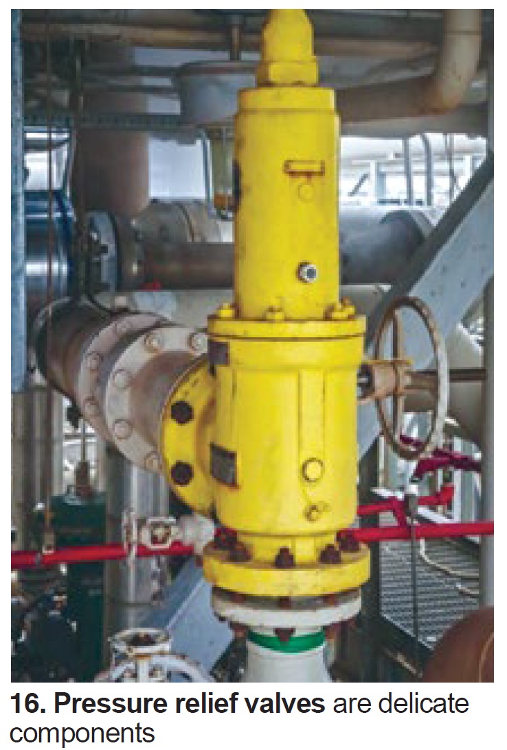
Kurt Bedar, NDE/PRD Consulting, offered a Pressure/safety relief valve maintenance program. “Pressure relief valves,” he began, “are one of the most ignored parts of the plant. They are the silent sentinels for safety.”
“Relief valves are often handled and stored like pipe fittings, but need to be treated as delicate instruments,” he said (Fig 16).
 Bedar stressed, “Perhaps no one valve plays a more critical role in preventing industrial accidents than the pressure relief valve.” Sometimes referred to as a safety or safety relief valve, it helps mitigate industrial accidents caused by the over-pressurization of boilers and pressure vessels.”
The three main parts of the valve are nozzle, disc, and spring. “Pressurized steam enters through the nozzle and is then threaded to the boiler. The disc is the lid to the nozzle, which opens or closes depending on the pressure coming from the boiler. The spring is the pressure controller,” he explained.
Common problems are a lack of testing and improper original specification. The former leads to reduced relieving capacity, leaking and shimmering, and improper repairs attributed to workmanship or failure to identify and correct problems. Also, said Bedar, “Replacement parts should be OEM only, and technicians must be certified.”
His conclusion: “It is essential that each PRV owner, in cooperation with an approved PRV service provider, establish an effective quality-control system to ensure that valves tested and repaired have been returned to conditions equivalent to the standards for new valves. By combining the use of competent repair personnel with an effective quality control system and conducting repairs in accordance with the provisions of the National Board VR Stamp certification program, a pressure relief valve tested or repaired will perform as expected when needed.”
Aging HRSGs
Mark Stockman, United Dynamics Advanced Technologies Corp (UDC), discussed NDE techniques for an aging HRSG fleet.
Stockman began with some generalized, conservative observations:
- Retirement age for HRSGs was often assumed (when installed) at 25 years for a baseload unit.
- Baseload was defined as four cold starts, 52 warm starts (weekend shutdowns) and several eight-hour-shutdown hot starts per year.
- The big buildout was in the early 2000s. Those units are getting close to end of life.
But some coal plants bult in the 1950s are still operating, exceeding 50 years. So do we need to get more life out of the HRSGs? “If so,” he suggested, “we have to focus on the life extension of installed units. This means thorough condition assessments.”
He offered some building blocks for life assessment and life extension:
- Review PI data and focus on overstressed components.
- Know that many problems are not visible from a standard inspection.
- Dig deeper using NDE techniques to determine where the next failure might occur.
Example: Use PI data to trend HP superheater outlet temperatures downstream of the duct burner, the temperature before attemperation. Look for temperature excursions. This is a target for NDE to determine the extent of damage. It also helps with root-cause analysis.
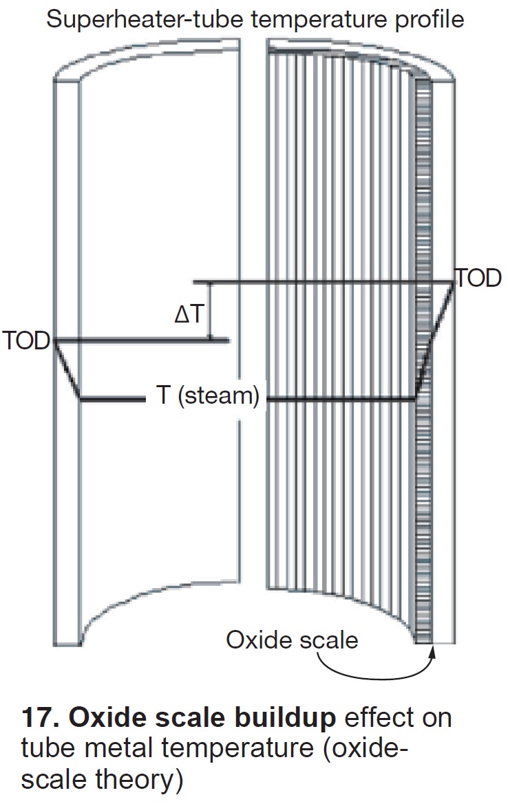
He offered other examples, then focused on HP, SH, and RH overheating, looking at tube-internal oxide scale and detection by NDE.
He described an oxide-scale theory in which 1 mil of scale equates to a tube OD temperature increase of 2 deg F. (Dooley later commented that this might be 4 deg F.) See Fig 17.For oxide-scale thickness of 0.01 to 0.03 in., this means a temperature increase of from 20 to 60 deg F.
Explaining further: “The primary failure mechanism in steam-carrying SH/RHs at temperatures above 900F is stress rupture. Primary contributors are temperature, stress, and time. Stress and temperature increase with time,” Stockman explained.
He then looked at tube-to-header welds for OD-propagated cracking, using magnetic particle testing on superheaters, reheaters, and HP economizers. Other areas shown were P91 drain and steam-drum nozzles.
Phased array, he said, is used primarily for ID-initiated cracking (tube-to-header welds, etc), for economizers, and drains in particular (Fig 18). He then reviewed ultrasonic thickness testing on elbows, economizers, and balance-of-plant areas.
Turning to drones Stockman looked at pipe supports and other areas not accessible from platforms, scaffolding or grade.
He then turned to metallographic replication to analyze piping components without removing samples. Videoscope inspections were next, looking at evaporator tubes, attemperator downstream piping and drums. Stockman ended with under-insulation corrosion, which he called “too often neglected.”