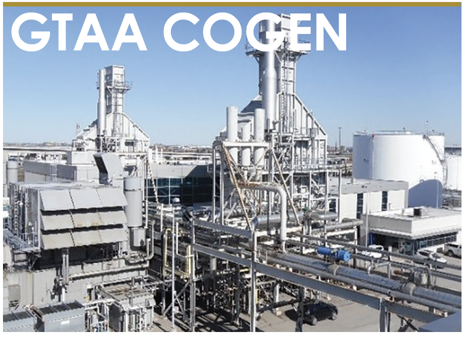
GTAA Cogen Plant
Owned by Greater Toronto Airport Authority Operated by SNC Lavalin O&M
117-MW, gas-fired, combined-cycle cogeneration facility located in Mississauga, Ont, Canada
Plant manager: Socrates Furtado
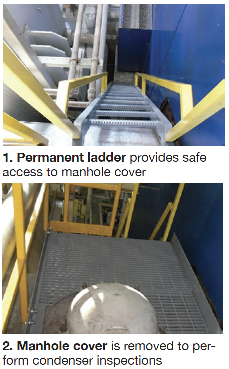 Challenge. The plant’s Siemens steam turbine has an inline condenser with a nominal 20-in.-diam bolted manhole on top for inspection purposes. The approach to this manhole is restricted by condensate and process-steam pipes. The manhole cover, at a height of about 13 ft and weighing about 30 lb, must be open when inspecting the condenser. This normally is done twice annually during the planned shutdowns, if not for emergency work on control valves in that area, which need occasional maintenance.
Plant staff used to approach this area with the help of ladders and fall-arrest and secure the fall- arrest at non-designated securing points. It was a challenge to work in the area with restricted body movement and most of the times posed a safety concern, especially while handling tools.
Solution. Install a permanent access ladder to this area (Fig 1). The intricate access dictated that the ladder be designed and fabricated in sections. Dimensional drawings were made by plant staff and provided to a contractor for certification and manufacture. Installation was completed with the contractor’s help. It was not an easy fit because of the various obstructions at the location of interest.
Results. The modification enables safe access to the area to open the manhole cover (Fig 2) for periodic condenser inspections and to inspect control valves when the plant is running. The platform, and railings around the manhole cover, provide safe working conditions both on top of the condenser and to anchor the fall arrests of personnel going down into the condenser for inspection.
Project participants:
Socrates Furtado, plant manager
John Power, operator
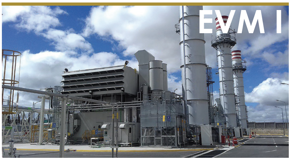
Energía del Valle de Mexico l
Owned by EVM Energia SAPI de CV Operated by NAES Corp
100-MW, gas-fired, three simple-cycle LM6000PF gas turbines located near Mexico City
Plant manager: Javier Badillo
Challenge. EVM l was initially planned as a peaker plant but growing electric consumption forced operation 24/7 during months of high demand. This required that lubrication of rotating equipment be conducted more frequently. To illustrate: The axial turbine and generator enclosure fans, which are mounted vertically and operate continuously, now must be lubricated weekly.
Access to this equipment for lubrication was complicated and dangerous. In addition, it required two technicians to do the work and took approximately two hours to lubricate all the fans serving the three gas turbines onsite. Technicians had to use a ladder, harness, and lifeline to access the fans, making the risk of this activity “high” as determined by a critical-tasks analysis (photo, left).
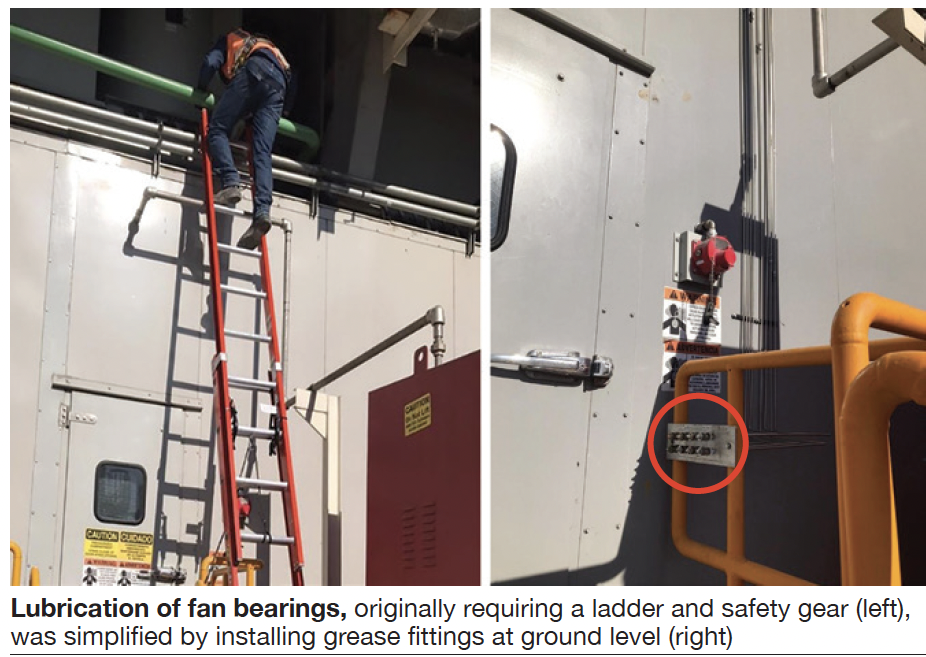
Solution. Goal was to create a way to lubricate the fans that was more accessible to technicians and to reduce the man-hours required for this activity. Staff determined the optimal approach was to place the grease fittings at ground level and guide the grease through tubing to the fan and motor bearings.
To do this it was necessary to design the lubrication system with input from operations personnel to assure installation of the rack of grease fittings (photo, right) was located appropriately. Staff decided to make the connections from the bearings to the rack grease fittings using economical tubing installed by plant personnel, to minimize cost. The project took about two weeks to complete.
Results. This solution eliminates the need for ladder, harness, and lifeline to lubricate fan bearings, thereby eliminating the risks of falls and crushing. In addition, the activity now is performed by only one technician and the lubrication time has been reduced to 1.32 hours per month, down from 16 hours.
Project participants:
Alonso Saldivar, maintenance manager
Andres Hernandez, shift supervisor
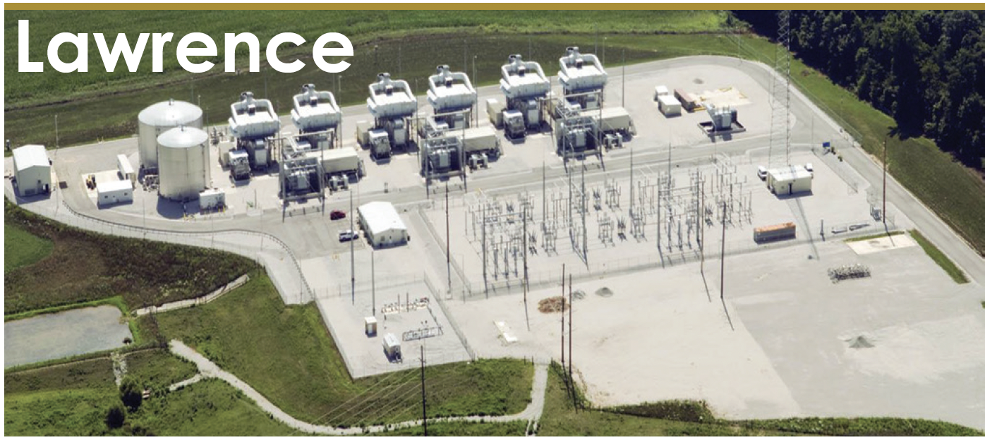
Lawrence Generating Station
Owned by Hoosier Energy (four units) and Wabash Valley Power Assn (two units) Operated by NAES Corp
258 MW, six simple-cycle LM6000 natural-gas-fired peaking units, located in Lawrence County,
Ind, and connected to Hoosier’s 161-kV transmission line
Plant manager: Robert VanDenburgh
Fuel-compartment wind block eliminates unit trips
Challenge. Lawrence County experienced several fuel/water compartment pressure problems during inclement weather, especially during windy conditions. Increased wind velocity entering the fuel compartment inlet duct caused erratic compartment pressures.
During normal operations, the fuel/water compartment pressure is 0.15 – 0.20 in. H2O. However, high winds directly entering the fuel-compartment inlet duct caused a drop in deltaP to as low as 0.05 in. H2O. Such a low signal from the transmitter activates the low-deltaP alarm, which must be cleared within 60 consecutive minutes, to prevent the Woodward control system from activating the LM6000 SML trip. Note that immediate action is required to restore proper fuel- compartment pressure.
Solution. Plant O&M technicians collaborated with local sheet-metal workers to create a stationary wind block, located 6 in. in front of the fuel-compartment inlet duct and securely fixed to the concrete below. It allows more than enough air to enter the inlet duct to maintain proper compartment pressure while preventing wind from directly entering the duct.
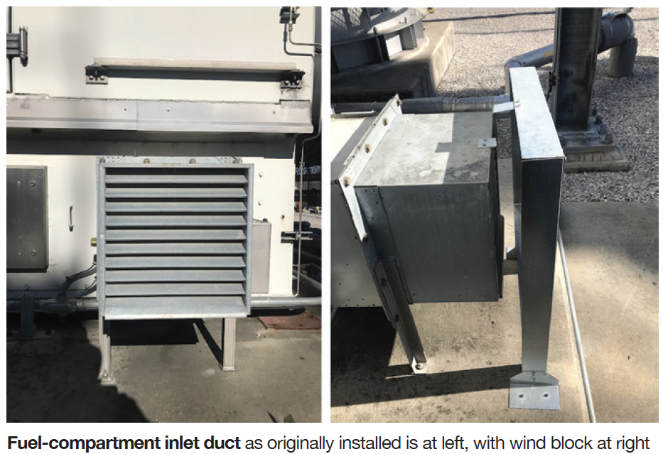
Results. Following installation of the wind blocks on all six units, no impedance to air flow was observed; compartment pressures were normal regardless of weather conditions. SML shutdowns caused by high winds entering the fuel compartment have been eliminated.
Project participants:
Matthew O’Hara, lead OMT
Jared Thomas, O&M/IC&E technician
Kevin Wildner, OMT
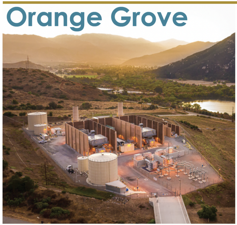
Orange Grove Energy
Owned by J-Power USA
Operated by NAES Corp
96-MW, gas-fired, two-unit, peaking facility located in Pala, Calif
Plant manager: John Hutson
Challenge. Orange Grove Energy faced many obstacles in its first several years of operation. Examples: OGE had four plant managers within two years of commissioning, the entire hourly staff turned over in the first few years, and there were four asset managers during Year Three. Plus, the plant received multiple environmental NOVs (notices of violation) annually, and its safety culture would have been classified as poor.
Solution. By 2014 the site was on the verge of hiring its fifth plant manager, morale was low, and there seemed to be no solution to preventing air-permit NOVs on a semi-annual basis. In late 2014, the site embarked on a positive trajectory that would later pay dividends beyond what would have been imagined earlier.
Staff ratified a set of “Shared Values and Guiding Principles,” agreeing that to become what we wanted to be as a team, we had to be held accountable to those values. Job candidates were introduced to the “Shared Values and Guiding Principles” and had to support and embrace them before an employment offer was made.
In addition to these values, the team agreed that they should be able to enjoy their work. A workplace free of harassment, of course, but the team also encouraged fun and celebration, which became the new expectation at OGE.
“Shared Values and Guiding Principles” gave the team a firm foundation of knowing who we were and what was expected of those who worked at OGE. The site began to consciously embrace employee empowerment. Each team member was given various projects and the freedom and responsibility to own those projects, and expected to lead them to completion.
Ideas were not only desired but expected: People began exchanging solutions and ideas in daily and monthly meetings with the intention of prioritizing issues and finding the best solutions possible to improve the site.
By the end of 2015, the site had transitioned into the NAES O&M company, still owned by J- Power USA, and had made two key personnel changes. Those hired in 2015 were largely evaluated on their ability to fit into the new OGE culture and how they would be able/willing to drive cultural-change improvements at OGE.
NAES brought with it additional operational and safety programs. The key was that the OGE team embraced those corporate policies and worked hard to make them their own. Embracing the structure NAES brought gave the site additional clarity and continuity which helped ensure the employees felt supported from a corporate level.
In 2016, OGE was beginning to improve, as it was the first year since commissioning that the site did not receive an environmental NOV. Additionally, the plant implemented a site cost- saving initiative with a goal of reducing costs by more than $100,000 annually. The team at OGE was happier and becoming more productive.
Late in 2016, OGE conducted a comprehensive anonymous “Cultural Survey and Disc Assessment” with the staff. The Cultural Survey was intended to identify two things: (1) Overall status of the employee’s perception of OGE culture, and (2) Specific areas still requiring focus. The overall measured results were surprisingly higher than expected, but it did reveal areas in need of improvement. There was still plenty of work and opportunity to improve in order to get where we wanted to be as a team.
The Disc Assessment focused on teaching personnel about their own personalities and the personalities of others. The employees would use this information to communicate better with each other. The two surveys were endorsed by ITOCHU, NAES’s parent company. A professional facilitator helped lead the team in maximizing the learning gained from the exercise.
In 2018, OGE convinced the plant owner to reorganize the facility to better meet its current needs. One action was to eliminate the plant administrator position and replace that role with a day-shift lead OMT, who would fill in for vacations, sick call outs, and training coverage. The plant-admin duties would be shared by the team—largely distributed between the plant manager and lead OMT. Staff efficiency increased significantly.
Results. A collective focus on improving site culture has produced operational excellence at OGE. It is a rewarding workplace for all employees. Countless programs and projects have been developed and implemented by the site team, programs and projects they own as leaders. One important result: No safety or environmental violations for four years running.
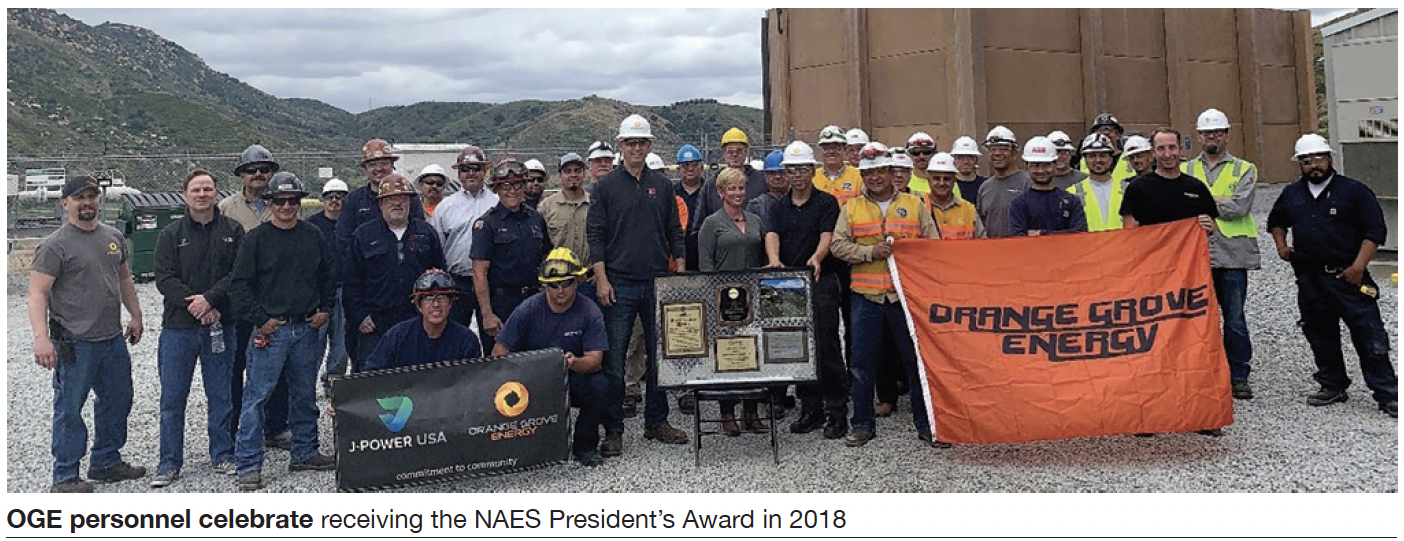
Another: The plant received the 2018 NAES President’s Award, given to only one facility in a fleet of more than 170 plants nationwide. Among other accomplishments:
-
- OGE was certified as a Cal-OSHA VPP Star facility within one year of its initial application. Operationally, OGE recorded its best-ever contractual availability of 7% in 2019.
- It is approaching Year Two without any staff turnover, another site
Aside from OGE’s awards and recognition, there are material financial impacts that have been realized by the culture change that’s taken place at OGE over the past several years. The turnover costs associated with replacing technicians is valued at $35,000 per year. Improved capacity revenues resulting from increased plant availability is valued at $120,000. Initiatives driven by better project leadership and cost sourcing has consistently produced over $110,000 annually in bottom-line cost savings. per year in cost savings from the bottom line.
Best-practice capex efforts and work processes have significantly reduced costs over $100,000 per year. Efficiency gains in work performance and shift coverage driven from reorganization has reduced labor costs by $30,000 annually. Eliminating permit violations has saved another $10,000. In sum, the improvements made at OGE have produced an annual benefit of more than $400,000.
Project participants:
Anthony Moretto, lead OMT
OMTs: Al DeLuna, Erik Cherry, Gregg Stephens, and Paul Braemer
Ramiro Garcia, compliance manager
John Hutson, plant manager
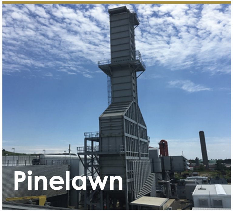
Pinelawn Power LLC
Owned by J-Power USA Operated by NAES Corp
80-MW, dual-fuel, 1 × 1 combined cycle located in West Babylon, NY
Plant manager: Kenneth Ford
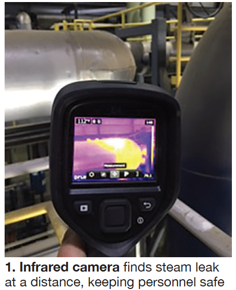 Infrared camera finds steam leak
Challenge was to find the location of a steam leak on insulated and covered high- pressure steam piping. The leak was a minor one and initially identified by condensed moisture dripping from a seam on the insulation covering. The site hoped to locate the leak without jeopardizing the safety of plant personnel and having to remove a large amount of insulation and associated covering.
Solution. The site deployed its infrared camera (initially purchased to aid in identification of electrical hotspots) to pinpoint the leak location. From a safe distance, the infrared camera was used to scan the surface temperature of the insulation (Fig 1) and quickly find the leak. Once the piping was cool, staff removed the insulation in the affected area to reveal the small weld defect responsible.
Results. Use of an infrared camera to locate the leak reduced the hazards to involved personnel and also helped reduce restoration costs by minimizing the amount of insulation requiring removal.
Project participants: Mark Whitney, O&M manager
Utility cart ladder/accessory rack fabrication, installation
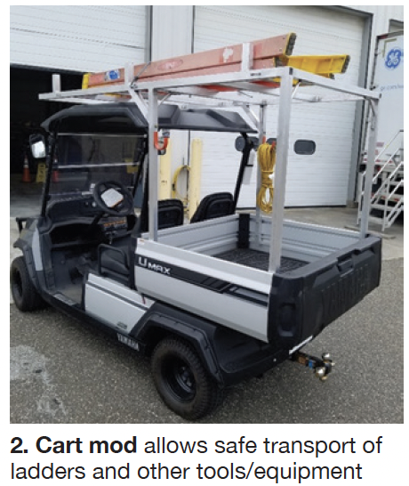 Challenge. The site utility cart manufacturer did not offer an option for a ladder/accessory rack. Staff wanted to increase the utility of the cart by including provision for safe transport of ladders and other tools/equipment. Personnel had to ensure that any addition to the utility cart would not interfere with its tilting-bed feature or exceed the carrying capacity.
Solution. Site OMTs designed, fabricated, and installed a custom ladder rack out of aluminum square tubing. Aluminum was chosen for its superior corrosion resistance, low weight characteristic, and ease of construction.
Results. Addition of the ladder/accessory rack (Fig 2) has significantly improved the usefulness of the cart and simultaneously created a safer work environment for site personnel by decreasing the need for manual carrying of ladders, tools, and other equipment to work locations throughout the plant.
Project participants: Frank Pagano and John Stral, OMTs
Add storage rack to forklift
Challenge. Site personnel identified an unsafe work practice whereby the floor of the site forklift could potentially be used to transport tools, rigging, or other equipment, thereby obstructing free and clear access to forklift foot pedals and impeding operator entry/egress.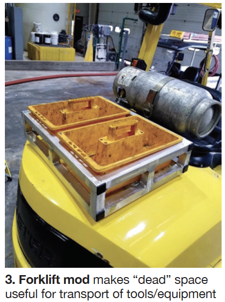
Solution. Plant technicians designed, fabricated, and installed a removable storage rack made of aluminum square tubing. The rack was designed to accommodate two portable tool totes. Aluminum was chosen for its superior corrosion resistance, low weight characteristic, and ease of construction.
Results. Addition of the storage rack to the forklift has improved its usefulness by converting previous “dead” space into new storage space and simultaneously creating a safer work environment for site personnel by decreasing the chances that staff would be tempted to use the floor of the forklift for transport of tools or equipment.
Project participants: Frank Pagano and John Stral, OMTs
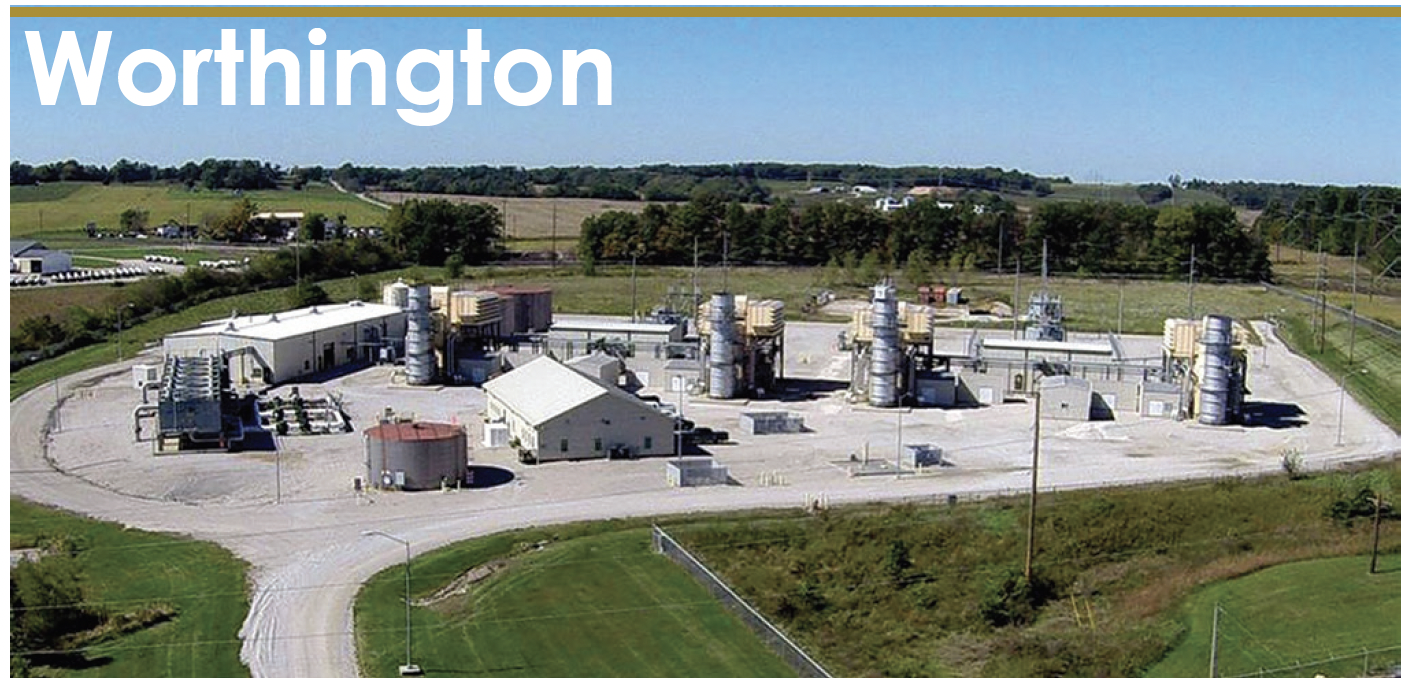
Worthington Generating Station
Owned by Hoosier Energy Rural Electric Co-op Inc Operated by NAES Corp
174 MW, four simple-cycle LM6000 natural-gas-fired peaking units, located in Greene County, Ind, and connected to Hoosier’s 138-kV transmission line
Plant manager: Robert VanDenburgh
Challenge. The S&S packages for Worthington’s gas turbines have two lights that when working properly will illuminate the entire engine space. However, these incandescent lamps constantly fail and are extremely unreliable. Inevitably, technicians have to replace the compartment lights prior to completing their assignments.
This can be dangerous and extremely time-consuming, requiring fall protection given the locations of the bulbs and a LOTO to eliminate the shock hazard. The challenge presented to the safety committee was how to improve the longevity, dependability, and reliability of package lighting. Better lighting would greatly reduce the amount of time technicians spend donning fall protection and working under the lighting LOTO clearance.
Solution. The safety committee discussed several compartment lighting options and made the decision to install industrial LED bulbs. Staff purchased the bulbs and hired an electrician to inspect the wiring and selector switches. Plant technicians removed the old light bulbs from each of the compartment light fixtures and replaced them with the new LED bulbs.
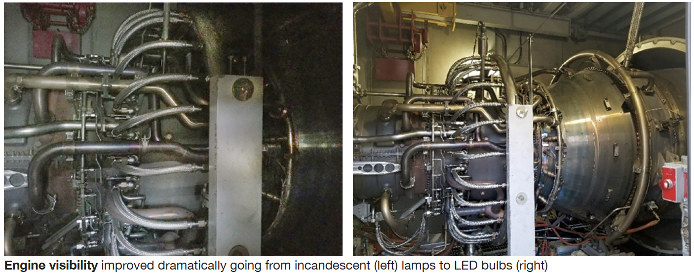
Results. The LED lights are extremely reliable. Turbine compartment visibility has improved dramatically (photos). The selector switch on each side of the package is reliable. LED lamp longevity will both reduce the number of LOTOs needed to replace lamps and time spent in fall protection. Upgrading package lighting significantly decreased the amount of time needed to complete PM work in the package.
Project participants: Matthew O’Hara, OMT
Jason Robertson, O&M/ICE tech William Hooker, OMT
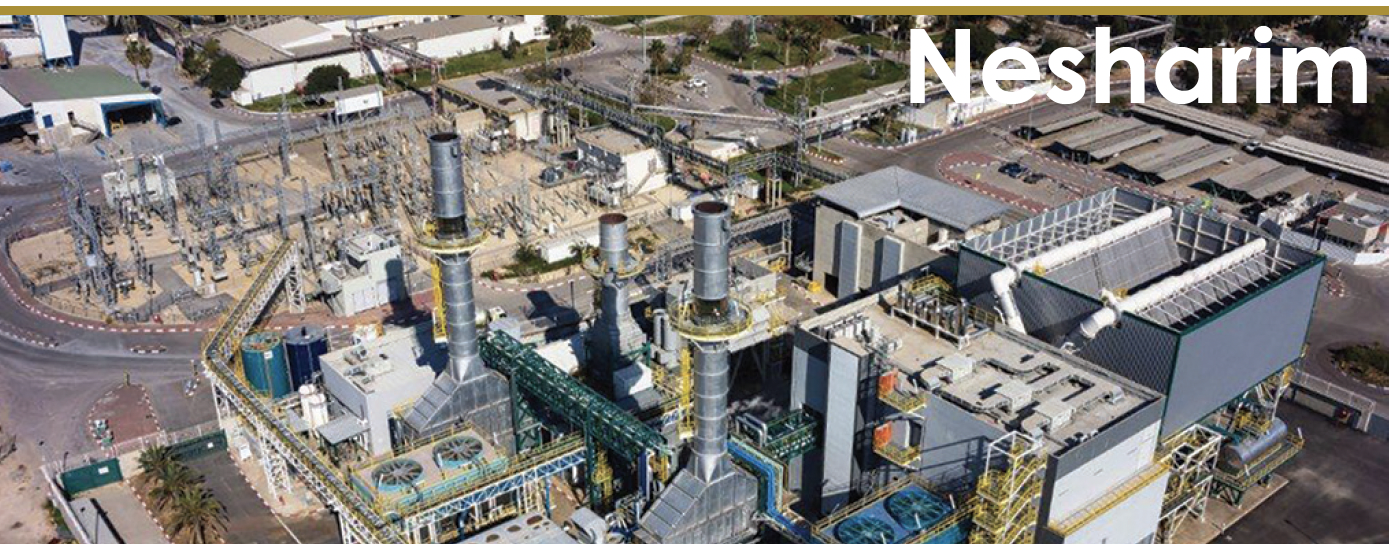
Nesharim Leading Energy
Owned by Clal Industries
Operated by Mashav Initiating and Development
120-MW, gas-fired, 2 × 1 combined cycle located in Ramla, Israel
Plant manager: Kobi Ivenshitz
Insulating filter house roof conserves energy
Challenge. Nesharim’s filter house is installed over its gas turbines and doubles as a roof for the units. The upper portion of the sheet-metal structure is exposed to the sun’s radiation. An electric chiller is used to cool turbine inlet air to 46F the entire year. In summer, solar radiation heats up the filter house to more than 130F, resulting in a loss of cooling energy and a loss of power produced by the turbines.
Solution. A nano-ceramic insulation—in effect, a 0.2-in.-thick coating of “paint”— was applied as a fine layer on top of the cooling area, on the entire upper surface and side walls. By insulating surfaces exposed to the sun’s radiation, less energy is required for cooling inlet air, and air that has been cooled is not reheated by the sun. This fix has increased power generation and reduced parasitic power consumption. Thus turbine efficiency has increased.
Results:
-
- When comparing the chillers under identical ambient temperature/humidity conditions before and after the insulation was applied, there is a saving of about 60 kW per hour in chiller energy consumption, and a decrease in the inlet air temperature at the turbine entrance of about 3.6 deg
- The chiller’s ability to reduce air inlet temperature is improved and its response time to changes in ambient humidity and temperature is
- The insulation provides an additional layer of protection from corrosion and water penetration into the filter
Project participant: Kobi Ivenshitz, plant manager
Reducing offline water-wash time for gas turbines
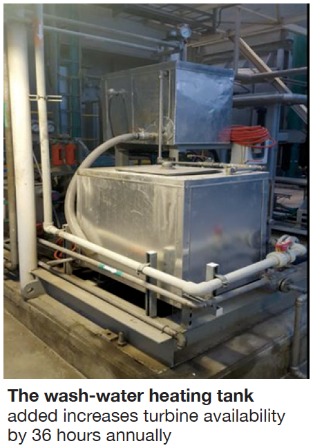 Challenge. Compressors are water-washed monthly as part of the plant’s gas-turbine maintenance program and to maintain maximum output. During the offline wash there is a loss in production time of about eight hours, reducing turbine availability by about 1%. The water-wash process involves eight washes of water together with detergent. During the first two wash cycles, the fluid is heated to about 165F. The plant was commissioned with only one wash-water tank, so it took time to warm the water for the second hot wash.
Solution. Plant duplicated the original wash-water tank and added the second tank in series with the first (photo). With this improvement, heating is carried out in the two tanks simultaneously, thereby saving a few hours. In addition, the OEM’s software was modified to shorten ineffective processes, which saved more time.
Results. This improvement has reduced the offline water-wash time by about half, allowing a faster return to production. The second tank heats the water for the second cycle before and during the first cycle, enabling the second rinse cycle to begin just a few minutes after the first rinse ends. Previously there was a waiting period of two and a half hours. The benefits:
-
- Rinse time reduced from eight hours to four (breaker to breaker).
- Turbine availability increased by 36 hours
Project participant: Kobi Ivenshitz, plant manager
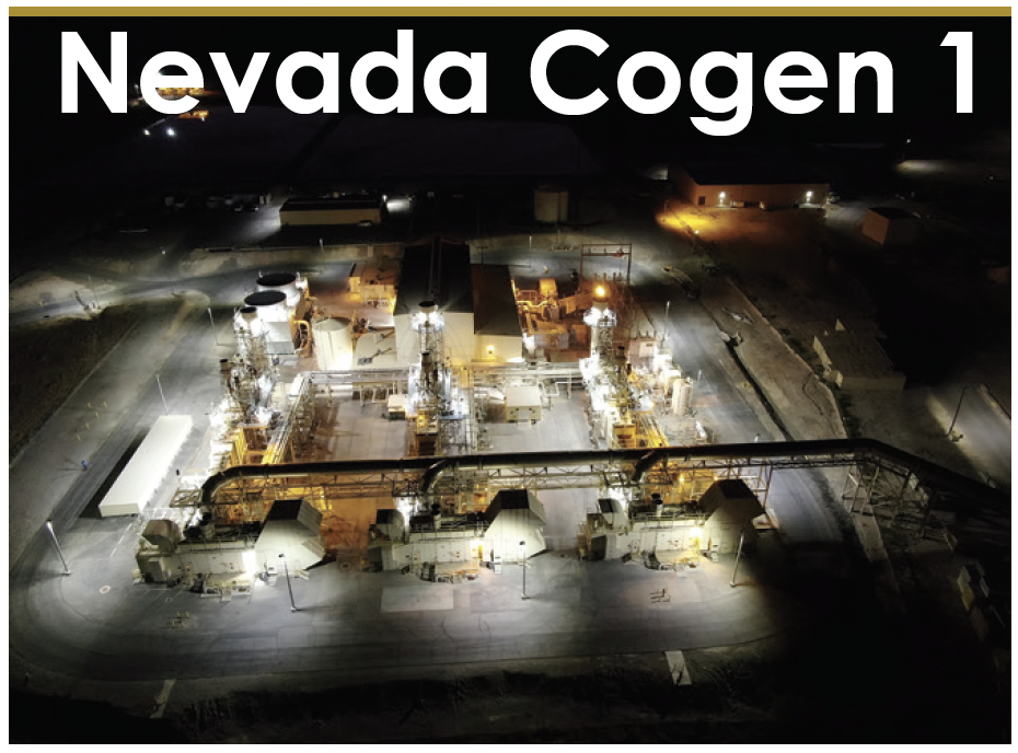
Nevada Cogeneration Associates No. 1
Owned by Northern Star Generation Services Operated by CAMS
90-MW, gas-fired, 3 × 1 LM2500-powered combined-cycle cogeneration facility located in Las Vegas, NV
Plant manager: Howard Forepaugh
Challenge. Nevada Cogen’s gas-turbine packages use an evaporative system to cool engine inlet air. There are two levels of inlet air flow. The original configuration used 1-in. manual gate valves and a roto flowmeter, one for the lower level and one for the upper level of each turbine.
When the inlet temperature required adjustment, the control room operator would direct his outside operator to do that. If that person was tied up with a delivery or another task, then the adjustment would wait until the operator was finished. Thus, the turbines could not run at maximum efficiency all the time.
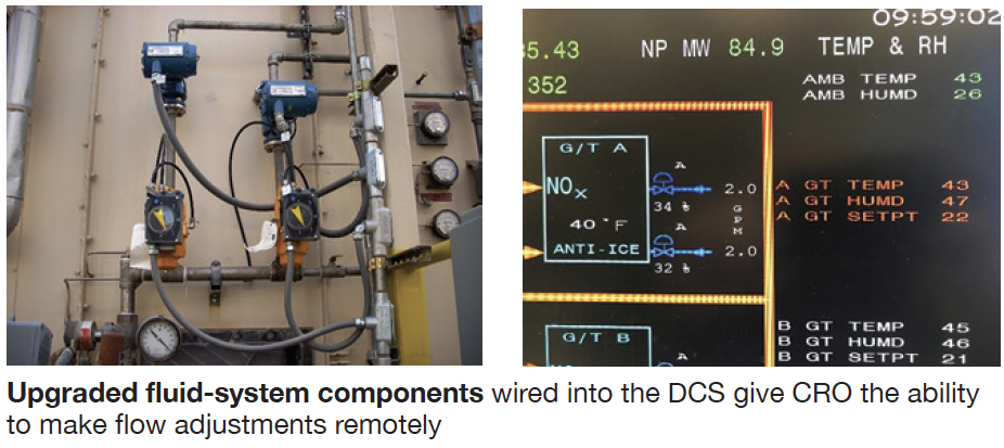
Solution. Install Mag flowmeters and characterized ball valves (photo, left) with electropneumatic positioners. Wire the flowmeters and valve controls into the DCS, giving the CRO the ability to monitor flow (photo, right) and make adjustments remotely.
Results. The new system has worked extremely well, and the outside operator is free to concentrate on other responsibilities.
Project participants:
Shawn Malcolm, O&M manager
Justin Robbins, I&E technician
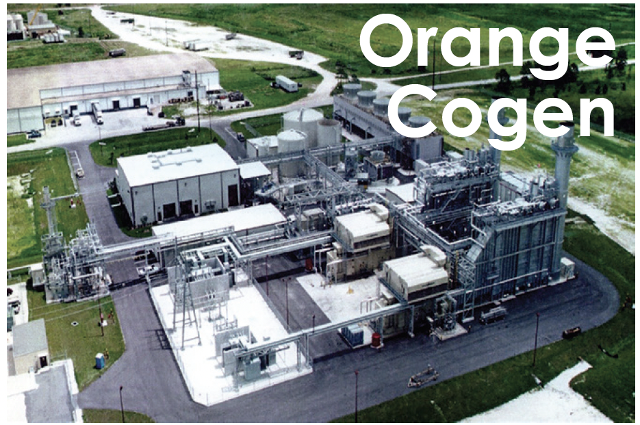
Orange Cogeneration
Owned by Northern Star Generation
Operated by Consolidated Asset Management Services LLC
104 MW, gas-fired 2 × 1 combined-cycle cogeneration plant powered by DLN-equipped LM6000 engines, located in Bartow, Fla. Condensing, extraction steam turbine is rated 25 MW.
Steam is sold to producers of orange juice and ethanol
Plant manager: Allen Czerkiewicz
Challenge.. Florida receives approximately 1.2 million lightning strikes annually and leads the nation in lightning-related deaths. Outside work can be extremely hazardous, and potentially deadly, during a thunderstorm. For this reason, no outside work is permitted at Orange Cogen when lightning is detected within 10 miles of the facility.
The existing lightning detection system at the plant feeds a display in the control room that flashes red and notifies the operator when lightning is detected within 10 miles of the facility. System includes a 30-min countdown timer that resets each time more lightning is detected. When lightning is detected, the control room operator announces same to all plant personnel via the intercom and plant PA system. The operator informs personnel of the danger and reminds personnel to seek shelter and stop outside work until the all-clear is given.
Personnel (contractors, vendors, delivery personnel) who entered the facility after the warning announcements were made had no way of knowing that the plant was under a lightning warning and would expose themselves to great risk.
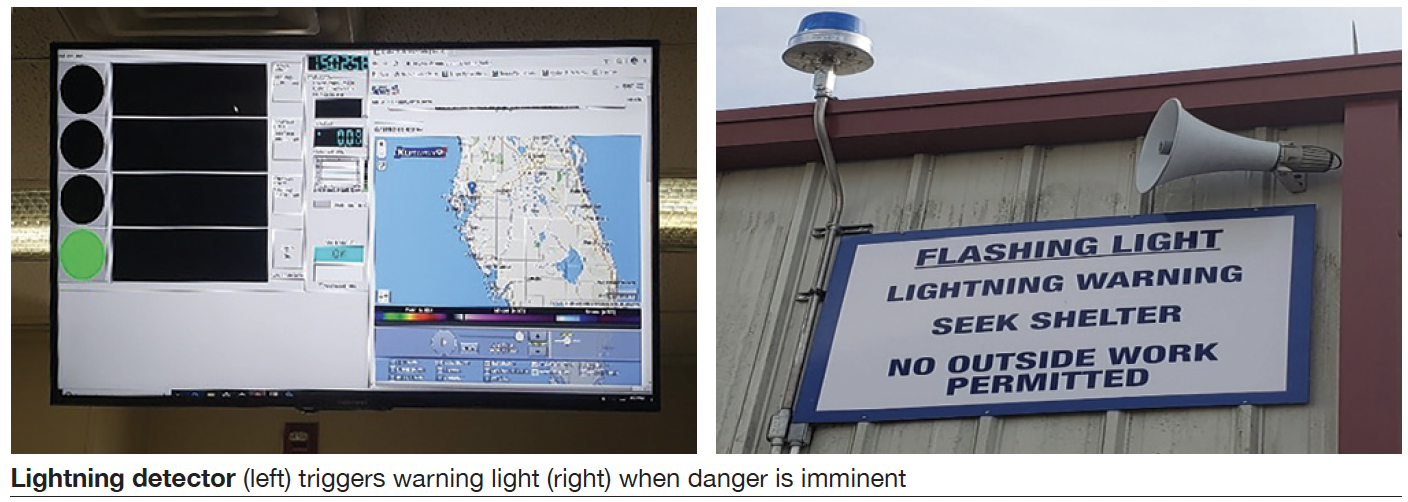
Solution. A large flashing blue strobe light was purchased and installed at a very conspicuous location that anyone entering the facility would not be able to miss. A connection on the lightning detector module (photo, left) is used to transmit a signal to the blue light, causing it to activate (photo, right).
Results. Since installation in September 2019, the system has performed flawlessly. Any individual entering the facility now has an obvious warning to alert them of any potential lightning dangers, making the plant safer for everyone onsite.
Project participants:
Ken Judd, materials coordinator
Charles Chancey, I&E technician
Kristen Albritton, EHS manager
The 501F Users group is well known for its collaborative brand of user roundtable discussions and robust forum. What follows are recaps of user presentations from their 2020 meeting. More details on these and access to both the 2020 and 2021 conference presentations and resources are available at the 501F Users Group website and forum.
Analysis of K-N steam-turbine vibrations, corrective actions, results
This presentation is recommended reading by all dealing with vibration issues on the No. 1 bearing for a Siemens KN steam turbine—a combination thrust/radial bearing at the front of the HP/IP section. It is based on a thorough analysis by one of the industry’s most experienced utility staff engineers and co-authored by the plant manager.
Some background notes: The steamer is an integral part of a 2 × 1 501FD-powered combined cycle, COD 2004, with a history of more than 2000 starts—up to 450 starts some years. Plant was sold by the IPP developer to the current utility owner in 2017. During the major inspection that year, work included the following: an OEM mod—hard-facing of bearing keys to address a fretting issue; high-speed shop balance; and KN coupling alignment. Post outage, the problematic bearing was reworked by the OEM three times in less than three years with changes made to bearing preload, clearances, etc, without resolving the vibration issue to the owner’s satisfaction.
Observations related to the vibration problem that helped to guide the ensuing analytical effort and corrective action included these:
-
- Bearing vibration above 9 mils peak-to-peak at high loads with duct firing and power augmentation (PAG).
- Small thrust movement (1 to 2 mils) might change vibration. Curtailment of PAG reduced vibration.
- Bearing seemed to like the thrust load in a specific direction.
- Unit may run fine in a 1 × 1 configuration (2 to 4 mils), then jump to 4 to 9 mils in 2 × 1.
- Problem seemed isolated to the No. 1 bearing.
More than half the presentation’s slides focused on the in-depth vibration analysis, with detailed drawings and charts of value to anyone similarly challenged. Among the findings of the outage taken in 2019 were the following:
-
- Keys were loose and seat worn, as the analytical work predicted.
- Bearing was aligned to the pedestal not to the journal. Elimination of the tapered gap allowed keys to fit as intended.
Results of the corrective actions taken included these:
-
- Vibration, which had been 4 to 9 mils at the No. 1 bearing, was reduced to 1.4 to 1.7 mils.
- Now there was nearly no vibration change with load change.
- Axial float near the assembled clearance was less than 12 mils, down from more than 20 mils.
The bottom line: The project was considered a success with the likely outcome that fretting may not increase clearances over time.
Lessons learned were several, with most applicable to many other plant challenges:
-
- Participate in users groups to gain the experience you might not have. Keep in mind, too, that you only get out what you put into any project. And, if you don’t share, don’t expect someone else to help you.
- Better to spend time analyzing data, and on understanding what to expect, than to go on a “witch-hunt” disassembly outage.
- Trust, but verify what’s being done, even it’s the experienced OEM doing the work.
- Never let a “good opinion” stand in the way of data, facts, figures, physics, etc.
- Check things out, document, take photos, understand what’s being done while the unit is apart—not after it doesn’t run well.
- An OEM data sheet may be signed off and a unit closed up, but if you don’t know how and where those data were sourced from, the data sheet is just a piece of paper.
- When your issues have been addressed unsuccessfully more than once, and there are reams of data not understood, don’t look for a “knight in white armor” to solve your problems. Own them!
GVPI stator-bar failures, lessons learned
This is a well-illustrated presentation many O&M technicians can learn from. It addresses the failures of two different SGEN6-1000A generators serving gas turbines in a 4 × 1 combined cycle. The four units are characterized by globally vacuum pressure impregnated (GVPI) stator windings.
The first failure was on a 245-MVA, 15-kV machine after nine years of operation. An incorrect cable termination was used during plant construction. The spec called for unshielded cable, but 2/0 shielded cable was used and the shielding was not removed for the approximately 8 in. needed at termination. Because the shielding was not stripped back, it was within strike distance when the fault occurred. The current jumped into the shield rather than travel in the cable conductor, thereby overheating and failing the cable.
The second unit failed a stator-winding hi-pot after 10 years of operation. The test target was 33 kV, 2.2 times rated voltage. In one phase a bar failed at 30 kV and in another phase a bar failed at 16 kV. Visual inspection showed an “insulation anomaly” on the top surface at core exit on both failed bars. Two other bars that had not failed also displayed the same insulation anomaly.
All four stator bars, plus one non-failed bar without ridge as baseline sample, were extracted for root-cause analysis. A full rewind was performed on this stator. The slides did not comment on the difficulties of removing bars from a GVPI winding.
A CT scan on two failed bars showed signs of what appeared to be insulation cracking internal to the bar at the location of the ridges on both bars that failed the hi-pot, as well as the other two bars with ridges in the insulation. These flaws would be a very serious concern to the fleet of similar units, but the slides did not comment on this issue.
Generator inspection findings
The inspection findings on a generator serving one of three gas turbines at this 501FD2-powered, 830-MW combined cycle, COD 2005, are well-illustrated in the presentation and would have value as a training tool.
Minor cracks and greasing are in evidence at non-critical locations in the connection rings, stator endwindings, and leads to high-voltage bushings. Plus, some greasing was found on back-of-core ventilation seals. Note that generator design relied heavily on bonding with epoxy between ties, blocking, and leads.
While the slides do not mention corrective actions taken, if any, they likely would have been minor given the satisfactory condition of the machine, as portrayed in the photos. Replacement of main flex leads during the outage was mentioned; however, this was done based on the OEM’s calendar-based recommendation, not because of damage or defect.
Integrating the direct-air-injection system into BOP operations
Uneven cooling of Siemens F-class gas turbines after shutdown sometimes leads to rubbing of turbine and/or compressor blades against the case. The OEM determined that by injecting cool air into the machine during shutdown, a homogeneous mixture of air can keep the top and bottom of the unit at roughly the same temperature and eliminate case bowing.
The standard OEM-supplied direct-air injection system (DAIS) would have used a stand-alone air compressor and injection hardware for each 501FD3 (with partial FD6 upgrade) at this 535-MW 2 × 1 combined cycle. However, plant engineers saw an opportunity to do more with the DAIS compressors.
It installed variable-speed compressors instead of the OEM-supplied conventional air packages and incorporated them into the plant’s original air system, plus the piping system that extracts air from the cold-air side of the rotor air coolers (RAC, a/k/a kettle boilers). A slide in the presentation provides a system diagram.
Given the RAC cold-air side temperature is 390F or above, an additional air-to-air exchanger with a variable-speed fan was installed to reduce that temperature to less than 100F. Extraction air, from either the Unit 1 or Unit 2 compressor, is supplied to a common header that can satisfy BOP air requirements as well as the DAIS needs for an offline turbine.
Benefits of this lineup include the following:
-
- The original BOP service compressors rarely operate.
- GT extraction air typically supplies all of the plant’s needs.
- If no gas-turbine compressor air is available, the DAIS units supply plant air.
- Energy is saved—about 680 MWh annually.
Combined-cycle upgrade to T3000 V8.2
Owner/operators planning a control-system upgrade from T3000 to T3000 Version 8.2 would benefit from reviewing the project overview and management and execution slides provided by staff at a plant that recently converted two 2 × 1 power blocks to V8.2. The gas turbines at this facility are 501FD2s, the steam turbines are KNs.
A few of the lessons learned shared at the meeting are these:
-
- During the initial meeting with the OEM, ask for a full explanation of the major differences between your system and the upgrade—such as PI interface platform, hardware, etc.
- Get your company’s PI administrator involved at the beginning of the project.
- Obtain the Modbus list for all third-party interfaces.
- Keep the existing T3000 application server powered up and use it as a reference.
- The more control-room operator eyes the better.
Penflex pipe failure experience
Plant experienced a step change of 4 deg F in the flashback temperature expected on one combustor. Two days later there was an additional step change of 8 deg F. These step changes corresponded to a blade-path temperature shift of about 15 deg F from the expected value.
The combustor section was inspected and a Row 1 vane was found with a heavy breach and an adjacent vane with moderate erosion/possible breach. Siemens opened the unit finding several parts burned up; plus, the Penflex pipe on the right-side top had failed. A full combustion inspection was conducted.
Investigators did not attribute the R1 problem to the Penflex pipe failure. The damaged pipe was replaced. None of the Penflex pipes on the unit showed any damage.


