![]() Don Punwani, executive director of the Turbine Inlet Cooling Association, called the CCJ editors to say the organization had elected officers and directors for 2021-2022. Recall that TIC is a resilient, sustainable, fast-response, and carbon-reduction option for gas-turbine owner/operators.
Don Punwani, executive director of the Turbine Inlet Cooling Association, called the CCJ editors to say the organization had elected officers and directors for 2021-2022. Recall that TIC is a resilient, sustainable, fast-response, and carbon-reduction option for gas-turbine owner/operators.
Learn what inlet cooling can do for your plant/company by visiting the resource-rich TICA website when time allows. It offers a TIC performance calculator, experience database of over 400 installations, webinars, technical papers, etc.
The non-profit trade association, established 20 years ago, develops and disseminates worldwide information on all TIC technology options—wetted media, fogging, wet compression, mechanical chiller system, absorption cooling systems, and LNG vaporization systems, and various combinations of these alternatives.
Don Shepherd of Caldwell Energy was elected chairman for the new term; he had been vice chair. Andrew Sickler of Baltimore Aircoil moved up to vice chair following a term as president. The new president is Rob Pugh of Danfoss, VP previously. Justin Rose of Munters was elected VP and Keith Flitner of Victory Turbine Secretary. Consultant Patricia Graef continues as treasurer. Richard Buckley of Johnson Controls (Asia) is the new director.
European Technology Development Ltd’s (ETD Consulting), International Conference on Power Plant Operation and Flexibility, held in London in July 2018, covered recent developments in plant materials, operation, inspection, maintenance, and costs related to both baseload and cycling operation for different types of plants—including combined cycles. Participants included plant owners/operators, consultants, researchers, manufacturers, and inspection-agency professionals.
Conference organizer Dr Ahmed Shibli, managing director of ETD Consulting, pointed to the following global trends:
-
- Europe is going through the same market changes as North America. Cycling is global.
- Some countries have more cycling and low-load experience than North America—such as those with geothermal and hydroelectric plants that cause varied operation of fuel-fired assets. This experience base has wide-ranging value.
- Europe and Japan are taking active roles in high-temperature materials development and testing.
Shibli’s primary purpose in arranging the meeting was to help identify the basic causes of equipment problems in both baseload and cycling units, and to clarify modifications, inspections, and procedures that will minimize costs.
Who wins when plant components fail? A question asked by one of the first speakers, David Allen of Impact PowerTech Ltd (UK), “Who wins when plant components fail?” set the tone for the conference and was the perfect segue for his presentation on the upgrading of materials and welds. Allen’s next question was equally pointed: “Why do we so often stick with last-century technology?”
The speaker began with a philosophical look at planned obsolescence. He cited interesting examples from the automobile, white goods, and communications industries. Participants were captivated, and on alert for more.
Allen did not claim current evidence of planned obsolescence within the power industry, and in fact stated that a manufacturer with a unique design is careful to maintain its good reputation.
But he did note some dangers similar to those expressed by Eskom (South Africa) at last year’s Air-Cooled Condenser Users Group meeting in Las Vegas. To wit, we all experience the ongoing pressures for low bids, rapid investment payback, and increasingly stringent trading conditions.
The potential menace is commonly applied standards that fail to ensure the most reliable long-term component operation. In other words, once a supplier meets the standards or codes in the specification, further refinements or improvements can become less important (and more expensive) to the supplier. The same is true on qualifying bids for component supply. Providers’ reputations are at less risk as long as they meet the qualifications.
Perhaps because “innovation brings risk,” or because “regular repair and maintenance activities provide jobs,” we could be letting ourselves down, suggested Allen. And in his words, “We are still building new plants with 40-year-old materials (P91, Alloy 617) and ignoring the newer, potentially better alternatives.”
And how has market-driven flexible operation changed things? “Cycling makes it worse!”
Details have become clear, stressed Allen:
-
- Flexible operation only makes service exposure more onerous.
- Thermomechanical transients cause additional cyclic loading, which is conducive to the following: 1. Mechanical and thermal fatigue cracking, 2. Creep-fatigue cracking (with creep ductility exhaustion attributed to repeated transient creep strain), and 3. Creep cracking (with creep life reduction caused by increased loading).
- Poor temperature control can severely shorten creep life.
- Creep issues do not go away; they get much worse.
- Fatigue brings additional challenges.
- Sticking with last-century technology increases risk!
So how do owners/operators minimize the potential costs? Allen outlined some thoughts:
- 1. Design out “at-risk features” (thickness and materials mismatches, closely spaced header stubs, dissimilar-metal welds, etc).
- 2. Improve temperature control during startups and transients.
- 3. Make components thinner—perhaps.
-
- Thinner components minimize thermal/mechanical mismatch loading and may therefore perform better when fatigue is a problem.
- But thinner components will experience higher pressure stresses and may therefore perform worse when creep is a problem.
Allen reviewed typical owner/operator options. Some choose to continue operation until plant end-of-life, mindful primarily of safety. Many take the financial hit and accept high inspection, repair, and replacement costs. The better strategy is to install upgraded retrofit components with stronger materials and welds at the same thickness (better for creep) or thinner (better for fatigue).
He then presented details and examples of current P92 materials with good-quality heat treatment, labeling this “a materials upgrade solution that is ready now.” Following in-depth discussions of various manufacturing methods, heats, ductility, and tensile strength, he asked participants to “Stop fearing P92!”
And he gave specifics from a recent review, showing a “strong correlation between heat treatment and ductility.” He concluded that “normalizing is about twice as important as tempering. Under-normalizing is the main problem. Under-tempering makes the problem worse.” And “notably, normalizing time is more important than temperature.”
-
- The four most creep-brittle casts, with long-term average area reduction (Ra) in creep test values in the range of 3% to 12%, all had normalizing times in the range of 0.2 to 0.6 hours.
- The seven next most creep-brittle casts, all with Ra values in the range of 18% to 24%, had normalizing times of 0.2 to 1.0 hours.
- No cast with a normalizing equivalent to 2 hours at 1050C or 1 hour at 1070C had a long-term Ra value lower than 28%.
Summary: This indicates that simple controls on allowable heat treatment can resolve the Grade 92 creep brittleness concern. Further work is ongoing to assess very long-term ductility out to 100,000 hours, and beyond.
Allen next looked at “near-future MarBN, a novel high-alloy steel for powerplants.” This material, being studied primarily in Japan and the UK, is martensite plus boron and nitrogen. The process involves “careful microalloying with boron and limited nitrogen for high creep strength.” Allen listed temperature capability of P92 as about 20 deg C better than P91 and “expects temperature capability of MarBN to be at least 25 deg C better than P92.”
But the microalloying process is extremely sensitive.
Following discussions on welding processes, he offered the following conclusions:
- 1. “Today we can replace P91 with P92.
- 2. Tomorrow we could use MarBN for even greater security.”
 In what was a truly international gathering of scientists and power-industry engineers, European Technology Development Limited (ETD) orchestrated and conducted a virtual conference on high-temperature plant materials, inspection, monitoring, and assessment (MIMA), Oct 27-28, 2020, drawing attendees from 22 countries.
Dr Ahmed Shibli, managing director of ETD Consulting, Leatherhead, England, said that “Although in the past ETD has organized many conferences and training courses throughout the world, this is a unique experience for us.
“Due to Covid-19, such exchange has become prohibitive during 2020 resulting in cancellations of many international conferences, thus limiting access to and exchange of knowledge, data, and discussions on many new and exciting developments.
“This conference is meant for materials and systems developers, plant designers, fabricators, owner/operators, and service providers, as well as researchers and inspection companies,” he continued.
MIMA 2020 was arranged in these six sessions:
1. Materials, including MarBN steels for high-temperature applications.
2. Inspection.
3. Cracking/failures of plant materials, plus operating flexibility and efficiency.
4. Weldments and monitoring.
5. Materials degradation, damage, and life assessment.
6. Risk-based inspection (RBI), reliability-centered maintenance (RCM), and stress analysis.
7. Prerecorded presentations (not discussed live) on risk-based monitoring (RBM), cracking, and modeling.
As you read through the conference highlights below, and have questions, or want to dig deeper into the details, contact Shibli and his team of experts directly @ enquiries@etd-consulting.com. The presentation summaries were compiled by Consulting Editor Steve Stultz, who participated in the meeting, and made his selections based on their applicability to combined-cycle plants.
MarBN in the UK, Japan, Germany, Austria. Shibli opened the meeting thusly: “I would like to especially thank my Japanese colleagues who persuaded ETD to organize this conference. They said no high-temperature plant or materials event has taken place this year in Japan and perhaps ETD could bring together an international community working in this area.”
Session 1 was, therefore, dedicated to ongoing development work with MarBN steels, which are gaining traction in Japan and Europe. At the beginning of 2020, the UK government and industry began a three-year study of these materials, in a project named “Implant,” with coordination by ETD. The general goal is to develop higher-efficiency, less polluting powerplants for the future.
MarBN, a 9Cr martensitic steel with the addition of boron and nitrogen, depends on an extremely sensitive heat-treatment process.
The following six presentations focused on MarBN-related material:
-
- Alloy design of MarBN for boiler and turbine applications at 650C/1200F (National Institute of Materials Science, Japan).
- Development of UK MarBN steel IBN1 for advanced powerplant applications (ETD, UK).
- Casting, welding, and forging of MarBN components (Voestalpine Bohler Welding, et al, Austria and Germany).
- Manufacture of large MarBN steel castings (Goodwin Group, UK).
- Development of the matching filler metal for creep-resistant MarBN (Lincoln Electric Europe).
- Intergranular rupture of the heat-affected zone (HAZ) of welds after short-term creep rupture (Loughborough University, UK).
Materials and inspection. Session 2 compiled recent information on material inspection methods, focusing on innovative techniques. Ignacio Marcelles, Tecnatom SA, Spain, presented an overview of inspection engineering and life assessment with both web-direct and offline access, combined with business-intelligence tools. His premise: both speed and capability of computers will increase progressively, and prices will continue to fall (Moore’s Law).
 Marcelles covered inspection and analysis tools including drones, and remote-operation vehicles and crawlers for buried pipelines and small pipes, as well as tank floors, walls, and ceilings. These included devices for both manual and automated data capture. New software for integrated and 3-D results focused on structural members, valves, and transformers.
Long-term inspection solutions such as these will become more widespread both during and after the pandemic as only the system operators need to be on location. Monitoring and analysis are currently remote and could remain so.
Although security concerns remain with data transmitted away from the plant, benefits are reduced cost, quality of data and analysis, and centralized plant comparison capabilities.
Phased array. John Trelawny, team leader at Uniper Technologies (formerly E.ON) in the UK, discussed an ultrasonic phased-array total focusing method (TFM) for inspection, suggesting that this could perhaps be a solution for the future. “Accuracy of flaw sizing is paramount,” he stressed.
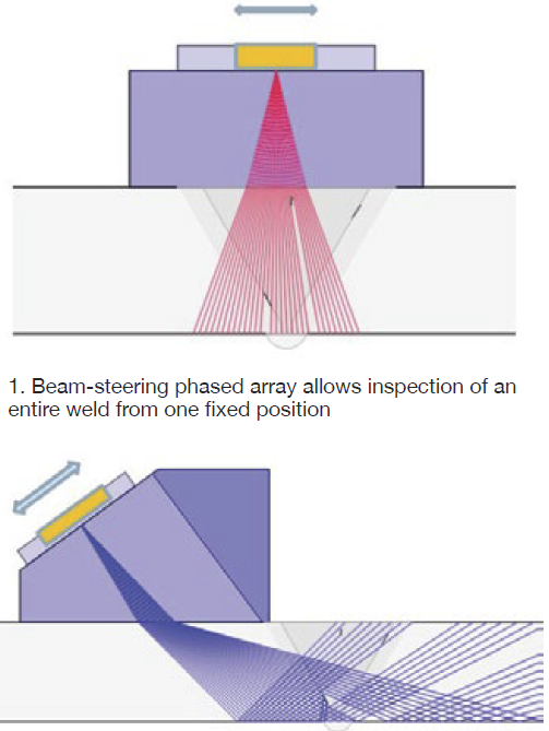
Trelawny offered an example of beam-steering phased array, which uses a probe with multiple elements, each receiving all signals. This technology, tested in both mockup and real-time onsite, allows for angular inspection. The entire weld can be inspected from one fixed position (Fig 1).
He explained TFM in three modes (2T, 3T, and 4T). TFM clarity exceeded that of standard beam steering. Lack of such clarity can cause confusion, he explained.
The presentation showed detailed comparisons of angled phased array versus offset total focusing, among others. Visuals included mockups with testing methods and options, followed by site testing experience and validation.
Some conclusions:
1. TFM is an advancement in ultrasonic technology.
2. For simple butt welds, TFM is superior to current techniques.
3. For complex geometries, TFM can be an advantage, but not in every situation.
Trelawny estimates that phased array is currently used in about 20% of applicable investigations; the remainder, conventional UT. Phased array/TFM is also a very repeatable technique.
Electromagnetic (EM) sensor techniques for creep cavity damage detection and assessment were offered by the Univ of Manchester, ETD, and Nippon Steel Technology Corp, Japan.
Ferromagnetic materials are comprised of polarized magnetic domains which grow and shrink with the application of an external magnetic field. Microstructural changes are based on so-called pinning of these walls by features such as cavities, inclusions, and dislocations. Magnetic properties reveal the microstructural properties.
Univ of Manchester’s John Wilson explained the use of EM on aberrant, mis-heat-treated materials for testing—specifically Grade 91 components. The work was initially developed through the testing of cylindrical samples machined from P91 pipes. He presented the results of BH loops and Magnetic Barkhausen Noise (MBN) on some of the laboratory samples and the tests on in-service pipes, as well as the test-equipment configurations.
Background: A BH loop measures the hysteresis loop flux density (B) versus field intensity (H) of a thin magnetic film sample by applying a field to the sample and measuring the magnetic field produced by the sample’s magnetization. The Barkhausen effect is a name given to the noise in the magnetic output of a ferromagnet when the magnetizing forced applied to it is changed.
A planned follow-up of this work will be an ETD Group Sponsored Project, “Early-Stage Damage Inspection, Repair, and Life Extension of Aberrant P91 Components.” The goal is improved microstructural investigation.
Challenges to industrial deployment, Wilson explained, include:
-
- Irregular surface geometry (tee pieces, etc) in onsite components (problematic for contact techniques).
- Some difficulty in sourcing post-service samples with varying levels of creep.
- Identifying further the effects of surface conditioning (grinding, decarb layer).
Correlations have been established between material (creep, aberrance) and magnetic properties for Grade 91 steel using laboratory measurement systems, but further work is needed on field-deployable devices. Ultimately, this application should support, and later replace, the traditional replication and reduce both testing costs and schedule impact because, unlike replication, it does not require surface preparation. Furthermore, EM can detect damage a few millimeters below the surface which is a distinct advantage over replication.
TesTex. Frank Neil of TesTex, Pittsburgh, Pa, presented three novel techniques: low-frequency electromagnetic to inspect HRSG finned tubes from the outside, the innovative Claw to inspect tube-to-header welds with a balanced-field electromagnetic technique, and a remote-field electromagnetic to inspect HRSG tubes from the inside. All search for corrosion cells and cracks in materials.
In cooperation with EPRI, various new methods are being applied in challenging areas of the combined-cycle powerplant. TesTex methods are used for condenser-tube and auxiliary-boiler inspections, thickness testing on tubing and piping, deaerator heater and storage tank examinations, assessing corrosion under insulation, and a growing number of inspections for balance-of-plant heat exchangers.
Results of specific dry inspection methods, he stated, are competitive with radiography, at reduced cost, improved personnel safety, and less schedule impact.
Life assessment. Dr David Robertson, lead metallurgist at ETD, addressed life-assessment tools and root-cause failure analysis for boiler/HRSG components, highlighting recent experience at various world locations.
For remaining-life assessments, ETD uses an organized, staged approach. Initial inspection-based assessments combine many techniques, often teamed with international NDE partners.
Robertson explained some of the newer techniques, including low-frequency electromagnetic methods for waterwall tubes (see TesTex above) and pulsed eddy current for feedwater piping.
 His specific examples included pulsed eddy current as a screening tool to identify corrosion under insulation (CUI) and flow-accelerated corrosion (FAC) without removing insulation; borescopes for tubes and bends that are difficult to inspect from the outside; and metallurgical assessment of P91 branch connections (reheater outlet headers, for example).
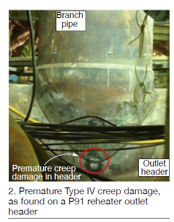
In one example, premature Type IV creep damage was found on a P91 reheater outlet header. At this position, orientation of the HAZ at the flank position of the branch weld is perpendicular to the hoop stress on the header side of the joint. This led to higher risk of Type IV creep damage (Fig 2), similar to that found on longitudinal seam-welded pipe. This was fully analyzed and the client advised to grind out the cavitated area after which the component would be fit for service for another few years.
During the RCA, Robertson reviewed typical scope of work, highlighting a vertical-path HRSG and specifically thermal-mechanical fatigue cracking at tube-to-header welds.
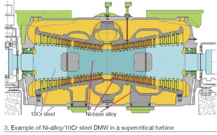
DMWs. Stuart Holdsworth, Swiss Federal Laboratories for Materials Science and Technology (EMPA), reviewed microstructural damage development adjacent to fusion lines of dissimilar metal welds (DMWs). He began with high-temperature damage of a Ni-alloy/10Cr steel DMW in an advanced ultra-supercritical (A-USC) steam turbine application (Fig 3).
He followed with DMW creep-rupture strength reduction and cycle/hold creep fatigue; some concluding observations:
1. Creep-rupture weld strength factors for A617/1Cr DMWs at 550C/1020F indicate that fusion-line cracking becomes increasingly dominant at lower stresses.
2. For A617/10Cr, fusion-line cracking dominates even at higher stresses.
3. At 575C/1065F, strain-controlled creep-fatigue damage develops initially in the over-tempered parent materials, with an increasing damage influence with less strain.
Cost and performance. ETD’s Shibli focused on cost and performance analysis when operating in both base and cycling modes. Methods included performance benchmarking, top-down and bottom-up cost analysis, and the negative impacts of cycling on both performance and cost.
Presenting a detailed and comprehensive case study, Shibli stated that “Recently a utility with 11 combined cycles located in North America was looking for an increase in profitability. The head office approached ETD to assess the maintenance strategy for each of its 11 plants.”
Some units had relatively low availability factors because of a large number of forced outages and excessive planned outages. These data were plotted against total maintenance costs on a five-year average, showing plant performance comparisons and ratings. Performance comparisons were compared among the 11 plants studied and also with ETD’s database of about 150 other plants. Benchmarking study recommendations were then provided to each plant based on performance results and failure types.
These included the following:
-
- Creation of an integrated service- and maintenance-history database.
- Implementation of a condition-based maintenance strategy.
- Development of a risk-based boiler tube failure (BTF) prevention program.
- Implementation of a regional reliability-centered maintenance approach.
Top-down factors included the influence of market-driven cyclic operations. As Shibli explained, “Estimates of increased costs and the basic causes are vital so that utilities can better understand the true economic implications of cyclic operations.”
An often-overlooked factor was also considered: high fuel consumption during startup and shutdown because of inefficient heat transfer and non-optimum heat rate.
Shibli identified these common data-collection challenges for accurate unit-specific cycling cost analysis:
-
- Overall plant design.
- Operational history.
- Individual major component design—including material, thickness, and related factors.
- Water-chemistry quality and procedures.
- Size and age of plant. Note: Shibli suggested that size is often more important than age.
- Previous maintenance philosophy (during baseload operation, prior to going into cyclic service).
- Plant accounting-practice comparisons.
Shibli then offered a detailed methodology matrix for cycling impact assessments: “Estimates of per-start costs use elements of a bottom-up approach, namely engineering and risk assessment to identify plant-specific critical components. Statistical analysis is used to estimate the impact of an increased number of starts on performance, reliability, and non-recurring maintenance and capital replacement costs—thus providing the current and projected per-start cost range of cycling for a defined period and operating environment.”
Results help to understand “how costs can be reduced by making plant design and operating changes to reduce component damage,” he said.
Corrosion. Cesar Buque, TUV SUD Group, Spain/Germany, focused on the cost of corrosion, explaining current inspection practices and their limitations. His lead-in graphics showed the often-catastrophic impacts of non-detection between inspection periods. He then offered an asset health monitoring solution using sensors for wall-thickness monitoring, and the ability to detect corrosion in insulated pipes, elbows, and difficult-to-access locations.
Current practices and technologies can lead to spot measurements with a large error bandwidth, and inability to determine long-term corrosion trends. Increasing the traditional inspection frequency can lead to higher costs with haphazard trending information.
He offered one solution: continuous (ultrasonic) sensors for wall-thickness monitoring. The stated goal is to inform operators before major negative consequences arise. “Send early warnings to plant operators according to determined thresholds, and find root causes through pattern recognition,” he suggested. Analysis would help determine best operating practices for asset longevity, and achieve higher plant availability over time.
This could also reduce needless early retirement of components.
Sensors also monitor each other for any malfunctions. Expected degradation mechanisms and types of equipment studied determine the number of sensors used.
Creep strain measurement. Christian Ullrich, VGB PowerTech, Germany, followed with creep strain measurement using high-temperature strain gages. The premise: Because components are designed for a specific lifetime under given parameters, their condition must be monitored to identify threats to component integrity. This is particularly important for P91 and P92.
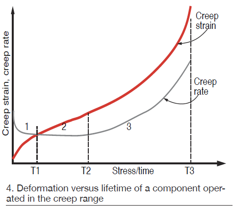
Case studies explained the stages of creep graphically in Fig 4:
-
- Creep rate is high in first stage.
- Creep rate is linear in secondary stage.
- In third creep stage, there is an exponential behavior of creep strain. Cause is the formation of micropore chains.
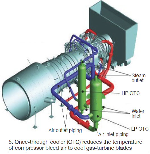
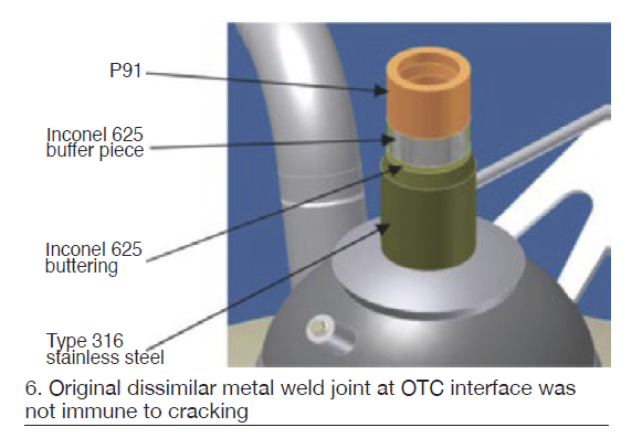
Once-through GT coolers. Alexandros Antonatos, Public Power Corp, Greece, discussed once-through coolers for Alstom GT24 and GT26 engines. The water-cooled heat exchangers reduce the temperature of compressor bleed air for cooling critical parts of the gas turbine; steam is produced in the process (Fig 5). The steam outlet is Type 316 stainless steel transitioning to P91, therefore requiring dissimilar metal welds or a combination of mixed weld seams.
Operational stresses, including demanding steam parameters, contribute to high stress in the weld joints. “Weld-crack incidents at various sites worldwide have been reported in this transition zone,” he stated.
Antonatos presented various dissimilar-metal weld joints being used in an effort to avoid creation of these cracks. In its original configuration, the transition included an In625 buffer (Fig 6). But after a few years of operation, cracks were reported.
A suggestion was to choose a location with lower system stresses (a vertical pipe section) and provide a gradual transition with 6-in. bridging pieces (Fig 7). However, cracks appeared in this “new” design at one of the weld joints.
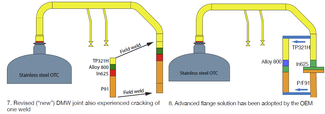
The latest design features Alloy 800 between the In625 and TP321H segments, joined by three dissimilar-metal welds, to form a so-called “advanced flange solution” now offered by the OEM (Fig 8). The speaker said the flange has not yet been installed in the field.
Maintenance forecasting. Martyna Tomala, Silesian University of Technology, Poland, offered a review of coal-fired 200-MW units in Poland, and the effects of operational changes as they adjust to renewables. She focused on steam turbines. Prevailing concerns are turbine-blade erosion, corrosion attributed to shutdown practices, increased crack propagation (first rotor failure scenario), and low-cycle fatigue (second rotor failure scenario).
“Crack propagation is one of the most dangerous processes in the turbine rotor,” she explained. “The most vulnerable area is the turbine central bore. FEM (finite element method) analysis allows determination of stresses occurring in the rotor during startup and steady-state operation (under creep conditions).”
She explained the components of stress during heat-up and creep relaxation. Calculations were presented for three operating scenarios with these assumptions:
-
- Rotor service life, 20 years.
- Operation time, 6000 hr/yr.
- Number of annual starts, 200.
- Steady-state operation time between starts, 30 hours.
Crack propagation rates were shown based on the Monte Carlo Method (repeated random sampling to obtain numerical results). Fracture toughness was determined using nondestructive small punch tests. This led to preventive activities planning based on avoided-risk criteria.
A highlight was a detailed explanation of net present value (NPV) sensitivity analysis, leading to optimization of preventive activities and intervals, as well as cost impact.
Also in Session 5 were the following:
-
- Stress corrosion cracking in T24, VGB PowerTech, Germany.
- Hardness methodology for creep deformation and residual life, Toshiba, and Tokyo Institute of Technology, Japan.
- Creep degradation in reformer tube after 17,000 hours at 980C, TNB Research et al., Malaysia.
- Creep life estimation by crystal misorientation frequency distribution, Nippon Steel, Japan.
- Development of oxide scales on inner and outer surfaces of reformer tubes, TND and Petronas Berhad, Malaysia.
In Session 6, various presenters concentrated on risk-based investigation methods and stress analysis. This included finite-element (FE) analysis of stress fields in steam pipeline components, from the school of mechanical and design engineering, University of Portsmouth, UK.
This particular presentation included residual stress analysis of pipe bending through an FE model for bending simulation, verified by published data. Featured was field-structure interaction (FSI) using ABAQUS.
Models presented simulated the pipe bending and fluid structure interaction at the pipe elbow. Further work is required to correctly capture precise stress fields in pipe under high temperatures.
In another presentation, ETD’s Feroza Akther discussed risk-based maintenance and performance optimization of powerplants. Examples were taken from a recent study for a client in Canada. Planned maintenance was suggested in three categories: preventive, predictive, and proactive.
A section on recent developments in smart analyses of equipment performance included SmartCET, a corrosion monitoring technique developed by InterCorr International (Houston), now part of Honeywell Inc. Smart thermal scanning and digital radiographic techniques were also presented.
This detailed presentation ended with the following list of common aspects for a best-practice risk management procedure:
-
- Assess credible hazards for threats to equipment based on plant experience and equipment knowledge.
- Identify failure modes and potential causes.
- Determine probabilities and resulting impacts.
- Set risk treatments or mitigation measures.
- Assign a measure of risk to each item.
- Define acceptable or tolerable risks.
- Combine risk with inspection history to determine future inspection intervals and methods.
Also presenting were Best Material Co and IMC Co of Japan discussing new software for the execution of boiler risk-based investigation; modeling of grain-boundary cavitation and rupture by the school of computing and engineering, Univ of Huddersfield, UK; and the benefits of RCM implementation in power generation by ETD.
Wrap-up. Prerecorded sessions also were integrated into the meeting. They covered Type IV failure in 9Cr weldments; defect assessment with ETD’s Crackfit technology; creep rupture modeling of P92 by grain-boundary cavitation; calibration of creep cavitation modeling for 316H steel; creep cavitation by cavity histogram; and creep damage constitutive equations.
The online sessions were chaired by EMPA’s Holdsworth and ETD’s Shibli, Akther, Robertson, and Dr David Allen.
The conference concluded with a one-hour discussion session where all participants could switch on their videos and participate. This was a very positive feature with attendees able to see other participants and ask more questions.
Based on the success of the two-day virtual conference, ETD is organizing the following three online events in early 2021:
1. A two-day Boiler Life Assessment Training Course in February.
2. A three-day event focused on high-temperature defect assessment in April. This will be the eighth in the series of triennial HIDA conferences covering high-temperature plant component failure, cracking, damage, and condition/life assessment.
3. A four-day course on gas turbines.

Dogwood Energy Facility
Owned by Dogwood Energy, City of Independence, Missouri Joint Municipal Electric Utility Commission, Kansas City Board of Public Utilities, and the Kansas Power Pool
Operated by NAES Corp
650-MW, gas-fired, 2 × 1 combined cycle located in Pleasant Hill, Mo
Plant manager: Steven Hilger
Sticking to a site map

Challenge. In the 17 years prior to implementation of its Confined Space Map, Dogwood had several occasions where a lock-out/tag-out (LOTO) involving a confined space was cleared, but remained open. After an HRSG door was left open following an outage, the plant started looking into ways to eliminate the potential for a recurrence, having to track over 150 confined spaces at the plant.
Solution. CRO Michael Davis, a member of the Safety Committee, had advocated for a visual way to account for confined-space status in the control room. After reviewing different ways to track confined spaces, he noticed that most of the solutions relied on technology that increased both cost as well as the CRO’s workload. He focused on finding a low-risk, low-cost, low-technology, high-results outcome.
His idea was to create a site map showing the major equipment and some of the underground systems on a white magnetic board that included all the plant’s confined spaces. This map would be installed in the control room above the LOTO cabinet.
Davis worked with NAES drafting to develop a simplified site plan for the plant. In addition to the major equipment and underground information, the 45 × 45-in. map also includes the following:
-
- Safety showers in green.
- Tornado shelters.
- Water storage tanks and capacities.
- Manholes with system identification and numbers.
- Electrical manways.
- Hazardous chemical locations.
For work requiring a confined space, the CRO moves the magnet label for the associated confined space from the label storage board, at the right in Fig 1, to the site map’s left-hand side and then places a red magnetic dot at the location of the confined space on the site map (Fig 2). This provides personnel at Dogwood with a visual of the approximate location of open confined spaces at any given time. After a confined space has been closed and returned to its normal state, the label and dot are removed and returned to the storage board. Keeping the process simple helps its success.

The map also provides a visual representation of the plant to facilitate discussions among plant personnel and contractors, and to show evacuation routes and muster points, and all door swings.
Results. The Confined Space Map has been in use for more than a year. Dogwood personnel believe it has resolved the issue of leaving confined spaces open when they should be closed. In addition, the site map has provided the plant a good visual for discussions with contractors by identifying the locations of equipment and various underground manhole connections and safety showers. This is a safety and awareness win for the employees and contractors.
Project participants: Michael Davis, Eric Smith, Monty Ross, Jim Feitz, Mary Baptista, Steven Hilger.
Working safely on the package roof
Challenge. O&M personnel have a routine need to perform maintenance and inspections on BOP equipment located above the gas-turbine mechanical package. Access to this equipment required personnel to either climb an extension ladder or climb over railing from the GT access platform. Once on the roof, fall protection was required for the duration of work, restricting mobility. When multiple individuals were working on the roof at the same time, fall protection was more complex.
Solution. Dogwood worked with local firms to design and install an access point and handrail system to allow personnel to work on top of the mechanical package without the need for fall protection all the time (Fig 3).
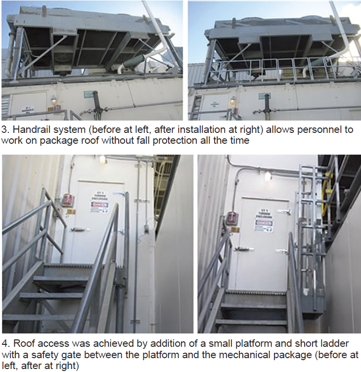
The easiest part of the project was to give personnel access to the mechanical package roof by adding a small platform and short ladder with a safety gate between the GT access platform and the mechanical package and by adding railing to three sides of the area (Fig 4).
The most difficult part of the project was determining the best way to allow forklift access to the roof to transfer equipment while still providing a system to minimize the need of fall protection when working on the mechanical-package roof. While Dogwood would have preferred a prefabricated swing gate for forklift access, a custom design was required to accommodate the plant’s configuration.
When removal of large equipment is required, personnel don their fall protection PPE and tie off before removing sections of the front handrail to allow access. Sleeves were installed on the mechanical package roof to allow for storage of the removed handrail sections during these evolutions. Safety signs were added to each handrail system reminding personnel that fall protection PPE is required when the handrail system is removed.
Results. Dogwood completed installation of the hardware on both GT mechanical packages in December 2019. Personnel performing work on top of the packages now have safe access to the roof and a handrail system to eliminate the need for fall protection during most work.
By eliminating the need for fall protection during most work, personnel have better mobility and more unrestricted access to the equipment located on top of the mechanical package and do not need to worry about tripping over fall protection lanyards.
Project participants: Chuck Berg and Steven Hilger
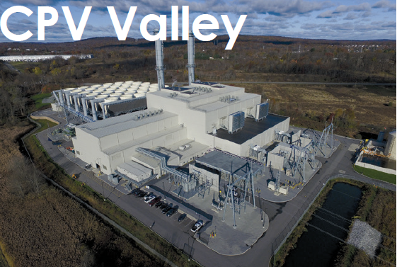
CPV Valley Energy Center
Owned by Competitive Power Ventures and Diamond Generating Corp
Operated by DGC Operations LLC
680-MW, gas-fired, 2 × 1 combined cycle located in Middletown, NY
Plant manager: Ben Stanley
Planning, collaboration key to outage management process
Challenge. IPPs with minimal staffing must be flexible and tactical when planning all outages. Utilizing a standardized (but adaptable) process for planning and execution helps keep employees and contractors safe and surprises to a minimum.
Solution. The plant’s O&M team works closely with asset-management staff, third-party support, and equipment OEMs to plan and execute outages. Key elements to the program are:
-
- An outage planning procedure that outlines the process for the team. This procedure is reviewed by the team before any upcoming outages.
- An outage summary document that states the purpose of the outage, the intended worklist, EHS planning, third-party participation, logistics, training, cranes and rigging, etc. It provides a narrative or “story” of the outage and evolves over time as the team refines the plan and gathers more detailed specifics around the work needed.
- A checklist that details the main components of the outage. Starting with the type of outage (routine, minor, CI, HGP, major) and expected duration, the planning checklist includes the following:
-
- Internal meeting schedules—including those for LTP/LTSA service planning, EHS planning, budget reviews, and meetings with third-party vendors.
- Outage-date requests and approvals to energy managers and ISO organizations.
- Outage project list, which comes from the work-management process in the CMMS. Work orders and PMs are appropriately identified, prioritized, and classified for each type of outage. This list is reviewed continuously during the routine work-management process (backlog and work planning meetings).
- A preliminary outage schedule is developed and shared with stakeholders early in the process. Critical-path items are identified and highlighted.
- Work schedules. Operator/maintenance crew shift schedules are reviewed and updated. Shifts are added where needed to support plant evolutions, EHS activities, operator training, etc.
- Special compliance inspections needed (pressure vessels, insurance/risk inspections, compliance metering).
- Rigging and lifting. A review of the need for lift plans and special rigging certifications is performed. In some cases, rigging/crane certifications require long lead times with third parties.
- Safety planning and third-party support (confined-space rescue, audit support, and site security).
- An EHS plan for the outage details items such as hazardous waste generated, inspection and audit planning, potentials for high-risk environmental issues, etc.
- Logistics. Parking, laydown, deliveries, additional office space, etc, are reviewed and an updated site map is generated.
- Budget and procurement. The business-administration and asset-management teams are fully integrated into the process with a detailed list of parts/inventory needed, executed contracts, purchase orders, and appropriate delegation of financial authorities. The team also maintains awareness of the potential for additional discovery work and prepares to communicate variances as they occur during the outage.
- In-house parts inventory is reviewed. Long-lead-time items identified should be ordered well in advance.
- Severe-weather contingency planning includes a review of forecasts, historical weather patterns, and lessons learned. Focus is increased on personnel safety during severe weather. Consideration is also given for activities such as water washes during freezing ambient temperatures, delays in deliveries during extreme weather events or snowstorms, emergency lodging/hotels, etc.
- Plans are developed for pre-, in-, and post-outage testing. Bear in mind that several tests are best performed during shutdown to minimize reliability risks (turbine auxiliaries, overspeed testing, fuel swapping, etc). There are other tests that should be performed only when the plant is offline. Finally, certain validation testing is performed during the restart process.
- NERC task review of the required compliance testing items is performed for NERC applicability.
- An integrated checklist is developed for critical site and contractor contacts. Since this changes for each outage, it’s important for staff to update the list specifically for each outage.
- External notifications. Regulators, emergency management organizations, and in some cases local government agencies, require notifications. Best practices have been adopted to make courtesy notifications to town supervisors, boards, mayors, etc. This prepares them for increased traffic in the area, additional vehicles parked onsite and potential inquiries from the public/media.
- Scope freeze. The O&M and asset managers determine the appropriate date for scope freeze so that no additional work items are planned for unless they fall under a higher amount of scrutiny by plant management. This helps to minimize schedule impacts.
- A lessons-learned meeting is conducted shortly after outage completion. Focus is on both when and where improvement is needed. As many stakeholders as possible are invited to the session. The list generated helps to create corrective actions and items to consider for the next outage. Continuous improvement is the goal.
-
-
- Final outage report includes the outage summary, detailed schedule, facility outage map, detailed costs and variance report, and final results of the work list.
Results. The collaborative efforts of the team lead to safe, well-planned, cost-effective, and well-documented outages. Utilizing the procedures and tools developed by the team helps to ensure that the outages are completed on schedule and on budget with minimal surprises.
Project participants: The entire O&M staff, including Donald Atwood, Ben Stanley, Ed Peters, Dave Engelman, Tanya Rovner, Josh Zimmer
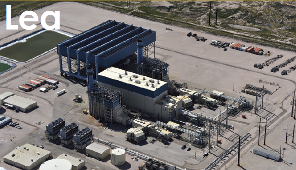
Lea Power Partners LLC
Western Generation Partners
Operated by Consolidated Asset Management Services
604-MW, gas-fired, 2 × 1 combined cycle located in Hobbs, NM
Plant manager: Roger Schnabel
Duplex lube-oil filter installed on BFP-skid fluid drive
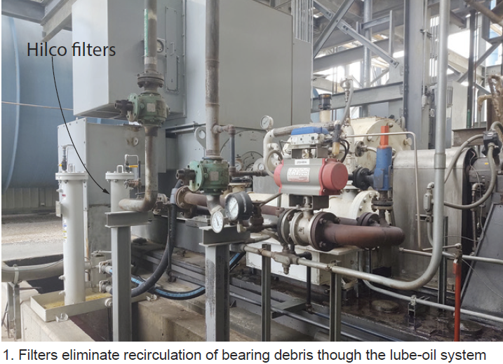
Challenge. Under the original design, debris from any failed bearing in the system would be collected in the fluid-drive sump and then circulated through the system. This would cause damage to other bearings. Of particular concern was the debris that would accumulate inside the dead zones of the shell-and-tube lube-oil coolers. The design of those heat exchangers made them difficult to clean after a bearing failure. Debris hidden in the coolers would circulate onto the new bearings and cause premature failures.
Solution. Adding a set of duplex filters after the pumps and before the lube-oil coolers eliminated recirculation of bearing debris through the system (Fig 1).
Results. After an upcoming overhaul, the heat exchangers will be cleaned thoroughly. They will remain clean because lube oil now is filtered. Even if a bearing failure were to occur, debris from that failure would be removed by the filters and not get into the lube-oil coolers. This will increase fluid-drive reliability and increase bearing life.
Duct-burner fuel-skid shut-off valve leakage test retrofit
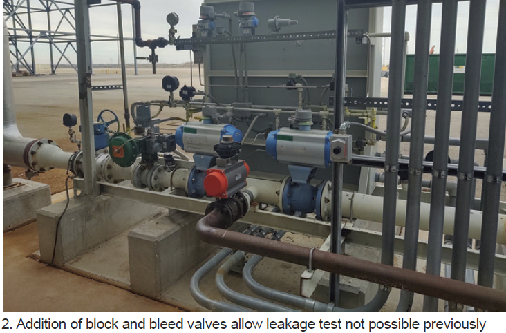
Challenge. The duct-burner control system wasn’t designed to allow operators to leak-test valves in the fuel-gas system. The leak test is an insurance-company requirement.
Solution was to add a block valve between the last block valve and the duct-burner distribution manifolds, plus a bleed valve, vented to a safe location between the two block valves (Fig 2).
Results. The system now can be isolated from the duct-burner manifolds and tested for leaks. A leak test was performed during a recent outage and satisfied insurance-company requirements.
Redundant filter system for ammonia injection skid
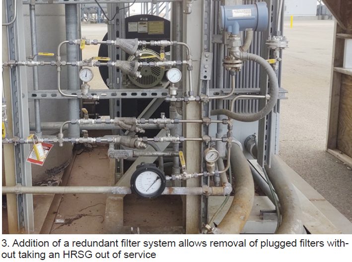
Challenge. The original design had a filter before the single valve controlling ammonia flow to the HRSG. Debris from the ammonia tank would collect in the tubing and plug the filter. An outage was required to correct this problem each time the filters clogged up.
Solution was to add a second filter in parallel to the original one with all the required block valves, drain valves, and pressure differential gages, thereby enabling one line to be taken out of service without stopping ammonia flow to the HRSG (Fig 3).
Results. After this modification was completed, the second filter was placed in service and blocked off. Once the filter in service shows sufficient pressure differential, the standby filter is lined up. Thus, a filter can be changed-out without taking an HRSG out of service.
Redesign HRH bypass steam diffuser in the ACC duct
Challenge. The hot-reheat bypass diffusers in the air-cooled-condenser duct were failing regularly. The diffusers were fabricated of ½-in. plate in two sections with ½-in. holes totaling 50-in.² of flow area. The holes were very close together (Fig 4) and a combination of flow and vibration would break the metal between the holes. In the first 10 years of plant operation these diffusers had failed twice.
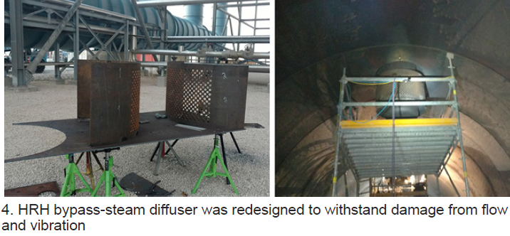
Solution. The solution was to redesign the diffuser area, using the same ½-in. plate but drilling 1-in. holes on 2-in. centers for the same total flow area. This increased the distance between holes and therefore making the entire diffuser much stronger to withstand the flow and vibration.
Results. Following the installation of the newly designed diffusers, the ACC duct was inspected after about four months of operation. The diffusers showed no damage or cracks. Plant personnel plan to monitor diffuser condition whenever the opportunity exists.
Flowmeter installation on the air-ejector steam line
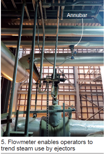
Challenge. As designed, the plant didn’t have a flowmeter to measure the amount of steam used by the ACC air ejectors. This made it difficult to evaluate ejector performance.
Solution was to install an annubar in the steam line common to all the ejectors (Fig 5).
Results. After flowmeter installation, the plant was able to trend steam use by the ejectors during startups and normal operation. Flow measurement has helped in the troubleshooting of ejector issues that could not have been diagnosed previously.
Upgrade heat-trace control panels to alert CRO with DCS alarm
Challenge. Heat-trace control panels (HTCP) supplied with the plant included individual breaker-condition indicator lights on the front of the panel for local indication of a problem. During cold-weather operation, plant operators were making frequent rounds to verify there were no tripped breakers on the HTCPs that could lead to plant reliability issues caused by frozen instrument sensing lines.
Solution. Install new cable runs from HTCPs to the control room DCS. Wire the relay board to create an alarm series circuit such that if any breaker trips an alarm is generated on the DCS. In addition, create new alarm points and graphics screen on the DCS (Fig 6).
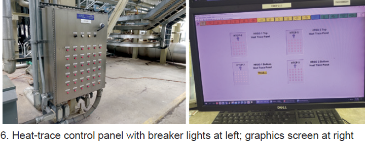
Results. After the HTCP remote alarms were implemented, the incident rate of frozen transmitter sensing lines was reduced by early detection which allowed faster corrective action. The HTCP DCS alarm functionality has improved overall facility cold-weather reliability.
Project participants: Roger Schnabel, Carlos Sanchez, Richard Shaw, Kelvin Mendenhall, and Tyler McCoy
Monroe Power Co
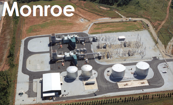
Owned by Southeast PowerGen LLC
Operated by Cogentrix
380-MW, gas-fired, two-unit, simple-cycle plant located in Monroe, Ga
Plant manager: Mike Spranger
Turbine-enclosure ventilation-system upgrade
Challenge. During a test run following a planned maintenance outage, one unit experienced a fire-system high-temperature trip in the turbine enclosure which caused a turbine trip. One of the contributing factors to the fire-system trip was that the turbine enclosure ventilation system did not respond to the rising temperature fast enough.
Solution. Staff designed and installed upgraded ventilation system controls. The thermostats by the door were replaced by RTDs mounted on the ceiling so that the ventilation system is operating based on the hottest areas in the turbine enclosure. Louvers operate independently from the fans at a lower-temperature setpoint, allowing heat to escape naturally and reduce the stress on fans and motors. A ventilation graphics screen was added to the DCS so a control room operator can monitor and operate the system remotely.
Results. The ventilation upgrade, completed for less than $500 per unit, improves the operation and reliability of the gas turbines.
Project participants: James Goins, Chris Harris, Scott Hobbs, Charles Gibson, Nick Sanz, Bly Crane.
USEA 17th State of the Energy Industry Forum
 With a somber undertone from the recent death of its long-time leader, Barry Worthington, the United States Energy Association (USEA) held its 17th State of the Energy Industry meeting virtually on Jan 28, 2021, less than a week after President Biden was inaugurated. Executives from 22 separate beltway policy and advocacy organizations offered their glimpses into the next four years under a Biden administration and a razor-thin Democratic majority in Congress.
What was most revealing, however, had nothing to do with the actual presentations. The last speaker, Heather Zichal, represents the brand new American Clean Power Assn (ACPA), an umbrella group pulling together solar, wind, storage, and transmission interests, so that the “trillion dollar renewable energy industry,” in Zichal’s words, can speak as one voice. We “need a deeper bench of Republican support for clean power and renewables,” said Zichal, a bigger “coalition of the willing,” for the transition to the clean energy economy.
By contrast, more than one-third of the organizations represented were associated with natural gas, six with gas in their name, one which qualifies if you make the largest component of natural gas (methane) into a alcohol (methanol), and one representing petroleum companies, almost all of which are also natural gas companies.
It seemed pretty clear which energy industry interests have acted to stand in “unity,” a word Biden used over and over on the campaign trail and continues to use, and which appear fragmented.
Generally, these types of events are polite affairs laced with diplomatic, optimistic language about working with the new elected officials. If there was going to be an exception, one might suspect the coal group. But no. Mike Sommers, American Petroleum Institute, declared a “posture of strong opposition” to the Biden administration, seeing no “unity” in his early actions, most notably shutting down the Keystone Pipeline.
On the other hand, Rich Nolan, National Mining Assn, lauded the US mining industry as “on the cusp of a rebirth. Mining policy is energy policy,” he said, referring to the soaring demand for metals and minerals critical to the renewable and non-carbon energy supply chain. Betsy Monseu, American Coal Council, forecasted that the natural-gas share in electricity will decline 41% in 2021 and another 8.9% in 2022 because of price increases, and that coal is essential to “balance uncertain loads with uncertain supply.”
Julia Hamm, Smart Electric Power Alliance, gave one of the more startling stats: The number of electric utilities with net-zero carbon commitments by 2050 increased from 18 last year to 39 this year. What better evidence is there that “elections have consequences?”
One issue that clearly concerns the electricity natural-gas interests is fugitive methane emissions from their infrastructure. Thomas Kuhn, Edison Electric Institute, noted his group’s initiative to monitor methane emissions, one he called “important.” Karen Harbert, American Gas Assn, also pointed to a “new framework for measuring and reporting methane emissions.” Charlie Riedl, Center for LNG, noted his members’ principles for enhanced measurement and reporting of methane, and that conversations around methane “are increasing.”
API’s Sommers pointed to earlier success reducing methane emissions by 70% “in the largest oil/gas producing regions,” as did Harbert, who claimed that methane emissions have been reduced by 73% from the country’s natural-gas distribution networks.
Not surprisingly, the most prevalent theme was the need to up federal money for more RD&D and commercial investment:
-
- Kuhn, “We need lots more R&D.”
- Sommers, “. . .need more investments in American oil and gas.”
- Nolan, “need to advance technology for the fuels the world has to offer.”
- Arshad Mansoor, EPRI, the nation “must make a commitment this decade to negative emissions technologies.”
- David Carroll, Gas Technology Institute, “many of the technologies needed to get to a no-carbon 2050 don’t yet exist” and “federal energy innovation spending is 10% that of defense innovation spending.”
- Monseu, the National Coal Council has been involved in carbon capture, utilization, and storage (CCUS) for many years. Biden included CCUS in his campaign, and robust funding for CCUS is a big part of the Energy Act of 2020 (passed during Congress’ lame-duck session).
- Jim Matheson, National Rural Electric Cooperative Assn, “We need an infrastructure program at the federal level.”
My job is better than yours. Jobs and economic activity didn’t get the attention one might have thought, perhaps because most speakers were more consumed with getting through the COVID-induced economic fallout. Derrick Morgan, American Fuels & Petrochemical Manufacturers Assn, did make the case for why a petro job is better than a renewables job. Each job in his industry, he said, supports 32 others, 16 directly and 16 induced. His observation was a counter of sorts to the Biden administration ambition to retrain fossil-fuel workers for opportunities in the renewables sector.
Maria Korsnick, Nuclear Energy Institute, reminded everyone that nuclear power plants are the largest source of carbon-free electricity, and “uniquely reliable.” While NEI lauded the recent NRC approval of the first small-reactor design, the organization seems more focused on saving existing reactors from political threats at the state level.
Lest any in the CCJ community think small reactors are a threat to their business, the timeline from an NRC-approved design to a permit to construct (along with the commercial investment) is long and arduous, based on recent experience with the advanced light water reactors. Better to worry about the goal set by ACPA’s Zichal: 50% renewables on the electricity grid by 2030.
GTI’s Carroll acknowledged the “cycles of hype” with the “hydrogen economy,” dating back to the 1960s. But, he said, “this time it’s different,” adding “famous last words, right?” He identified several H2 projects GTI is involved with, notably a broad infrastructure integration study for Texas, in which wind power is used to produce H2 for transport and delivery through existing pipelines.
Finally, Fred Hutchinson, LNG Allies, tempered the net-zero-by-2050 enthusiasm with a reminder that there is expected to be 2-billion more people on earth by 2050, the world will need 50% more energy by then, while 850-million people still lack access to electricity.
Therein lies the conundrum for the energy industry in the aggregate: The affluent want less carbon as soon as possible; the less affluent want more energy now.
If your site has a pre-F-class gas turbine, in peaking or combined-cycle mode, and you think there’s more money to be had playing the spot-capacity or flexible-start markets, take an hour and listen to TTS Power’s recorded webinar below conducted a couple of weeks ago. Chances are, you’ll come away with an option that not only makes sense but also is affordable.
For optimizing capacity to meet the spot market, the options include raising firing temperature, increasing mass flow, implementing dormant peak-firing capability (that is, originally designed into the unit but not used), and optimizing peak firing (especially for DLN units). Most of these require a thorough evaluation of the unit’s current operating regime compared to original design. It can be as simple as discovering that the current firing temperature is what satisfied the commissioning criteria, not the GT’s capability; or as complex as learning that mods deployed to increase mass flow (wet compression, for example) did not properly optimize for firing temperature.
The key, noted Ricky Morgan, TTS Power’s VP engineering, during the Q&A, is to ask yourself, “where could this machine fire,” not assume that where it currently is firing is optimum.
Only a few vintage GT designs can meet 10-min start requirements without mods, noted VP Pat Begley. The biggest gain comes from eliminating the purge cycle via NFPA 85, but smaller gains—such as by upgrading wiring and cabling, replacing hydraulic/pneumatic valves with electric, eliminating single points of failure in transmitters, sensors, and switches, upgrading HMI, and otherwise replacing obsolete components—can add up.
The impact of any of these mods on GT maintenance factors and the site’s emissions permit must of course be thoroughly evaluated. Plus, the more “vintage” a machine is, the more likely it is to be operating off of original design, if only because of deferred maintenance and component changes. Thus, you’ll want to have a site evaluation study once you identify one or more options that could make sense.
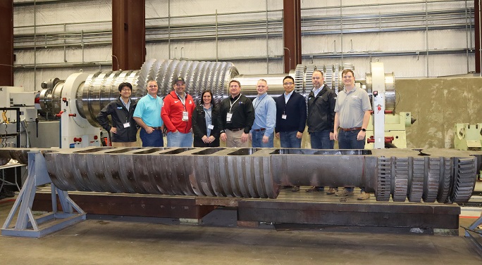
Doosan Turbomachinery Services personnel present a new, replacement 11NM gas-turbine rotor to key staff from the customer, Midland Cogeneration Ventures (MCV), which now has three new rotors in operation with no issues reported. Another engine at the 12-unit site will receive a new rotor in the spring, yet another in the fall. Current plan is to extend the lives of three rotors removed via refurbishment.
Keep up with these projects by participating in activities sponsored by the Alstom Owners Group (AOG). Doosan’s Sangjoo Lee will be presenting on this and other relevant projects for the group on Tuesday, March 2, from 10:00 – 10:30 EST. The virtual conference runs March 1-5 and is open to all powerplant owner/operators. Register here at no cost.
In the photo, from left to right, Sanjoo Lee, DTS performance excellence director; Bryan May, DTS account manager; Adam Johnson, MCV staff engineer and gas-turbine SME; Kristi Gledhill, MCV’s supply chain manager; Brian Vokal, VP operations for MCV; Dan Tenbusch, MCV’s maintenance manager; Sean Choi, DTS CSO; Glenn Turner, VP engineering for DTS; and Alex Ford, DTS rotating equipment engineer.
User-group meetings afford the opportunity to expand your knowledge of gas and steam turbines, and generators, and their controls, auxiliaries, etc. Virtual conferences on these topics are especially convenient and economical for staff training. They allow participation by everyone in the plant, not just the select few who would attend an in-person meeting. The best part: No charge for the education.
 Presentations by Arnold Group at the 501F Users Group meeting last week, and at the upcoming Alstom Owners Group (AOG) meeting (March 1-5), illustrate the level of detail you can expect from most vendors discussing their areas of technical expertise.
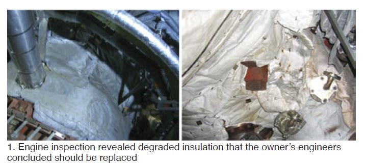
It’s possible to learn a great deal by simply listening. Consider your turbine’s insulation system—an afterthought at many plants until the package temperature exceeds best practice, someone inadvertently comes in contact with very hot metal, etc.
-
-
- How would you inspect your unit’s insulation to determine if it is beyond its useful life and replacement with an upgraded system would improve both performance and safety?
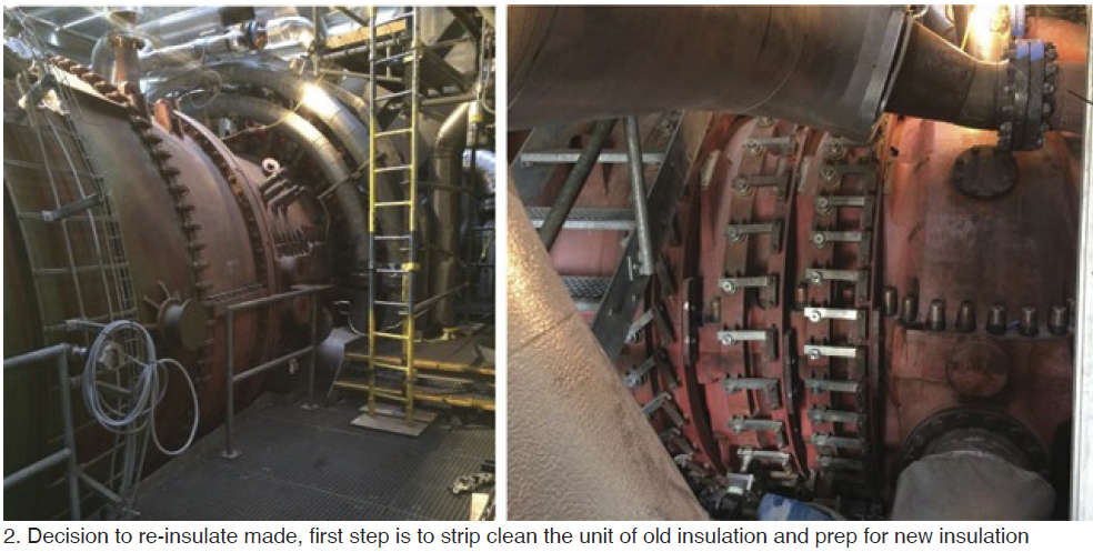
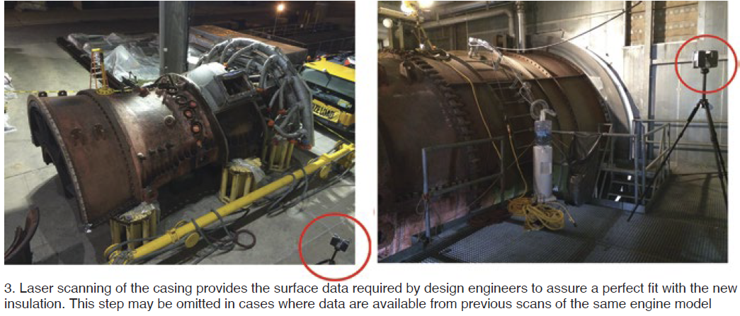
- What are the key steps in the replacement process?
- How long does the project take from inspection to determine current condition to restart after installation?
-
You’re sure to have other questions as well—most of which can be answered during the Q&A session after the presentation or when visiting the supplier’s virtual booth at the end of the conference day.
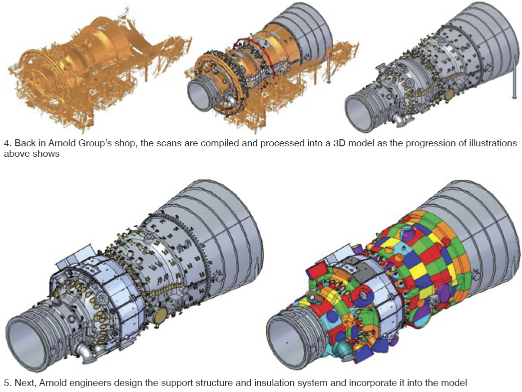
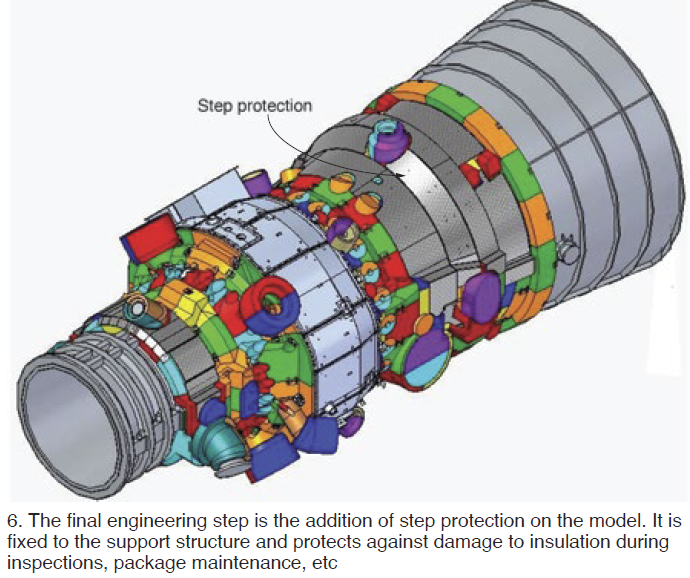
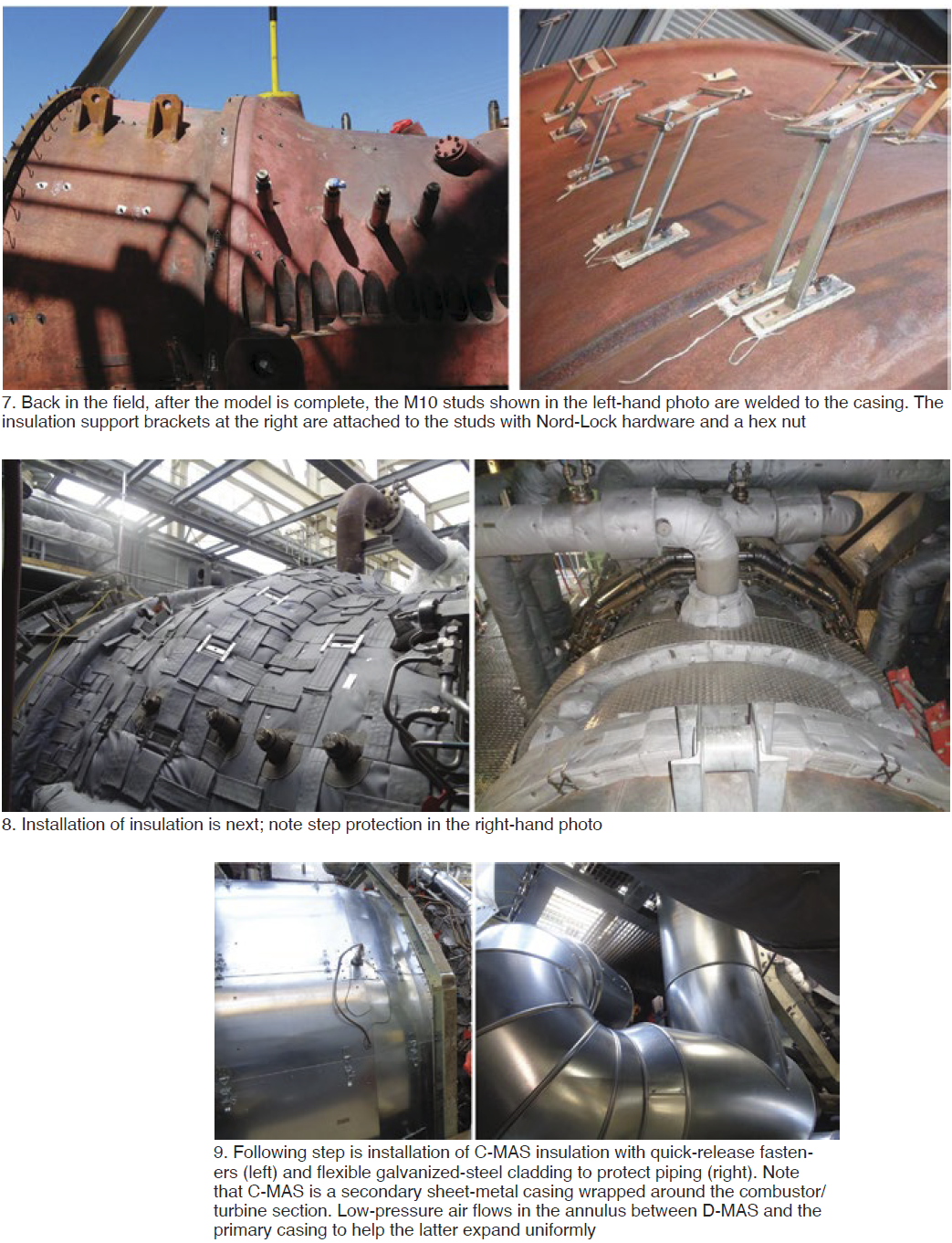
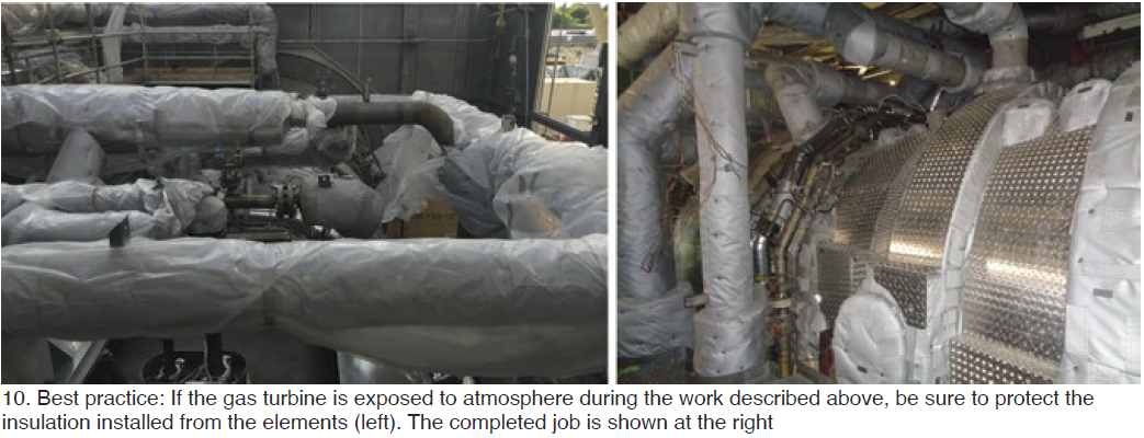
The photos below walk you through the re-insulation of a GT24, a process similar for all frames. Spending a few minutes looking at the images will likely raise questions in your mind about things you want to know more about to make better decisions for your plant in the future. Pierre Ansmann will be presenting for Arnold Group at the AOG conference. Listen to him in the 7:30 to 8 a.m. time slot on Thursday, March 4.
Replacing turbine insulation—a 10-step process
Variety of extended learning opportunities for powerplant end users
One of the distinguishing characteristics of annual meetings hosted by the Alstom Owners Group is its training courses. This year’s program, outlined below, features seven two-hour training sessions on Friday, March 5—all starting at 10:00. A good strategy might be to select the topics of greatest interest and assign plant personnel to monitor each of those sessions; then gather in the break room for a roundtable discussion of the highlights, best practices, lessons learned. Register today at no cost.
Here are thumbnail descriptions for each session:
Gas-turbine condition assessment, Doug Nagy, Liburdi Turbine.
Hot-section capital parts are life-limited and require periodic replacement. The repair versus replacement decision is an age-old debate containing facets of risk, technical, commercial, and schedule. Regardless of the decision, capital-parts condition upon delivery has a significant impact on gas-turbine reliability, efficiency, and availability. To verify suitability for service, engineering has a role to understand the manufacturability of new parts and the repairability of used parts. This presentation will help you understand the limits of what can—and cannot—be done based on condition assessments. Numerous real-world examples of the good, bad, and ugly are included.
Recubrimientos contra la corrosion y la oxidation a altas temperaturas para components de turbinas a gas, Miguelina Curcio, Liburdi Turbine.
Esta charla está orientada a que el participante visualice los criterios principales para la selección de un recubrimiento para proteger las partes capitales de una turbina a gas contra los mecanismos de degradación de su proceso de operación, así como, su importancia para reducir costos de reparacion y operatividad del equipo. Entre los temas a tratar, se analizaran las funciones del recubrimiento y cuáles son los principales mecanismos de degradación dependiendo de las condiciones de operatividad de la Turbina a gas . Se discutirán problemas de erosión, Oxidación, Corrosión en Caliente, fatiga térmica, entre otros y como afectan estos mecanismos de degradación en la funcionabilidad de un recubrimiento para que sea eficaz, y mantenga su estabilidad mecánica y metalúrgica durante la operación del equipo.
Introduction to gas-turbine air inlet filtration, Jim Benson, Camfil.
Goal is to provide plant personnel information about filters and their impact on turbine operation. Beyond providing basic engine protection, inlet filters can impact plant performance. Trends in filtration (increased efficiency) and plant operation (fewer service hours) will be included in the presentation. Plus, software and IoT tools that can provide operational personnel greater insight on filter selection and performance.
Industrial hydrodynamic bearings: Facts without friction and reliability without regrets, Dr Lyle Branagan, Pioneer Motor Bearing.
Attendees will learn fluid-film bearing fundamentals—from operational theory to damage mechanisms. Plus, the intricate details of Alstom, Brown Boveri, Stal, and ABB bearing designs. Pioneer has more than 100 years of experience to share, as well as nearly 30 years as a licensee of ABB/Alstom/GE.
Control-system training, Laurence O’Toole, Emerson.
This training will cover control principles for gas and steam turbines, with an explanation of the control functions / control loops used on modern gas and steam turbines. We will also have two additional topics of interest both for safe operation and for anyone looking to upgrade. First is an explanation on application of functional safety (SIL) lifecycle for rotation machines – what IEC 61508 standard means and a look at scope involved in implementing. Second is an update on cyber security, with new on latest industry trends and events on this area.
-
- Control principles for gas and steam turbines – how they work, control functions / loops
- Functional safety (SIL) for rotation machines – What IEC 61508 standard means and how to implement
- Cyber security for power plant installations – update and information to keep your assets safe
Long-term service agreements, what’s under the hood? Craig Nicholson, AIM Power Consulting.
The session will provide a holistic view on maintenance contracts for gas plants including the basics of contracting, pro’s and cons of a contracting maintenance strategy, when and how agreements are negotiated, as well as dissecting the key elements within LTSA’s. We will include tips and insights on how to negotiate market and risk balanced maintenance contracts for gas plants as well as a discussion on the future of LTSAs in todays cyclical variable load operating reality.
P13/BlueLine control system training, Tom Douglas, Hughes Technical Services.
Presentation is for operators, engineers, and managers who want to better understand their P13/BlueLine control system. Course covers hardware and software used to work with the system. Examples of how to follow signals through the system and logic blocks used will be discussed. Also, additional details on the speed modules, Modbus communications (serial and TCP) and fiberoptic data transfer (70DH01 and 70DH02) will be provided.
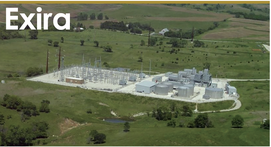
Exira Station
Owned by Western Minnesota Municipal Power Agency Operated by Missouri River Energy Services
140-MW, dual-fuel, three-unit, peaking facility located in Brayton, Iowa
Plant manager: Ed Jackson
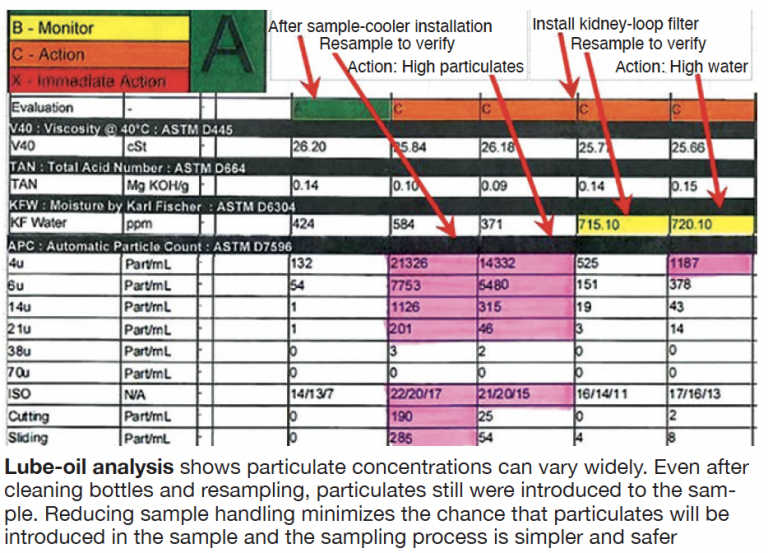
Challenge. The best place to get a representative sample for oil analysis is from the engine bearings before fluid filtration, which removes particles that you need to know are in the oil. The path of oil from the bearings of an LM6000 is through the scavenge pump, scavenge filter, cooler, and back to the oil tank. If you grab the sample from the cooler discharge, or the tank, then it is downstream of the scavenge filter and the oil you sample will be filtered.
Unfiltered scavenge oil from the bearings before the cooler is above 200F. Sampling this oil is not only dangerous because of possible burns, but it softens the plastic sample containers. One way around this is to collect the sample in a glass container and allow it to cool before transfer to the sample lab’s plastic containers. However, the more times the sample is handled, the greater the opportunity to introduce contaminants, while not lessening the chance of burns from hot oil.
Solution. Install a sample cooler. This eliminates the chance for burns, making sample collection safer, and reducing the chance of introducing contaminants into the sample; plus, it allows you to grab an unfiltered sample. A small stream of cooling water can be directed from any water source, even city water, to flow though the sample cooler while taking the sample.
Water discharged can be directed to a drain, or sewer, or recirculated back to the cooling system. For about the same amount of water as it would take to flush a toilet, you can cool the sample oil temperature from more than 200F to cool-to-the-touch.
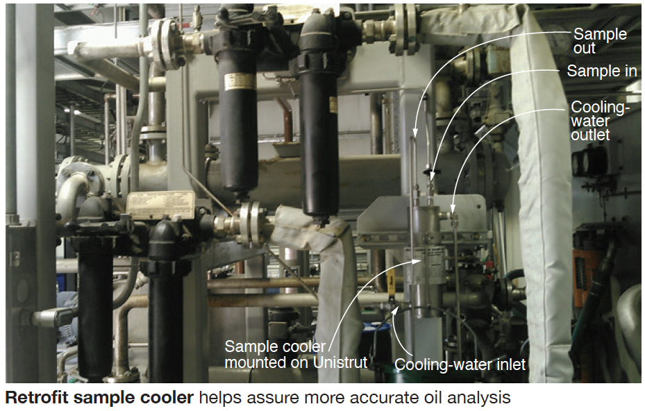
Plant personnel obtained a stainless-steel sample cooler for less than $500 and clamped it to a piece of Unistrut they added to existing tube steel on the auxiliary skid (photo). For the oil lines to/from the cooler they used ¼-in. tubing and for the water lines to/from the cooler, 3/8-in. tubing. There is an existing connection on the inlet to the scavenge cooler that is piped to the high side of the differential-pressure gage. A Swagelok ¼-in. tee was installed in this line to supply the cooler with the oil to be sampled in an afternoon.
Results. Plant personnel now obtain oil samples directly from the turbine scavenge prior to filtering, reducing the potential for an inaccurate sample caused by entry of contaminants (table). Plus, there’s a safety benefit: Reduced potential for burns from hot oil.
Project participants: Chad Case, Brendon Clancy, and Allen Scarf
