Turbine Tip No. 7 from the PAL Turbine Services solutions library applies to General Electric Frame 5, Frame 6, and early Frame 7 gas turbines equipped with Mark V control systems.
It is common for plant O&M personnel to focus their attention on the gas turbine during engine startup, operation, and loading. Fig 1 charts a variable called fuel stroke reference (FSR) from initiation of the start signal up to baseload for continuous gas-turbine operation.
It was developed from a family of algorithms embedded in the Speedtronic™ Mark V control system that program fuel flow during firing, acceleration to full speed/no load (FSNL), and ramp to baseload. GE control-system design addresses the OEM’s concerns about over-firing during startup, as well as about the rate of temperature rise and shaft acceleration.
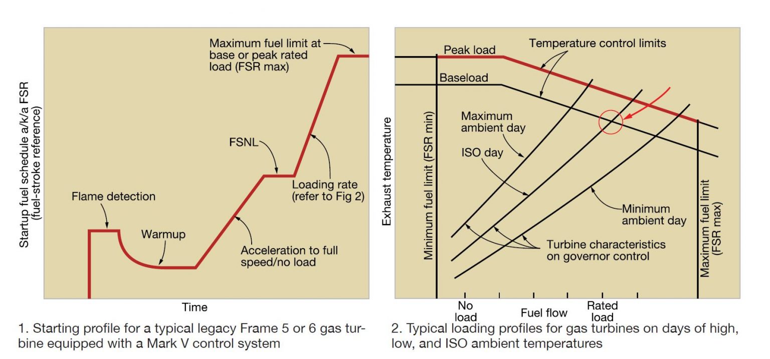
Note that it is possible to control fuel flow to less than the values illustrated should turbine exhaust temperature or shaft acceleration become excessive during startup.
The loading process from FSNL to baseload or peak power follows the demand for fuel flow according to the three curves shown in Fig 2. Since the unit is synched to the grid, speed (engine and fuel pump) has been eliminated from the algorithm used to draw this portion of the Fig 1 chart.
For simplicity, only three sloped lines are presented in Fig 2. The one to follow depends on compressor inlet temperature (T-amb) and the subsequent level of compressor discharge pressure—called CPD in today’s Speedtronic nomenclature.
Keeping the turbine under proper control by the Speedtronic system always has been of paramount importance to GE. Setting of fuel limits for fired operation is part of this and dates back to the 1950s when the Young & Franklin fuel regulator was the control device of choice.
Notice that the ambient-temperature curves in Fig 2 extend to different exhaust temperatures. However, all of these end points represent the same turbine firing temperature limit—say 2000F. In some documents, this is called turbine inlet temperature (TIT), calculated at the trailing edge of the first-stage turbine nozzle. The starting points (100% speed) take different amounts of fuel because changes in the density of ambient air affect the CPD value.
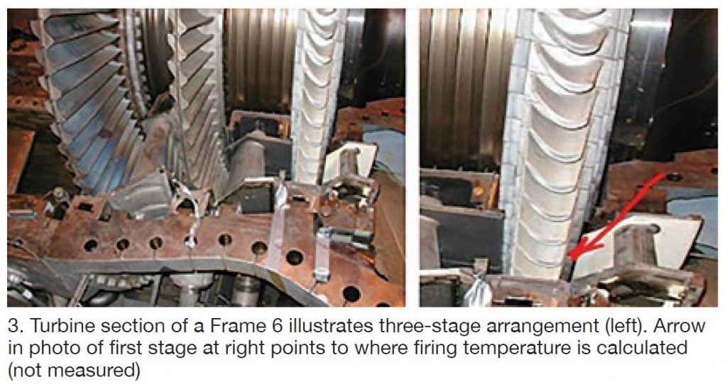
The gas-turbine controls are designed to determine, and to limit, turbine firing temperature (Tf) in the space just upstream of the first-stage buckets (at right in Fig 3); the three-stage turbine section is at the left. Note that (Tf) is not measured but rather a calculated value using thermodynamic equations incorporating CPD, Txa, and constants like the specific-heat values.
Seldom do operators pay attention to the gas turbine during shutdown processes, which can be revealing as to the general health and condition of the machine. The condition of bearings and seals, alignment, and compressor-blade clearances often is unknown. Many plant operators seem only to wait for the turbine to go on ratchet (or turning gear) for cooldown, before departing the site. Scant attention is payed to such things as these:
-
- Shutdown time. GE does not want to extinguish fuel flow immediately after the main generator breaker (52G) opens during shutdown, but rather reduce fuel flow gradually to avoid quenching the combustion and hot-gas-path components. Operators should pay close attention to the presence of flame as the unit goes from 100% to 80% speed. This takes about two minutes from circuit-breaker opening.
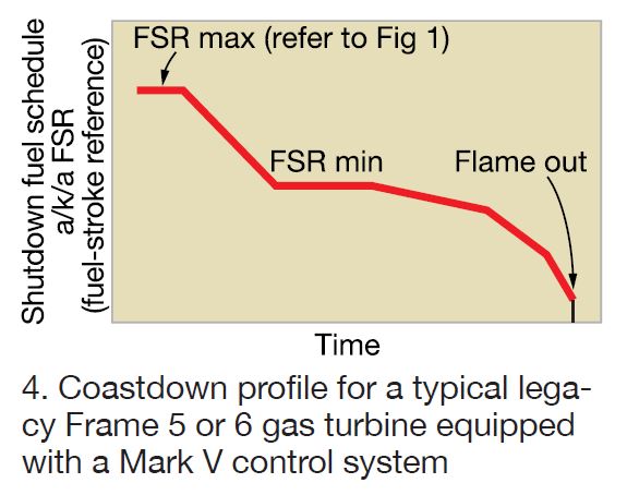 During spin down, the time to reach rotor rest after flame is extinguished, operators should remain observant. For example, attention should be directed to the time it takes for the rotor to spin freely to rest. If the shaft comes to rest too quickly, it may be indicative of tight or worn bearings, seal rubs, or misalignment of internal components. Also possible on a Frame 5 or 6B: Improper alignment of the load device with respect to the gas turbine.
- Emergency lube-oil pump (88QE) start. Does the pump turn on to assure oil flow all the way down to rotor rest? This is necessary because the main oil pump, gear-driven off the engine rotor, does not deliver sufficient oil at the proper pressure to help cool down the bearings and protect the Babbitt metal against wiping.
The emergency lube-oil pump generally has AC and DC motor drivers on the same shaft. When shaft speed drops below about 1000 rpm, the motor-driven pump takes over to provide ample cooling lubricating oil AC motor starts. If AC power is lost, the battery-powered DC motor is activated.
-
- On Frame 5 and 6B gas turbines, operators should visually confirm that the ratchet cycle has started and that the rotor is actually turning with partial strokes. For Frame 7s, operators should confirm turning-gear start and a slow rolling of the shaft.
 The COMBINED CYCLE Journal and the steering committees of the industry’s leading user groups—including 7F, 501F, 7EA, Western Turbine, Frame 6, 501G, 501D5-D5A, AOG, and Combined Cycle—collaborate to expand the sharing of best practices and lessons learned among owner/operators of large frame and aeroderivative gas turbines.
Fifty plants participated in the 2020 Best Practices Awards program with eight selected by industry experts for Best of the Best honors (see below). Details of the Best Practices submitted by all entrants will be presented in the coming months on CCJ ONsite.
CCJ launched the industry-wide Best Practices Awards program in late 2004. Its primary objective, says General Manager Scott Schwieger, is recognition of the valuable contributions made by plant and central-office personnel to improve the safety and performance of generating facilities powered by gas turbines.
Industry focus today on safety and performance improvement—including starting reliability, fast starting, thermal performance, emissions reduction, and forced-outage reduction—is reflected in the lineup of proven solutions submitted this year.
Crete Energy Venture, owned by Crete Energy Venture LLC and operated by Consolidated Asset Management Services (CAMS), is a 330-MW peaking facility located in Crete, Ill, equipped with four simple-cycle GE 7EAs. Plant Manager Brad Keaton provided these three best practices:
-
- Instrument-air reliability upgrades.
- Generator PT relocation.
- Demin-water-tank insulation.
Green Country Energy, owned by J-Power USA and operated by NAES Corp, is an 801-MW generating plant in Jenks, Okla, equipped with three gas-fired 1 × 1 combined cycles powered by GE 7FAs. Plant Manager Danny Parish and station personnel shared these best practices:
-
- Replacement of the Kato Engineering brushless exciter on a 9A4 generator.
- Safe entry into gas-turbine compartments protected by CO2 fire protection systems.
Hermiston Generating Plant, owned by Perennial Power Holdings and PacifiCorp and operated by the former, is a 500-MW gas-fired combined cycle in Hermiston, Ore, powered by two GE 7FAs. Best practices submitted by Plant Manager Brad Knight and his staff:
-
- Hydrogen purge remote activation.
- Personal ownership leads to 25 years of no lost-time accidents.
Klamath Energy LLC, owned and operated by Avangrid Renewables, is a 536-MW, gas-fired, combined-cycle cogeneration plant in Klamath Falls, Ore, equipped with two Siemens 501FD3s. Plant Manager Dennis Winn and his staff submitted these three best practices:
-
- Evaporative-cooler improvements.
- Gas-turbine fire-suppression upgrade.
- Cooling-tower cell platforms.
Milford Power LLC, owned by Starwood Energy Group and JERA Co, and operated by NAES Corp, is a 204-MW, gas-fired 1 × 1 combined cycle in Milford, Mass, powered by a Siemens 501D5. The best practice submitted by Plant Manager William Vogel and his staff describe the additions and enhancements—such as wet compression, duct burners and SCR catalyst, HP steam turbine—made to increase plant output by more than 50 MW. Note that JERA is a joint venture between two Japanese generating companies, TEPCO Fuel & Power Inc and Chubu Electric Power Co.
PSEG Peakers, owned and operated by PSEG Fossil LLC, is the name given to the simple-cycle units at Kearney (10 GE LM6000PCs), Burlington (four LM6000PCs), Linden (four GE 7EAs), and Essex (one 7EA) Generating Stations, together rated more than 1050 MW. Plant Manager Clint Bogan and his staff manage these assets efficiently using the “Maintenance and outage share file” described in their best practice.
River Road Generating Plant, owned by Clark Public Utilities and operated by GE, is a 250-MW, 7FA-powered, 1 × 1 combined cycle in Vancouver, Wash. Plant Manager Robert Mash and his team shared their experiences on the following:
-
- Non-chemical algae control.
- Combining JSAs and operating procedures.
- Lube-oil conditioning and real-time monitoring.
- Hydrogen-detection flange tape.
- Cooling-tower oil boom.
St. Charles Energy Center, owned by Competitive Power Ventures (CPV) and operated by Consolidated Asset Management Services (CAMS), is a 745-MW, gas-fired combined cycle in Waldorf, Md, powered by two GE 7FAs. Plant Manager Nick Bohl and his staff submitted these best practices:
-
- Brush maintenance program leads to increased generator reliability.
- Job status board helps keep staff informed and safe during maintenance events.
- Vision screen promotes operational excellence.
- Improving visitor tracking and management, and internal cyber controls, in complying with CIP-003-7.
- Cooling-tower fan-gearbox mod aids in monthly oil sampling and oil changes.
Other plants submitting best practices that will be shared with users are the following:
 7FA
7FA
-
- Barney Davis Energy Center
- Bastrop Energy Center
- Calhoun Power Company
- Central Eléctrica Pesquería
- Effingham County Power
- Essential Power Newington
- Hunterstown Generating Station
- Marcus Hook Energy Center
- MEAG Wansley Unit 9
- Plant Rowan
- Rathdrum Power
- Woodbridge Energy Center
Aeroderivatives
-
- Energía del Valle de Mexico l (EVM I)
- Exira Station
- Greater Toronto Airport Authority Cogen
- Lawrence County Generating Station
- Nesharim Leading Energy
- Nevada Cogeneration Associates #1
- Orange Cogen
- Orange Grove Energy
- Pinelawn Power
- Worthington Generating Station
501F
-
- CCC Tuxpan II & V
- CPV Valley Energy Center
- Dogwood Energy Facility
- Lea Power Partners
- Monroe Power Company
501G
-
- Middletown Energy Center
- New Athens Generating
- New Harquahala Generating
- Shepard Energy Centre
7EA
-
- Doyle Energy Facility
- Elwood Energy
- Lincoln Generating Facility
- Mulberry Cogen
501D5A
-
- Blackhawk Station
SGT-800
-
- Holland Energy Park
Diesel
-
- AES Levant Holdings BV
|
||||||||||||||||||||||||||||||||||||||||||
High wheel-space temperature issues were discussed by an owner/operator with three 42-MW 6Bs (Model 6581B) that had been commissioned in 2003. Two units completed their second major inspections in 2018, the third in 2019. High temperatures were noticed in the second and third turbine stages of one machine during startup following the major inspection.
The root-cause analysis (RCA) by plant personnel was thorough. The investigation reviewed the following possible causes or contributors to the issue:
-
- People: T/C installation method, installation restriction, space restriction, air filtration, and filter house.
- Equipment: damaged T/C wiring, improper installation, functionality check (yes, no, results?), T/C integrity, broken T/Cs.
- Material (HGP components): T/C source (new, refurbished?), borescope, cooling, condition of nozzles, condition of buckets, repair history.
- Measurements and seal clearances: Shroud clearances, nozzle clearances, bucket clearances, turbine clearances, diaphragms.
The findings:
-
- Wrong insertion. T/C was reading diaphragm temperature because the insertion length was incorrect. Recall the advice offered in the best practice from Part I of CCJ ONsite’s coverage of the 2019 Frame 6 meeting: Replacement of wheel-space T/Cs can be challenging. Before carefully removing the defective T/C to avoid breakage, use a Sharpie® marker to indicate the proper depth of insertion and mark the replacement T/C accordingly so you know when it’s fully inserted.
- Investigators found the T/C guide-tube cap was machined incorrectly, preventing the T/Cs from reaching the ends of their caps. When corrections were made the T/Cs installed smoothly to the correct insertion length.
Lessons learned:
-
- High wheel-space temperature is a common problem on 6Bs.
- During a major inspection, before installing the turbine casing, make sure the wheel-space T/Cs are installed correctly.
- Borescope T/C guide tubes.
- Apply heat on the T/C guide-tube caps and verify response via the control system.
- Teamwork involving all personnel with expertise to share is critical to rapid problem-solving.
The exhaust-plenum replacement case history had some twists and turns. One of the principal vendors being considered for this project emailed plant personnel the following message on a Monday morning in April 2019: Our company will be shutting its doors for business as of today. It is a Chapter 7 bankruptcy, not Chapter 11, which allows for a financial reorganization of the firm. Most employees were laid off on that day.
The week had to get better from that point forward.
Interestingly, another candidate vendor for this project, Shock Manufacturing, was formed about six years earlier by Gene Schockemoehl, who had previously been president of the company filing for bankruptcy. Turns out, Schock had a plenum design plant personnel believed more durable than that offered by the bankrupt company.
It features closely spaced, large-diameter Type-304 stainless steel pins to hold the insulation in place between the inner and outer shells of the plenum. Pins are welded directly to the outer casing where the temperature is between about 150F and 170F during operation.
Welds for the scallop-bar design offered by the bankrupt company, by contrast, are on the hot side of the exhaust casing where the temperature is more than 1000F. Frequent cycling is conducive to studs shearing off at the top of the bar and failure of the insulation system.
Rotor life extension is a topic on the minds of many 6B owner/operators because operating hours accumulate quickly in process plants that run continuously. Recall that the OEM requires inspections, refurbishment, and/or replacement of B- and E-technology rotors at 5000 factored starts or 200,000 factored hours, whichever comes first (to dig deeper, consult the latest versions of TIL-1576 and GER 3620). For most attendees at this user-group meeting, the hours limit is applicable.
The user presenting sees a 200,000-hour rotor lifetime evaluation (LTE) for his 6B without merit because the best you can do after spending all the money for the inspections, component refurbishments, new consumable parts, etc, is get approval to run another 100,000 hours (about eight years at his plant). The alternative he prefers is to bring the rotor into a qualified shop, replace all of its life-limiting components, and extend rotor lifetime by 200,000 hours.
He told the group that this course of action would involve the following at a minimum:
-
- Replace the last three or four stages of compressor wheels.
- Replace all compressor blades.
- Replace some turbine wheels and spacers.
- Replace all tie bolts and marriage bolts.
More power? Better heat rate? Faster ramp rate? FSNL in less than 10 mins? Lower load points? More Fuel Flexibility? Longer maintenance intervals? PSM will be presenting a live webinar at the 7FUG 2020 Digital Conference on June 30, entitled “What else do you need from your 7F power plants?” All GT owner/operators are able to join as many solutions are applicable across fleets.
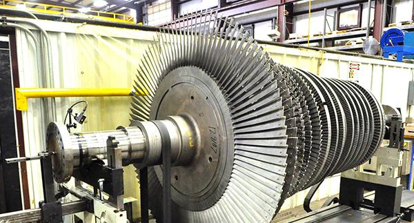
PSM’s presentation, “F6B rotor repair and lifetime extension solutions for improved lifecycle costs,” on the final morning of the Frame 6 Users Group’s 2019 conference, offered an alternative to the OEM’s LTE program described on the previous day.
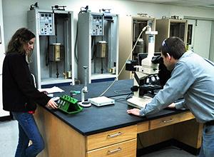
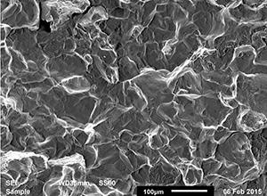
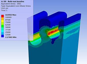
The presentation began with the requisite “who we are and what we can do for you,” shop locations, international affiliations, numbers of LTE projects completed and the frames involved, availability of seed rotors for swaps to eliminate outage time, rotor-disk manufacturing experience, computer program and analysis capabilities for modeling, materials analysis, NDT capabilities (eddy current, ultrasonic, microstructural review, etc). You can access information of interest on the Frame 6 website.
What might have been the most interesting segment of this presentation for hands-on users came at the end—recent findings.
Example 1: 7EA compressor-rotor distress was identified in multiple locations—specifically pitting in disc webs and distress in blade slots previously blended and/or cracked. FCD was said to accelerate aft slot cracking; previously blended slots re-cracked during the subsequent interval.
Example 2: Rabbet-fit cracking was attributed to improper interference between disc snaps. The speaker said PSM reviewed critical specifications and ran calculations before shop personnel were allowed to “chase out” the crack. Re-contouring of the OEM’s geometry was said to produce a life benefit.
Example 3: A 6B rotor (more than 5000 factored starts and about 40,000 factored hours) was found to have a flaw in the first turbine wheel, which was attributed to fast starting of the machine. Calculations and modeling conducted based on site data predicted the failure and suggested a material change and design refinements that would improve low-cycle fatigue life.
Example 4: Inspection of a 9E compressor revealed blade-slot cracks that had migrated through the rim. Multiple indications also were found on pumping vanes. Plus, cracking was found in the counterbore of the forward turbine stub shaft. This led engineers to believe in the possibility of component retirement during the upcoming LTE; they suggested the owner/operator develop a contingency plan.
The first presentation after opening remarks reviewed how GE communicates with its customers and the value to plant personnel of the OEM’s Technical Information Letters (TILs), Product Service Safety Bulletins (PSSBs), Product Service Information Bulletins (PSIBs), and GEKs covering installation, product specifications, troubleshooting, maintenance, technical recommendations, etc. There’s much owner/operators can learn by becoming familiar with these resources and reading thoroughly sections pertinent to the tasks at hand.
The speaker selected one TIL (2122) and one PSBB (20180709) for detailed coverage. The first focused on replacement recommendations for threaded fasteners; the latter, hexavalent chromium concerns, which had been discussed during the Safety Roundtable the previous day.
The motivation for TIL-2122 was the liberation of a stud in a combustion assembly that caused damage in the hot gas path. The process used in fastener manufacturing was identified as the primary contributing factor and the OEM conducted a risk assessment for all parts supplied by the negligent vendor, which was disqualified based on findings.
A fleet-wide program was initiated to address high-risk applications, with low-risk applications managed through TIL-2122. It advises the replacement of questionable components that are accessible at the next interval; fasteners that are part of an assembly would be replaced in the normal repair process.
Attendees then were reminded of some important older TILs, in particular 1585 and 1986, also mentioned during the Safety Roundtable and listed among Chairman Jeff Gillis’ “Checklist of Safety TILs. . . .”
Focusing on the combustor for a moment, the speaker advised users to review the following:
-
- 1377-3, Extendorized combustion liners, revised stop locations.
- 1437-2, DLN1 liquid-fuel operation recommendations.
- 1770, DLN1/1+ tuning requirements.
- 1952, Modified repair process for 6B standard combustor fuel nozzles.
- 1991, 6B transition piece to S1N floating seal engagement.
- 2041-R2, 6B secondary fuel-nozzle inspection and repair guidelines.
Plus, 1574 and 1713, which also were called out during the Safety Roundtable. Next, the speaker suggested attendees read through these GEKs and GERs and to incorporate their suggestions into the plant’s O&M policy:
-
- GEK111694, Flex hoses.
- 229A6027, Pressure testing of flexible metal hose. Note: All parts are tested by the OEM’s suppliers before shipment.
- GEK121358, DLN1+ gas-only electrically actuated GCV and SSRV.
- GEK 111331, O&M recommendations for media-type gas-turbine inlet-air evap coolers.
- GEK 111787, Combined hydraulic- and lift-oil system.
- GEK 116736, Water-mist fire protection system.
- GER 3620, the OEM’s O&M guidebook. Note: The editors recommend this be read cover-to-cover by all plant O&M personnel.
- GER 4217, a helpful guide to 6A/6B history and upgrades.
Final slide highlighted the value of registering for and using MyDashboard, the OEM’s 24/7 connection for technical, performance, and planning information on your assets. Use it to file warranty claims, view manuals and technical documents, search GE’s solutions database, get outage reports, and much more.
Rotor. The following speaker updated the group on rotor end-of-life (EOL) initiatives. He began with a review of GER 3620 (revision N) and the factoring methodology for hours and starts used in establishing maintenance intervals. Next came a series of highlight slides discussing (1) rotor life and the failure methods and mechanisms that influence it, (2) rotor life management and the inspection-based analytical modeling and analysis used to gauge remaining life, and (3) service-center observations and findings related to 6B rotors. Explanations and impacts of creep, fatigue, and fracture were summed up in a couple of slides on mechanical design and metallurgy.
The presentation’s value to users (access on the Frame 6 website) is familiarization with technologies, concepts, methods, calculations, etc, used in rotor EOL determinations and subject matter they should have a good understanding of.
Improvements. This presentation focused primarily on experience with the Advanced Gas Path (AGP) mod on 6Bs and compressor improvements to extract greater value from your assets. Perhaps you recall that the first AGP for a 6B engine went into service two days before the group’s June 2018 meeting. This speaker reported that as of the 2019 conference five AGP sets had been delivered, with the fleet leader (the first unit) at more than 8000 factored fired hours (FFH). Also mentioned was that beginning this year (2020) all new Frame 6Bs would be AGP-equipped.
The AGP enhancements for a 6B, it was said, typically can deliver from 2% to 15% more power, a heat-rate improvement of up to 4%, an HGP interval of 32k FFH, higher firing temperature, and 2% to 7% more exhaust energy. The exact benefit for a given unit depends an engine’s operating history and component profile.
Regarding the interval extension to 32k FFH, the value is quite significant, going from four major inspections, 16 combustion inspections, and four HGP inspections, for a 200,000-hr lifecycle, to three majors and three HGP inspections. Run a back-of-the-envelope calculation for your 6Bs to get an idea of the benefit for your plant.
A supporting case history (favorable to the OEM), was for an original 6541B coming up on an HGP inspection with a need for new replacement-in-kind parts. The unit, equipped with Mark VI controls and DLN1 Advanced Extendor, operates baseload 8000 hr/yr on natural gas. Assumptions were $50/MWh for power, steam revenue at $5 per 1000 lb/hr, and a fuel cost of $5/million Btu. With a 15% increase in power output, heat-rate improvement of 5.1%, and an increase in exhaust energy of 7.6%, the annual benefit was calculated at $2.3 million in round numbers.
Architectural changes to the compressor and turbine sections are key to the AGP engine’s performance improvements. Advanced airfoil design, use of materials and coatings with greater tolerance to corrosion and erosion, implementation of blade-health monitoring, and use of stainless-steel stator vane segments for the first four compressor stages are among the many beneficial changes. Get more specifics from the presentation posted on the user group’s website.
Technical Information Letters
-
- TIL 2101, Modification of manual lever hoist for safe rotor removal.
- 2044, Dry flame sensor false flame indication while turbine is offline.
- 2028, Control settings for GE Reuter Stokes flame sensors.
- 2025, GE Reuter Stokes FTD325 dry flame sensors, false flame indication.
- 1986, Braid-lined flexible metal-hose failures.
- 1918, 6B Riverhawk load-coupling hardware and tooling safety concern.
- 1838, Environmentally induced catalytic-bead gas-leak sensor degradation.
- 1793, Arsenic and heavy-metal material handling guidelines.
- 1713, 6B, 6FA, 6FA+E, and 9E false-start drain system recommendations.
- 1709, 6B load-coupling recommendations.
- 1707, Outer-crossfire-tube packing-ring upgrade.
- 1700, Potential gas-leak hazard during offline water washes.
- 1633, Load-coupling pressure during disassembly.
- 1628, E- and B-class gas-turbine shell inspection.
- 1612, Temperature degradation of turbine-compartment light fixtures.
- 1585-R1, Proper use and care of flexible metal hoses.
- 1577, Precautions for air-inlet filter-house ladder hatches.
- 1576-R1, Gas-turbine rotor inspections.
- 1574, 6B standard combustion fuel-nozzle body cracking.
- 1573, Fire-protection-system wiring verification.
- 1566-R2, Hazardous-gas detection system recommendations.
- 1565, Safety precautions to follow while working on VGVs.
- 1557, Temperature-regulation valves containing methylene chloride.
- 1556, Security measures against logic forcing.
- 1554, Signage requirements for enclosures protected by CO2 fire protection.
- 1537-1, High gas flow at startup—Lratiohy logic sequence.
- 1522-R1, Fire-protection-system upgrades for select gas turbines.
- 1520-1, High hydrogen purge recommendations.
- 1429-R1, Accessory and fuel-gas-module compression-fitting oil leaks.
- 1368-2, Recommended fire-prevention measures for air-inlet filter houses.
- 1275-1R2, Excessive fuel flow at startup.
- 1159-2, Precautions for working in or near the turbine compartment or fuel handling system of an operating gas turbine.
Product Service Safety Bulletins
-
- PSSB 2018-1003, Online collector-maintenance awareness.
- 2018-0709-R2, Observation of hexavalent chromium on parts during outage.
- 2016-1220, GT upgrade—Impact on HRSG.
- 2016-1209, Gas-turbine water-cooled flame sensor false flame indication.
- 2016-1117, Lifting and rigging devices.
- 2016-1104, Gas-turbine operational safety GEK update.
 Safety is the first discussion topic at Frame 6 meetings and most other user-group conferences. This roundtable is led by Gillis, whose position as gas-turbine technology lead for ExxonMobil’s worldwide fleet of engines gives him a global perspective to share with attendees. OSHA is not global and America does not have all the answers.
Gillis’ first slide was designed to stimulate thinking, aided by morning coffee. He put up a list of possible topics in three categories to get the discussion rolling, including:
General
-
- Life-saving rules.
- Compartment entry.
Safety systems
-
- Hazardous-gas detection.
- Fire suppression.
Maintenance
-
- Fall protection and PPE (Personal Protective Equipment).
- Scaffolding and access.
- Safety professionals and other personnel.
- Inlet-filter-house fire prevention and escape.
- Rescue considerations.
- Fuel-nozzle failures resulting in a casing breach.
The first topic introduced concerned a unit trip on high oil temperature without alarm notification. Plus, recorded data did not indicate any change in temperature. The alarm for high oil pressure also was found faulty. The gremlin was a loose wire. Termination strip was repaired and the unit returned to service in the late afternoon. The user sharing the experience said termination strips can take just so much abuse and suggested that the person you assign to work on them should be someone you trust with a screwdriver.
An attendee shared his experience with a black-start unit brought up to full speed/no load (FSNL) that couldn’t be synchronized. The safety issue was that the Mark VI auto-synch feature was not turned off and the breaker closed with electricians in the generator auxiliary cabinet. The group was polled to see how many attendees close the generator breaker with someone in the GAC. No hands were raised.
One outcome from this incident was a modified startup procedure that requires operators to confirm excitation at 50% speed on black-start units. Also, electricians must check the GAC to confirm there are no faults prior to startup. Finally, a warning sign was hung on the cabinet door and operators are required to issue stop-work permits to electricians during engine starts.
Another technician mentioned that PPE safety boxes are located at strategic locations around his plant. They include PPE-use requirements for specific tasks and equipment. Tooling also is located throughout the plant. One example given was the placement of toolboxes on top of the HRSGs to reduce the need for technicians to travel back and forth to a central location, saving time and reducing the risk of injury.
One user offered an observation that safety procedures often are “ignored” between outages, when the safety “police” are not on duty.
Fire protection is discussed at every meeting. Last year a user mentioned that the CO2 system at his plant discharged before the alarm activated. Having reliable alarms and external lighting to warn of a release is critical to personnel safety. One got the impression that controls for fire-suppression systems—water mist and CO2—were not as reliable as they should be. Hard to find qualified vendors to maintain these safety systems, according to a few participants. One said he double-checks third-party certifications and any work done on the system.
Attendees were urged to check package integrity for leaks because if leakage persists—at louvers, for example—you can’t maintain the inert atmosphere while the unit cools. Louver mechanisms on legacy units were identified as a problem area and characterized as being “rinky-dink.”
Chairman Gillis noted several safety threads on the organization’s online user forum—including experience with optical flame detectors, how to deal with ill-fitting compartment doors and hardware replacement to correct, functional tests to confirm proper operation of water-mist fire-suppression systems during unit commissioning, opening of compartment doors with the CO2 system activated, and alternatives to IGD combustibles detectors.
He also listed in his presentation the Technical Information Letters (TILs) published by the OEM that should be reviewed by the safety manager at each plant. If you don’t have copies of the pertinent documents, request them from your plant’s GE representative.
The Compressor Roundtable included discussion of the following:
-
- HEPA hydrophobic filters. A user said his HEPA filters had been in service for two years and provided very dependable output over that time. Compressor remained clean.
- Some users touted the benefits of removing inlet silencers—including a lower delta p across the inlet system while mitigating compressor damage. One said the noise level didn’t get much higher—except for one octave band that could be heard for miles, which was remedied. A few more users said they were planning to remove their silencers in the coming year.
- Dos and don’ts: Avoid compressor water washing before an outage to avoid corrosion; do perform an offline wash after an outage.
- A suggestion to the group: Clear the bellmouth drain after a compressor wash; you don’t want a couple of feet of water accumulating at the compressor inlet where it can be sucked into the unit on restart.
- Inspection of the inlet bleed heat system was recommended during scheduled maintenance outages (TIL 1320).
- Alternatives for staking Row 1 compressor blades were discussed—including the biscuit mod.
- Move compressor bleed valves from inside the package to the outside for better reliability.
Best Practices was introduced as a roundtable in 2019. Topics were varied. First was a fit-up test for first-stage nozzles and transition pieces (TPs) two to three weeks before the outage to avoid surprises.
Other BPs included these:
-
- Do a proper repair spec and follow your parts through the shop for best results.
- Specify a full thermal barrier coating (TBC) for TPs. It will extend part life.
- Exhaust-gas thermocouple jumpering: Don’t jumper to the adjacent T/C or to the one with the highest or lowest temperature. Use the algorithm in TIL 1524 to calculate the exhaust spread.
- Check T/Cs during startup for possible problems ahead. If you find a T/C lagging the others by about 100 deg F, and eventually catching up, consider replacement at your next opportunity.
- Replacement of wheel-space T/Cs can be challenging. Before carefully removing the defective T/C to avoid breakage, use a Sharpie® marker to indicate the proper depth of insertion and mark the replacement T/C accordingly so you know when it’s fully inserted.
- Parts stocking strategies also generated meaningful discussion.
The sharing of best practices among owner/operators contributes to safer working conditions and increases in unit availability and reliability fleet-wide. The Frame 6 users have been proactive in this regard, contributing their experiences during the annual meetings, in the group’s online forum, and via CCJ’s Best Practices Awards program.
Two innovative entries recognized with awards last year, submitted by steering committee member J C Rawls, Utilities Dept technology engineer at BASF-Geismar, are profiled in this issue. One discusses a home-grown boiler efficiency controller that improves performance through process automation, the second a performance dashboard that tells at a glance if a particular system or piece of equipment is meeting operational expectations.


