


By Dave Lucier, PAL Turbine Services LLC
Turbine Tip No. 7 from the PAL solutions library applies to General Electric Frame 5, Frame 6, and early Frame 7 gas turbines equipped with Mark V control systems.
It is common for plant O&M personnel to focus their attention on the gas turbine during engine startup, operation, and loading. Fig 1 charts a variable called fuel stroke reference (FSR) from initiation of the start signal up to baseload for continuous gas-turbine operation.
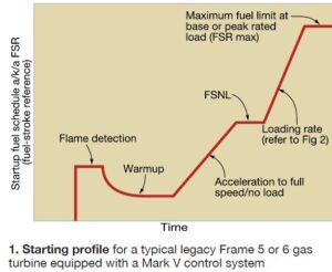
It was developed from a family of algorithms embedded in the Speedtronic™ Mark V control system that program fuel flow during firing, acceleration to full speed/no load (FSNL), and ramp to baseload. GE control-system design addresses the OEM’s concerns about over-firing during startup, as well as about the rate of temperature rise and shaft acceleration.
Note that it is possible to control fuel flow to less than the values illustrated should turbine exhaust temperature or shaft acceleration become excessive during startup.
The loading process from FSNL to baseload or peak power follows the demand for fuel flow according to the three curves shown in Fig 2. Since the unit is synched to the grid, speed (engine and fuel pump) has been eliminated from the algorithm used to draw this portion of the Fig 1 chart.
For simplicity, only three sloped lines are presented in Fig 2. The one to follow depends on compressor inlet temperature (T-amb) and the subsequent level of compressor discharge pressure—called CPD in today’s Speedtronic nomenclature. 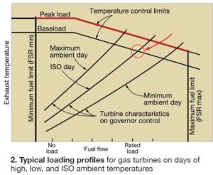
Keeping the turbine under proper control by the Speedtronic system always has been of paramount importance to GE. Setting of fuel limits for fired operation is part of this and dates back to the 1950s when the Young & Franklin fuel regulator was the control device of choice.
Notice that the ambient-temperature curves in Fig 2 extend to different exhaust temperatures. However, all of these end points represent the same turbine firing temperature limit—say 2000F. In some documents, this is called turbine inlet temperature (TIT), calculated at the trailing edge of the first-stage turbine nozzle. The starting points (100% speed) take different amounts of fuel because changes in the density of ambient air affect the CPD value.
The gas-turbine controls are designed to determine, and to limit, turbine firing temperature (Tf ) in the space just upstream of the first-stage buckets (at right in Fig 3); the three-stage turbine section is at the left. Note that (Tf) is not measured but rather a calculated value using thermodynamic equations incorporating CPD, Txa, and constants like the specific-heat values.

Se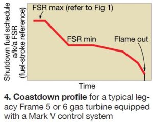 ldom do operators pay attention to the gas turbine during shutdown processes, which can be revealing as to the general health and condition of the machine. The condition of bearings and seals, alignment, and compressor-blade clearances often is unknown. Many plant operators seem only to wait for the turbine to go on ratchet (or turning gear) for cooldown, before departing the site. Scant attention is payed to such things as these:
- Shutdown time. GE does not want to extinguish fuel flow immediately after the main generator breaker (52G) opens during shutdown, but rather reduce fuel flow gradually to avoid quenching the combustion and hot-gas-path components. Operators should pay close attention to the presence of flame as the unit goes from 100% to 80% speed. This takes about two minutes from circuit-breaker opening.
- During spin down, the time to reach rotor rest after flame is extinguished, operators should remain observant. For example, attention should be directed to the time it takes for the rotor to spin freely to rest. If the shaft comes to rest too quickly, it may be indicative of tight or worn bearings, seal rubs, or misalignment of internal components. Also possible on a Frame 5 or 6B: Improper alignment of the load device with respect to the gas turbine.
- Emergency lube-oil pump (88QE) start. Does the pump turn on to assure oil flow all the way down to rotor rest? This is necessary because the main oil pump, gear-driven off the engine rotor, does not deliver sufficient oil at the proper pressure to help cool down the bearings and protect the Babbitt metal against wiping. The emergency lube-oil pump generally has AC and DC motor drivers on the same shaft. When shaft speed drops below about 1000 rpm, the motor-driven pump takes over to provide ample cooling lubricating oil. If AC power is lost, the battery-powered DC motor is activated.
- On Frame 5 and 6B gas turbines, operators should visually confirm that the ratchet cycle has started and that the rotor is actually turning with partial strokes. For Frame 7s, operators should confirm turning-gear start and a slow rolling of the shaft. CCJ